
Hero 40
Joel Cimmino
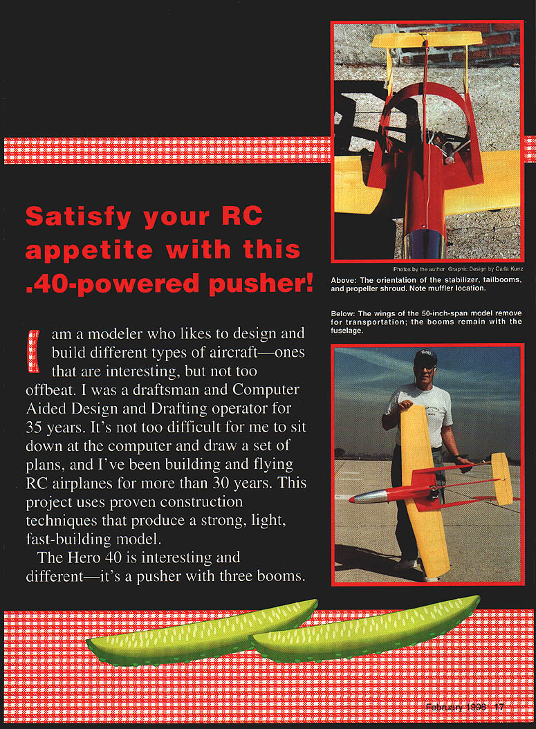
I am a modeler who likes to design and build different types of aircraft—ones that are interesting, but not too offbeat. I was a draftsman and computer-aided design and drafting operator for 35 years. It's not too difficult for me to sit down at the computer and draw a set of plans, and I've been building and flying RC airplanes for more than 30 years. This project uses proven construction techniques that produce a strong, light, fast-building model.
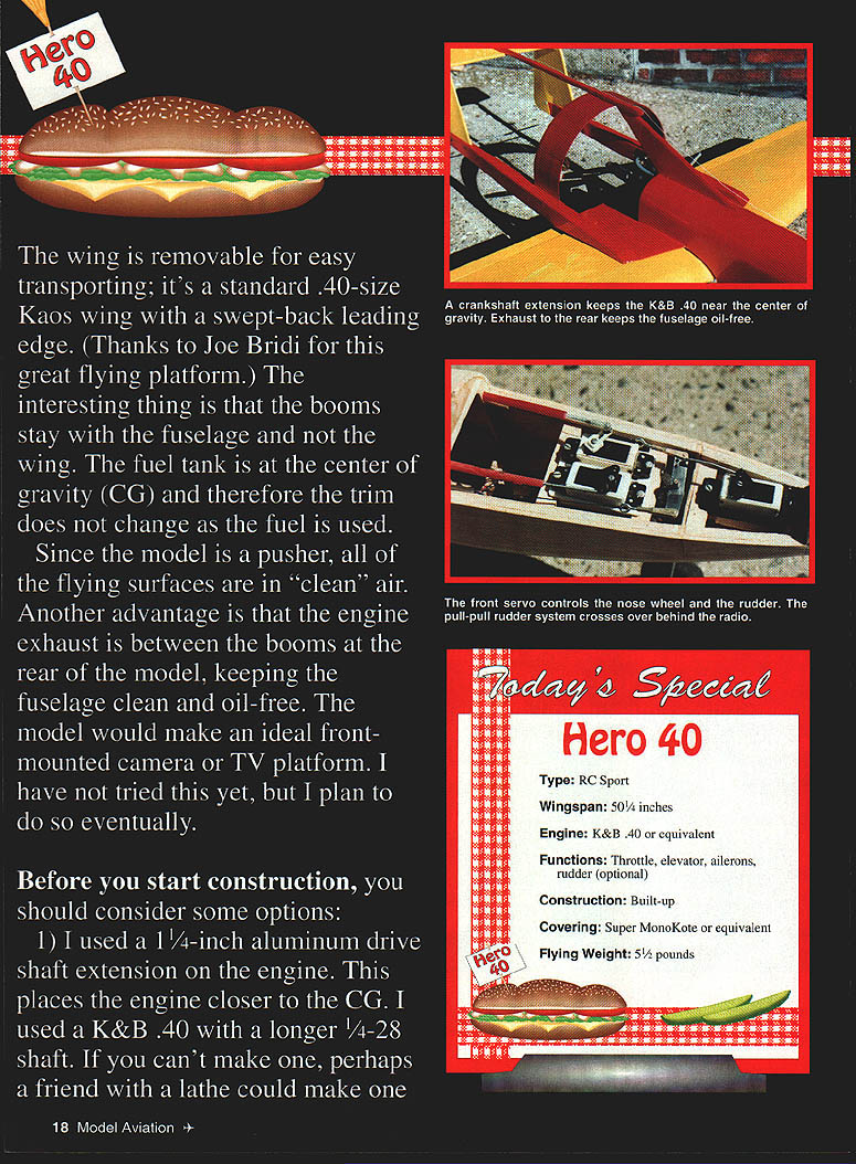
The Hero 40 is interesting and different—it's a pusher with three booms. The wing is removable for easy transporting; it's a standard .40-size Kaos wing with a swept-back leading edge (thanks to Joe Bridi for this great flying platform). The interesting thing is that the booms stay with the fuselage and not the wing. The fuel tank is at the center of gravity (CG) and therefore the trim does not change as the fuel is used. Since the model is a pusher, all of the flying surfaces are in "clean" air. Another advantage is that the engine exhaust is between the booms at the rear of the model, keeping the fuselage clean and oil-free. The model would make an ideal front-mounted camera or TV platform. I have not tried this yet, but I plan to do so eventually.
Before you start construction
Consider these options before beginning:
- I used a 1-1/4-inch aluminum drive-shaft extension on the engine. This places the engine closer to the CG. I used a K&B .40 with a longer 1/4-28 shaft. If you can't make one, perhaps a friend with a lathe could make one; a work-around would use a standard engine — cut 1/2 inch out of the rear center section of the wing for prop clearance.
- If you want rudder control, use a pull-pull system that crosses over the compartment behind the radio receiver to give the correct relation between the rudder and the nose-wheel pickup. Mount the rudder servo well forward so it moves the pickup bar and turns the nose gear at the same time. You can glue the rudders and fins if rudder is not needed; the model will fly without rudder, but I use rudder to save the airplane. I unplug the ailerons just after takeoff.
- If you want to see what effect a prop shroud would have, the model picked up some speed with sufficient power. It would also be possible to use the Hero 40 as an entry-level ducted-fan aircraft.
Construction
Wing
- If you can get a Kaos 40 wing kit you won't have to cut ribs. Make ribs from 3/32-inch sheet if you must cut them. Make photocopies of the ribs and attach the patterns to the sheet with a glue stick. Remove the pattern from the wood right after you cut each rib before the glue has a chance to set.
- Lay down the spars as shown on the plan and glue the ribs in place. I used Titebond II on the entire wing. Glue the top spars in place. Place a tapered jig under the rear ribs. Glue the trailing edge to the rear ribs.
- Make the trailing-edge sheeting from a 25-inch-long piece of 3/32-inch sheet. Save the leftover piece for the center-section sheeting. Glue the pieces in place. Glue the leading-edge ribs.
- Make four pieces of tapered leading-edge sheeting from 1/32-inch sheet; save the leftover wood. Cut a 13 x 1/2-inch triangle from the corner of a 26-inch sheet. Using cyanoacrylate (CyA), glue the top edge to the other end to form the tapered sheeting. The finished sheet will be 4-1/2 inches wide at one end, 26 inches long, and 1/2 inch wide at the other end. Dampen the top sheeting, glue and place.
- Glue vertical webbing between the ribs; this will form the D-tube. Finish the top by adding cap ribs. Sheet the center section and allow to dry.
- Flip the wing over and add a 1/16-inch rib doubler to ribs 2 and 3. Glue the hardwood landing-gear block in place. Cut, fit and glue three filler blocks where the hold-down screws come through the wing. Follow the same steps to complete the bottom wing.
- Make the center-spar brace by adding 1/8-inch plywood on both sides (use 3/32 sheet) and fit it between the top and bottom spars. See the plan for exact size and shape. There is no dihedral; build the wing top-side down. Insert the spar brace between the top and bottom spars and glue both halves of the wing together. Add wingtip blocks. Place the tapered jig under the rear trailing edge and let everything dry.
- Fit the aileron torque rods using 6-inch trailing-edge stock and glue them in place. Make right and left units. Note the aileron hookup is on the bottom side of the wing. Shape, sand and set the wing aside.
Fuselage
- Make formers F1 through F6. Follow the small triangle shown on the plan. Cut the sides of the fuselage from 1/8-inch sheet. Cut 1/4-inch plywood doublers shown on the plan (arrowheads) and glue the doublers to the left and right sides.
- After the sides dry, glue stringers along the top and bottom edges. Carefully mark the location of the formers. Glue formers F1, F2 and F3 in place, being careful to keep the formers square to the sides.
- Attach the Goldberg nose-gear block and former F5. Pull the sides together and glue formers F5 and F6. Add top and bottom stringers. Sheet the top from F1 to F3. Sheet the bottom from F2 to F3. Tack-glue former F4 in place.
- Using strips, plank F4 to F6; start planking the center top. Add planking to the bottom-right section, plank the top-left center section and the left-bottom. Alternate planking the right side and left side and work top and bottom. Planking is one of the harder tasks; to build fast use Titebond between planks and CyA to hold formers — this method requires fewer pins. The area between formers F4 and F6 will be cut off for the access hatch to the radio compartment.
- Plank the bottom from F3 to F6 and set aside to dry. Cut out the access hatch. Glue on the nose block. Make the fin from 1/8-inch Lite Ply. Cut lightening holes and cover the sides with 1/32-inch sheet. Shape and glue the fuselage.
- Make a 1/8-inch Lite Ply platform between the left and right booms using the top view to cut the platform to the size you are going to use with the shaft extension; make the platform 1/2 inch shorter at the trailing edge. Wet the top of the platform, clamp it to the top wing and let it dry; it will have a curve that matches the top wing.
- Glue the platform to the fuselage being very careful to keep the outside edges of the platform parallel to the fuselage sides. Make sure the booms stay parallel to the centerline of the fuselage.
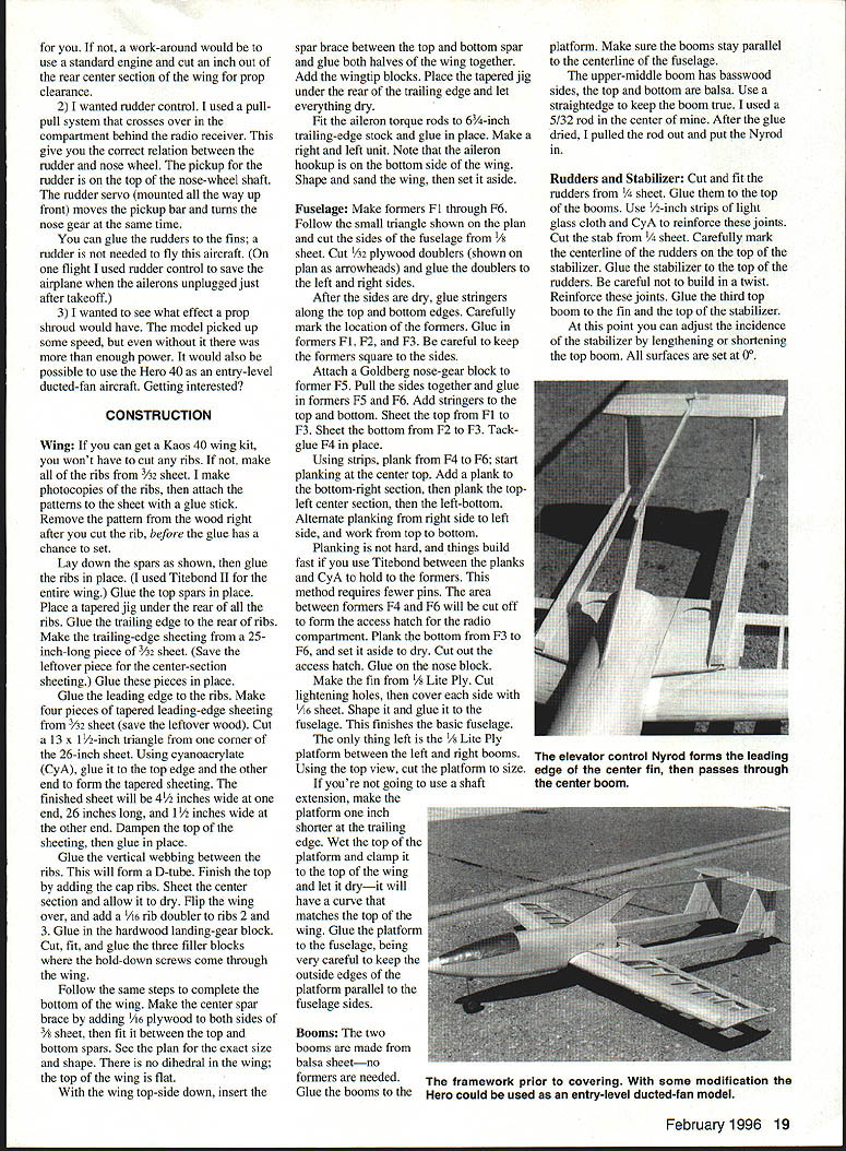
- The upper-middle boom has basswood sides with top and bottom balsa. Use a straightedge to keep the boom true. I used a 5/32-inch rod in the center; after the glue dried pull the rod out and install Nyrod.
Rudders and Stabilizer
- Cut and fit the rudders from 1/4-inch sheet. Glue them to the top of the booms. Use 1/16-inch strips of light glass cloth and CyA to reinforce these joints.
- Cut the stabilizer from 1/4-inch sheet. Carefully mark the centerline of the rudders on the top of the stabilizer. Glue the stabilizer to the top of the rudders. Be careful not to build in a twist. Reinforce these joints.
- Glue the third top boom to the fin and to the top of the stabilizer.
At this point you can adjust the incidence of the stabilizer by lengthening or shortening the top boom. All surfaces are set at 0°.
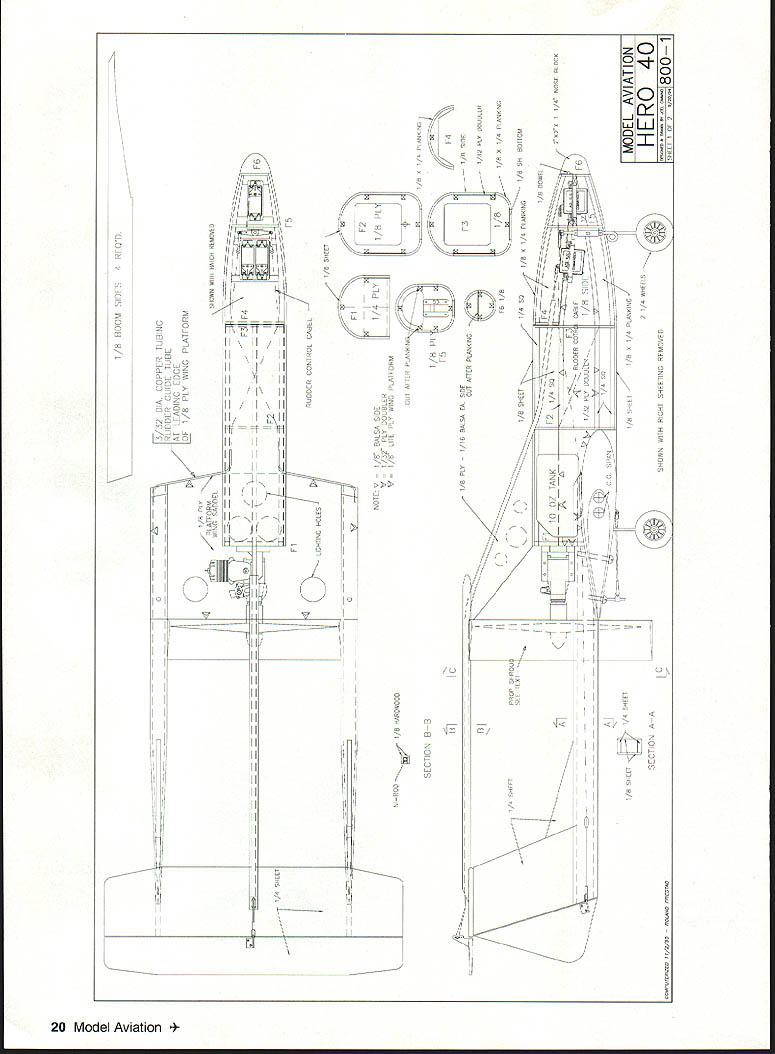
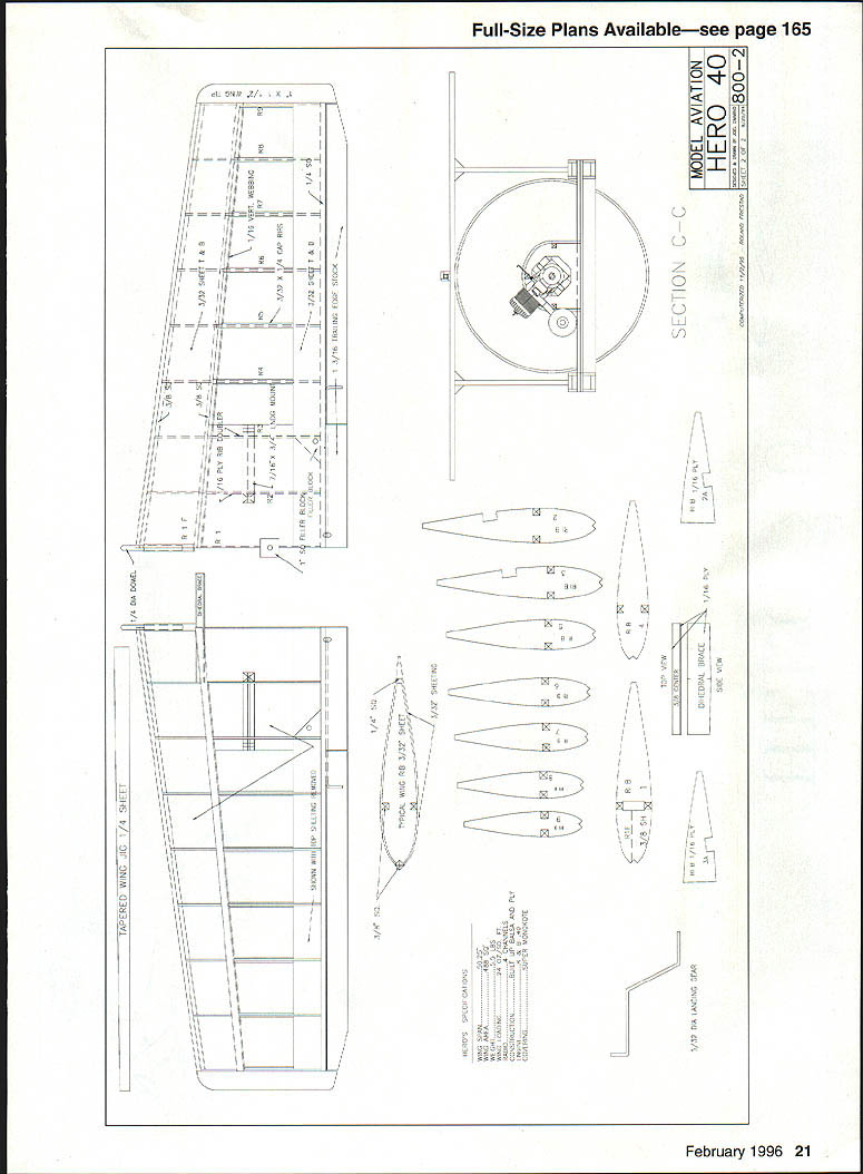
Plans
This scanned page contains full-size plan views, section views, part labels and dimensions for the Hero 40 model. It consists primarily of diagram labels and part callouts rather than continuous article prose.
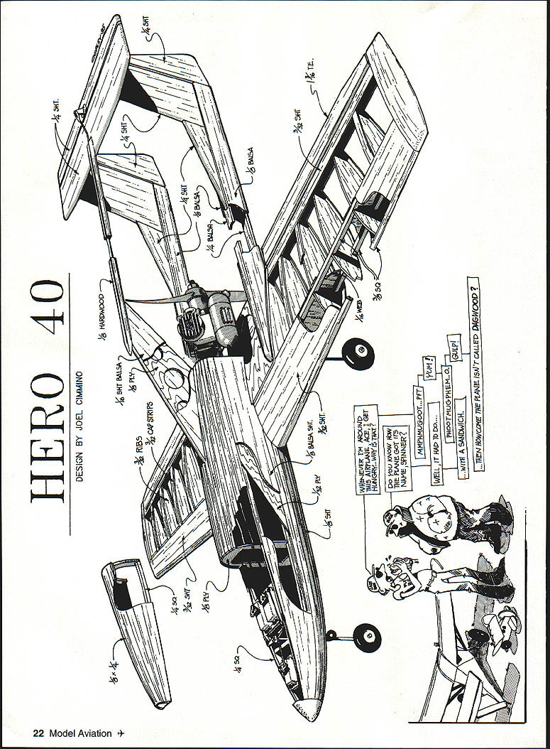
HERO 40 — Design by Joel Cimmino
Prop Shroud
The basic airframe is complete; the prop shroud is not needed to fly this airplane. If you wish to build the shroud, get a five-gallon bucket—the type used for joint compound or laundry detergent. This will be used as the former for the ring. These buckets are 10-1/2 inches in diameter at the bottom—just the right size.
- Cut a 1/8-inch balsa sheet into three-inch strips. Using CyA, glue them side-by-side, forming a cross-grained plank about 33 inches long.
- Place plastic wrap around the bottom of the bucket. Wet one side of the plank, then wrap it around the bottom edge of the bucket. Let it dry. Glue the open ends together to form one big ring around the bottom of the bucket. Epoxy a layer of medium glass cloth around the plank.
- After the epoxy has cured, remove the shroud from the bucket. Now put the prop shroud inside the bucket. Trim and sand the airfoil as shown. You must add a layer of cloth to the inside of the prop shroud. Tack the cloth in place with CyA first. Cut slits that run parallel to the grain, then work the epoxy into the cloth. When the epoxy hardens, sand the shroud completely. The shroud is very strong and light.
I did not use the prop shroud on my first flight. I trimmed the airplane first, then added it on the fifth or sixth flight.
Finish
- After making the ailerons, the elevator, and the rudders, hinge all of the surfaces. Install Nyrods (the type that do not expand or contract with temperature differences) to the elevator and the rudders.
- At this point I add two coats of clear acrylic lacquer to the airframe, sanding between coats. I find that this makes the wood stronger, and the MonoKote seems to stick better.
- My friends tease me because I always make my models' wings yellow and the fuselages red. They say I have 500 yards of each color. They're wrong—I have 1,000 yards of each. Anyway, they're the colors I see best in the air.
- If you are going to use rudder control, install copper tubing (bent in an S shape) to the front of the Lite Ply platform. I originally used 30-pound-test stainless-steel fishing leader for the pull-pull to the rudders. I had problems with radio interference, so I moved the radio antenna from the top boom to the wingtip. I later changed the pull-pull to 30-pound-test monofilament. That cured the interference problem.
- Install the engine and tank. The tank pickup will have to be modified. Bend a U in a length of copper tubing. This goes inside the tank; the pickup will be at the aft end of the tank.
- After all of the radio equipment is installed, check the CG. It should be between the two marks shown on the plan. I found the rear mark (at 30% of the mean chord) to be best.
Flying
The first flight was a knee-knocker. As the model rolled down the runway I held full right rudder to keep it tracking. Picking up speed, I advanced the throttle to full—and the engine coughed. I pulled back on the throttle and the airplane lifted off unexpectedly. I applied power slowly, and proceeded to circle the field. Once around, then I landed.
I had expected the aircraft to pitch down, so I had put up trim in the elevator—it did not need it. Because the mass of the aircraft is concentrated near its center of gravity, the airplane needs little elevator movement. It will respond very quickly to elevator—3/8 inch up and down is all you will need.
The Hero 40 doesn't fly differently than other airplanes, but it definitely looks different in the air. The booms are thin and become virtually invisible.
Landings are a joy. At 5-1/2 pounds the model doesn't want to stop flying. At low throttle, pull back on the stick—when it slows down, the nose comes up, and the model lands on its main gear.
Name and acknowledgments
I should explain how the airplane was named. I had finished building the fuselage one day, and to help the glue dry I took it to the field and left it in the hot car. Around noon I took it out of the car to do some sanding (no mess in the house). Before long I had finished, and I put the fuselage back in the car. Fay, the wife of a fellow flier, asked me if I had finished eating my hero. (Here in New York, a large sandwich on Italian bread is called a "hero.") I explained to her that my new, unnamed airplane was not a sandwich but a triple-boom, swept-wing, 40-size pusher. Fay looked at me and laughed, and asked "Did it have any cheese on it?" And so the name Hero 40.
If you choose to build the Hero 40, let me know how you like it, and what you think we should change.
Thanks to my good friends Norm Franzino and John Barbieri for their suggestions and their editing help. Thanks to my wife for allowing me to spend all that time at the computer and the flying field.
Joel Cimmino 8405 Ave. N Brooklyn, NY 11236
Transcribed from original scans by AI. Minor OCR errors may remain.

