
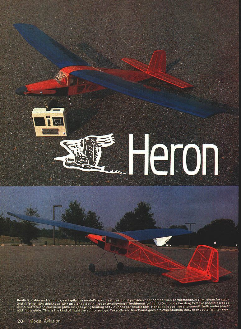
Heron
Realistic cabin and landing gear typify this model's sport appearance, but it delivers near-competition performance. A slim, clean fuselage and an airfoil about 0.100" thick (with an elongated Phillips entry allowing roughly 4° incidence for high L/D) provide low drag for a good climb-out rate and minimum glide sink at a wing loading near 12 oz/ft². Handling is positive and smooth both under power and in the glide. Takeoffs and touch-and-goes are exceptionally easy to execute.
This graceful bird significantly advances performance beyond typical sport models. The Heron blends sport and competition features and is not a "first attempt" aircraft. It is not recommended for anyone who lacks adequate piloting skills and prior electric experience.
Summary of performance highlights
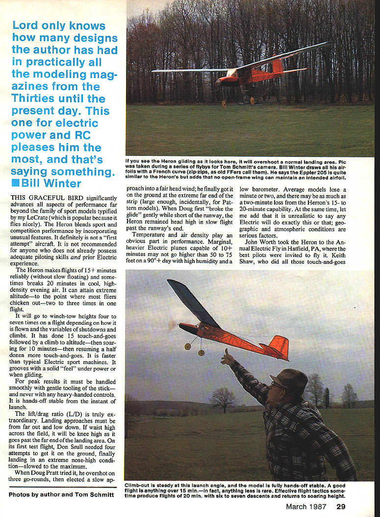
- Reliable flights of 15+ minutes; sometimes exceeds 20 minutes in cool, dense evening air.
- Extreme altitude capability—can climb to uncomfortable heights two to three times in one flight.
- Multiple winch-tow height returns: four to seven times per flight depending on technique.
- Has performed sequences such as 15 touch-and-goes, climb to altitude, ten minutes of soaring, then more touch-and-goes.
- Faster and more solid-feeling under power than typical electric sport planes.
- Very high lift/drag ratio (L/D); landing approaches must be flown far out and low.
Piloting must be smooth—gentle stick movements, no heavy-handed inputs. The model is hands-off stable immediately after launch.
Performance and field reports
Temperature and air density significantly affect performance. On hot, humid, low-barometer days, marginal electric planes that normally do 10+ minutes may only climb 50–75 ft; similarly, the Heron may lose a minute or two of duration compared with cool, dense-air performance. Geographic and atmospheric conditions are serious factors.
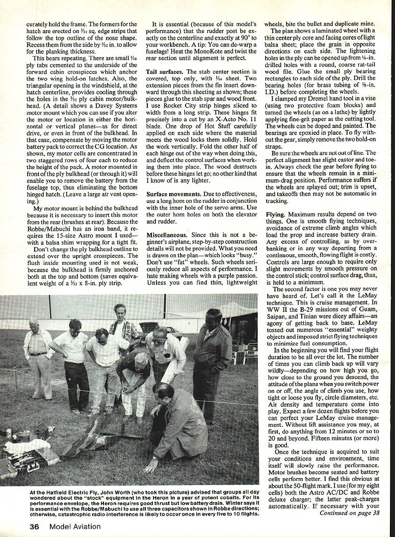
At the Annual Electric Fly in Hatfield, PA, the Heron was flown by many of the best pilots:
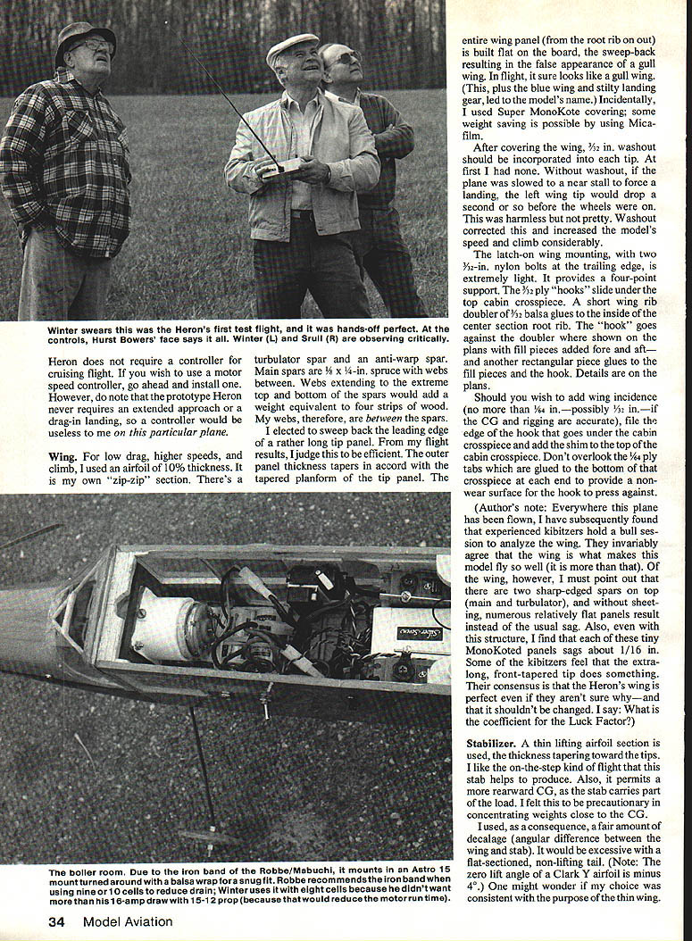
- John Worth demonstrated it; Keith Shaw, Bill Winter, Bob Kopski, Woody Blanchard, Heinz Koerner, Hurst Bowers, and Tom Schmitt all flew it or commented on it.
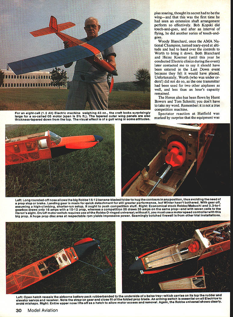
- Spectators were surprised by the equipment, especially the long rounded-off nose that allows a big Robbe 15x12 banana-bladed folding prop to hug the fuselage contours, avoiding a prop stop or brake.
- Woody Blanchard (AMA National Champion) became emotional at altitude; several pilots felt the Heron would have placed in the Last Down contest.
Propulsion and motor installation
The author’s final propulsion system:
- Motor: Robbe/Mabuchi unit (identified with the Robbe iron band in the installation).
- Gearbox: Robbe geared unit (author uses 3.1:1 in his installation).
- Prop: Robbe 15x12 banana-bladed folder (about 14.9" dia).
- Batteries: eight 1.2 Ah cells (two staggered rows of four).
Key points:
- With the Robbe gearbox and the big folder, ground draw is about 16 A; in flight it may unload to ~12 A. This is roughly 60% of the drain of a comparable competition .05 running the same prop on seven cells.
- Robbe supplies a version of the motor with an iron band; the author believes the band helps limit drain/overheating when using higher cell counts. Robbe recommends removing the band when using eight cells or fewer, but the author prefers to keep the band on with eight cells for his installation.
- Motor location in the cabin (behind the bulkhead) concentrates mass near the center of gravity (CG), improving handling by minimizing long moment arms.
- The on/off motor switch requires a Robbe universal with sturdy O-rings to absorb start-up shock when using a large folder. A motor-speed controller is recommended; a simple on/off combined with a large prop and low gear ratio can damage a universal or belt drive.
- The huge prop disc at moderate RPM yields impressive thrust without excessive current draw in this installation.
Notes on gear ratios and currents:
- Gear ratios significantly affect current draw. Different ratios and props will produce widely different amp readings; example figures in trials showed large variance. Expect individual motors to vary 10–15% between production runs.
- The Robbe/Mabuchi motor used by the author cost about $36 when purchased.
Wing
Airfoil and structure
- Airfoil: about 10% thickness, the author's own "zip-zip" section (similar in concept to the Eppler 205 with a long Phillips entry).
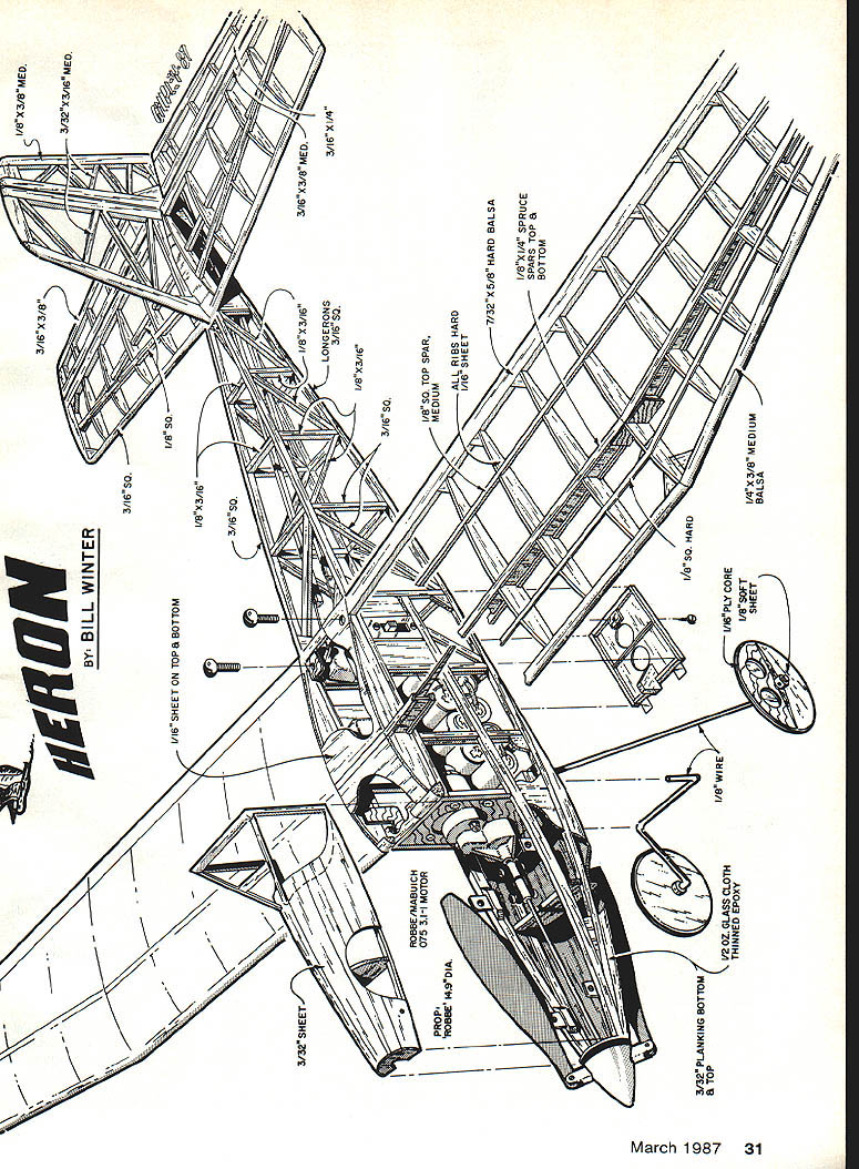
- Construction: turbulator spar and anti-warp spar; main spars are 1/4" x 1/4" spruce with webs between. Webs are placed between the spars to save weight.
- Panels: the wing is built flat on the board; sweepback of the leading edge on the tip panel produces a gull-wing appearance in flight and is judged efficient by flight results.
- Covering: Super MonoKote used; Micafilm would save some weight.
- After covering, add 3/32" washout at each tip. Initial tests without washout showed a slight left tip drop near stall; washout corrected this and improved speed and climb.
Mounting and incidence
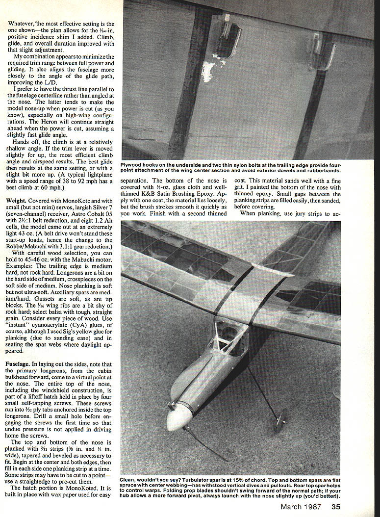
- Latch-on wing mounting: two 3/32" nylon bolts at the trailing edge and 3/32" ply hooks that slide under the top cabin crosspiece provide a light, four-point support. A short rib doubler on the center section root rib reinforces the hook area.
- To add wing incidence (no more than 1/2"—preferably 3/8" if CG and rigging are accurate), file the edge of the hook and add a horn to the top cabin crosspiece. Glue 1/64" ply tabs to the bottom of the crosspiece to provide a non-wear surface.
Author’s note: Experienced observers at flying events attribute much of the Heron's success to the wing. The thin-panel structure causes some slight sag (about 1/16") under MonoKote; the long tapered tip may contribute to the excellent performance.
Stabilizer
- Stab uses a thin lifting-sectional airfoil with taper toward the tips.
- The lifting stab allows a more rearward CG and carries part of the load—useful for concentrating weights near the CG.
- Author employed noticeable decalage (angle difference between wing and stab); this would be excessive with a flat-section tail.
- The zero-lift angle of a Clark Y is −4°, for reference.
Weight
With MonoKote covering, mid-size servos, a seven-channel receiver, an Astro Cobalt 05 with 2½:1 belt reduction (earlier trials), and eight 1.2 Ah cells, the model weighed about 43 oz. The final installation uses the Robbe/Mabuchi with 3.1:1 reduction and careful wood selection to keep gross weight around 43–46 oz.
Wood selection tips:
- Trailing edge: medium-hard balsa.
- Longerons: slightly harder than medium.
- Crosspieces, gussets, tip blocks: on the softer side.
- 1/16" wing ribs: choose balsa with tough, straight grain.
- Use instant cyanoacrylate (CyA) glue generally; Sig yellow glue is good for planking where sanding ease is needed.
Fuselage
- Layout: primary longerons from the cabin bulkhead forward come to a virtual point at the nose.
- Hatch: the entire top of the nose and windshield area form a lift-off hatch held by four small self-tapping screws into 1/8" ply tabs. Drill pilot holes before first engagement to avoid splitting.
- Nose planking: 3/32" strips (3/8" and 1/8" wide) tapered and beveled as needed. Build from center outward, cutting strips to fit as required.
- Hatch is built in place over wax paper for easy separation and then MonoKoted.
- Bottom of nose: 4-oz glass cloth with thinned epoxy (two coats recommended); sands well and gives a durable finish. Paint the bottom with thinned epoxy.
- Use jury strips to hold the frame accurately when planking. Build hatch formers on 3/32" square strips recessed 3/32" for planking thickness.
- Cooling: a triangular opening in the windshield provides cooling through holes in the 3/32" ply cabin motor/bulkhead. Good exit venting is recommended.
- Motor pack arrangement: author concentrates cells in two staggered rows to lower pack height. If you move the motor forward, compensate battery placement to maintain CG.
Motor mount: the Robbe/Mabuchi used requires the 15-size Astro mount with a balsa shim for a tight fit. Do not extend the ply bulkhead over the upright crosspieces—flush inside mounting is strong and saves weight.
Alignment tip: the rudder post must be exactly on the centerline and 90° to the workbench. You can de-warp a fuselage by heating the MonoKote and twisting the rear section to correct alignment.
Tail surfaces and control linkages
- Stab center glued with top 1/16" sheet; two fin extension pieces insert downward through the sheeting and glue to the stab spar.
- Hinges: Rocket City strip hinges sliced to width; fit into cuts made with an X‑Acto No. 11. One drop of Hot Stuff CA on each side where hinge material meets wood secures them. These hinges are extremely light and strong.
- Surface movements: use a long rudder horn combined with inner servo-arm holes; use outer horn holes on the elevator and rudder for leverage.
Wheels and landing gear
- Avoid fat wheels; they reduce performance. The plan shows a laminated wheel: thin center ply core with facing light balsa sheet, grains opposite each side. Lightening holes can be formed from drilled 1/4" holes and finished with a coarse round file.
- Glue small ply bearing rectangles to each side of the ply and drill bearing holes for 1/8" I.D. brass tubing before final assembly.
- The author turned wheels on a clamped Dremel, using fine-grit paper as the cutting tool. Bearings are epoxied in place.
- Gear alignment: slight caster and toe-in are ideal. Always check gear alignment before flight; splayed wheels hurt performance and tracking.
- Gear detachment: landing gear is made for quick removal to improve climb and reduce takeoff run.
Construction notes and cautions
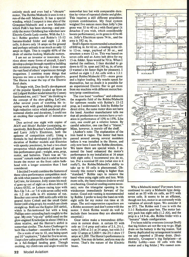
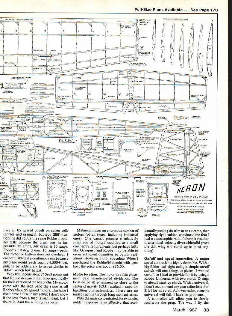
- The plan provides construction details; this is not a beginner's airplane. The plan appears busy but contains needed details.
- Use 1/64" ply tabs under the forward cabin crosspiece to anchor wing hold-on latches.
- Use Rocket City or similar light hinges, CyA glues for most assembly (yellow glue for planking where sanding is heavy).
- For the hatch screws, use small self-tapping screws into ply tabs—not into balsa alone.
- Be meticulous about wood selection and trimming to meet weight and balance targets.
Flying technique
Maximum results depend on two things:
- Smooth flying technique:
- Avoid extreme climb angles that load the prop and increase battery drain.
- Use slight, smooth control movements; large inputs waste energy and upset trim.
- The Heron is capable of hands-off stable climb-outs and long glides, so maintain flowing flight.
- "LeMay" cruise management:
- Named after wartime B-29 tactics to minimize fuel use—applies here to manage battery and motor temperature and extend duration.
- Flight duration initially varies; learn how high to climb, how close to descend, attitude when switching power, climb angle, circle diameter, etc.
- Expect several dozen flights to perfect cruise management. Flight times initially may range from about 12 to 20+ minutes; 15 minutes is a reasonable starting expectation.
Practical in-flight tips:
- As climb develops, wait until good airspeed then increase slight up-trim to achieve the desired climb angle while initiating a wide, shallow-banked turn that can be maintained hands-off.
- If smoke or sluggish climb appears on final climbs, shut down to preserve battery capacity for go-arounds.
- The Heron is forgiving in go-arounds and can be maneuvered quickly for aborted approaches.
Preflight, batteries and chargers
- Display name and address on the model.
- Ground check the radio and range before every flying session.
- Use fresh packs; do not use old packs showing more than ~10% capacity loss.
- The author uses eight 1.2 Ah cells for the motor pack and finds that motor brushes and battery performance often improve after many flights (around the 50-flight mark).
- Charging:
- The author uses both an Astro AC/DC and a Robbe deluxe peak charger (the latter peak-charges automatically).
- Recommended charge per cell while charging ranges roughly 1.4–1.6 V; 1.5 V under charge is a practical target unless you can monitor peak-charging accurately with a digital voltmeter.
- Small flight packs (e.g., 250 mAh) can perform surprisingly well for radio/receiver/transmitter use, but monitor capacity closely. Replace packs showing significant capacity loss.
Experimentation and alternatives
- Experiment with different motors, gearboxes, cell counts, and cell capacities (e.g., 800 mAh cells). Duration, climb and glide will vary with each combination.
- A geared Astro Cobalt .05 with seven 800 mAh cells and the landing gear removed can bring the Heron closer to full competition performance.
- The model’s design is flexible; experienced electric fliers can optimize motor/battery/prop combinations to suit their goals.
Final note
The Heron is a high-performance electric sailplane that sits near the top of the electric food chain in the author’s view. It combines a low-drag airframe, thoughtful mass distribution, and a powerful, efficient prop/gear/battery installation. The author prefers his Heron exactly as built, but encourages careful, experienced builders to experiment to achieve their own optimum setup.
Transcribed from original scans by AI. Minor OCR errors may remain.

