
Hi-Tech 2001
Thomas J. Hunt
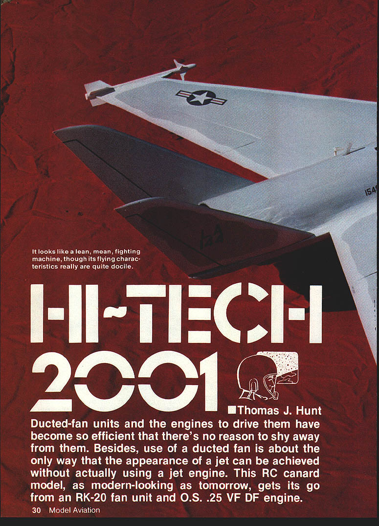
Ducted-fan units and the engines to drive them have become so efficient that there's no reason to shy away from them. Besides, use of a ducted fan is about the only way that the appearance of a jet can be achieved without actually using a jet engine. This RC canard model, as modern-looking as tomorrow, gets its go from an RK-20 fan unit and an O.S. .25 VF DF engine.
The first of two prototype aircraft (Hi‑Tech 2000) reached the 350-ft. mark at a 400-ft. paved runway and still didn't seem interested in flying. I pulled the stick back hard just to see what would happen, and the aircraft jumped 18 in. off the ground and then promptly settled back 9 in. When I relaxed the "up" command a bit, the aircraft gradually climbed into the sky. Fearing that making a turn too soon after lift-off would stall the aircraft, I waited until it had nearly left the perimeter of the field before I made a gentle right-hand turn.
The aircraft responded well to the aileron command, but it refused to climb any higher. Was it underpowered or overweight, or was the engine just not performing well? I made a few turns at the downwind end of the runway and decided that Hi‑Tech 2000 was just too heavy. The nose-high attitude required to lift the weight also produced so much drag that the plane couldn't accelerate to a comfortable cruising speed.
I set up for a normal approach to the same runway it had departed from. By then the wind was approximately 45° to the runway. I kept the nose and power high, stretched the approach with what additional power I had left, and managed a surprisingly well-controlled landing on the runway. All this time, George Myers was capturing the aero-ballet on 8mm film so I could laugh later at what I had done.
From the flight characteristics, I concluded that the center of gravity (CG) on Hi‑Tech 2000 was slightly too far forward, so I decided to fly my Hi‑Tech 2001 only after moving the CG aft about 1/2 in. The propulsion unit was removed from Hi‑Tech 2000 and installed in Hi‑Tech 2001 in about five minutes. Hi‑Tech 2001 is slightly smaller and a pound lighter than the 2000. Meanwhile, a change of wind forced a change of runway (the field I fly at has two paved runways — approx. 50 ft. wide and 400 ft. long — running east/west and north/south).
The engine was started, and Hi‑Tech 2001 was placed exactly at the beginning of the N/S runway. The throttle was slowly advanced. This time, the acceleration was brisk. I decided to hold the aircraft on the runway with a little down stick, to gain as much speed as possible before rotating it. At about the halfway point, I pulled what I thought of as only a little "up." To my surprise the aircraft leaped off the ground in a very nose-high attitude.
Questions raced through my mind in those first milliseconds. Did I move the CG back too far, making it unstable? Was the machine severely out of trim? Were the control throws just much too large, thereby making the plane over-sensitive?
After flying through a few sine waves, I calmed down myself and the plane and proceeded to climb to altitude. I trimmed the aircraft and decided that it was a little too sensitive in pitch; I had put excessive control throws on the canard and its coupled vane. I convinced myself to limit my control inputs.
Later, I looped, rolled, and flew Hi‑Tech 2001 inverted, all during that first flight. What a difference a pound makes! I then felt comfortable with the aircraft, so I tried a few landing approaches. The aircraft shows a tendency to "float" on final with the nose and power high, but was rock-steady in roll and yaw, and I could easily control the descent with power. The touchdown was accomplished at a very trainer-like pace. Hi‑Tech 2000 and 2001 are both definitely easy to land.
The control vane in Hi‑Tech 2001's fan duct produced instantaneous responses to my commands at very slow flying speeds (during some aborted landings), reaffirming my decision to use the vane to assist the canard instead of depending on elevons as in Hi‑Tech 2000. Inverted flight was very stable in spite of the fact that the wing and canard have a lot of twist (an upright design necessity for slow flight). After the vane control throw was reduced, the aircraft became less sensitive. Subsequent flights showed Hi‑Tech 2001 to be a pleasant, predictable airplane to fly.
I believe that, because of Hi‑Tech 2001's excellent low-speed flight qualities and predictable aerobatic performance, anyone who can handle an advanced aileron trainer can also fly this aircraft.
You just have to be prepared for the different takeoff characteristics of a ducted-fan model. Ducted-fan models accelerate much slower than their prop-driven counterparts of similar weight. This extends the runway length required to get the craft airborne. Also, ducted-fan models do not have the advantage of a prop blast on the elevator and rudder to make them effective at slow flying speeds. This also increases takeoff and landing distances in conventional ducted-fan models, as you must wait longer before the control surfaces become effective. The addition of the control vane in the wake of the fan exhaust (in Hi‑Tech 2001) alleviates the latter problem. However, only a lightly-built aircraft will get into the air in a hurry and provide snappy performance. Hi‑Tech 2001 fills the bill.
Canard philosophy
These aircraft are ancient — the Wright brothers flew one — but they have not been widely accepted. However, due to the efforts of Burt Rutan and a few other home-builders, the canard aircraft is now becoming more popular and better understood. Subsonic canard aircraft can provide improved fuel efficiency, improved safety (better stall characteristics), and allow more usable space in the fuselage.
Hi‑Tech story
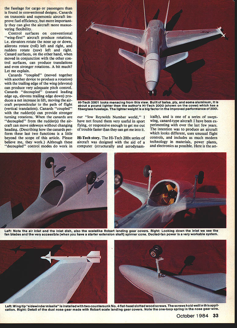
The Hi‑Tech 200x series of aircraft was designed with the aid of a computer (structurally and aerodynamically), and is one of a series of swept-wing, canard-type aircraft I have been experimenting with over the last few years. The intention was to produce an aircraft which looks different, uses unusual flight controls, and includes as much modern technology in materials, power plants, and electronics as possible. Here is the setup.
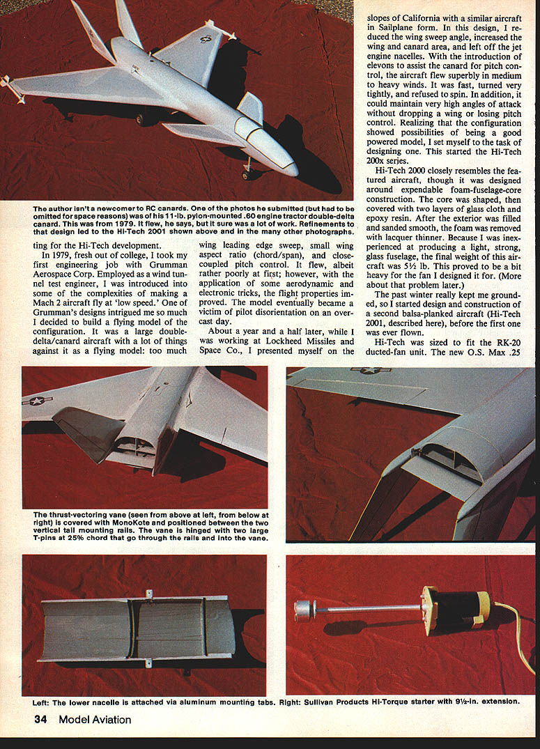
Testing for the Hi‑Tech development. In 1979, fresh out of college, I took my first engineering job with Grumman Aerospace Corp. Employed as a wind-tunnel test engineer, I was introduced to some of the complexities of making a Mach 2 aircraft fly at low speed. One of Grumman's designs intrigued me so much I decided to build a flying model of the configuration. It was a large double-delta/canard aircraft with a lot of things against it as a flying model: too much wing leading-edge sweep, small wing aspect ratio (chord/span), and close-coupled pitch control. It flew, albeit rather poorly at first; however, with the application of some aerodynamic and electronic tricks, the flight properties improved. The model eventually became a victim of pilot disorientation on an overcast day.
About a year and a half later, while I was working at Lockheed Missiles and Space Co., I returned to the slopes of California with a similar aircraft in sailplane form. In this design, I reduced the wing sweep angle, increased the wing and canard area, and left off the jet engine nacelles. With the introduction of elevons to assist the canard for pitch control, the aircraft flew superbly in medium to heavy winds. It was fast, turned very tightly, and refused to spin. In addition, it could maintain very high angles of attack without dropping a wing or losing pitch control. Realizing that the configuration showed possibilities of being a good powered model, I set myself to the task of designing one. This started the Hi‑Tech 200x series.
Hi‑Tech 2000 closely resembles the featured aircraft, though it was designed around expendable foam-fuselage-core construction. The core was then shaped, covered with two layers of glass cloth and epoxy resin. After the exterior was filled and sanded smooth, the foam was removed with lacquer thinner. Because I was inexperienced at producing a light, strong glass fuselage, the final weight of this aircraft was 5½ lb. This proved to be a bit heavy for the fan I designed it for.
The past winter really kept me grounded, so I started design and construction of a second balsa-planked aircraft (Hi‑Tech 2001, described here), before the first one was ever flown.
Hi‑Tech was sized to fit the RK-20 ducted-fan unit. The new O.S. Max .25 VF DF engine was chosen for power because it was, at the time, a new engine designed specifically for ducted fans. A MACS Products tuned pipe was also used for extra power.
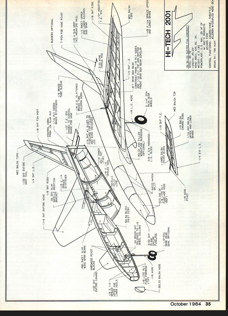
Hi‑Tech 2001 (specifications)
An RK-20 ducted-fan aircraft
- Scale: 1/6
- Wingspan: 48-1/2 in.
- Length: 57-1/2 in.
- Weight: 4-1/2 lb.
- Power plant: O.S. Max .25 VF DF
- Fuel: 6 oz.
- Controls: Throttle, elevons, rudder
You will notice dihedral in the canards, anhedral in the wing, and outwardly-canted vertical tails. The canard dihedral is an attempt to keep the flow of air behind the canard from upsetting the inboard section of the wing. The anhedral in the wing is used to reduce some of the roll stability achieved from the high leading-edge sweep angle. The outward cant of the vertical tails is purely aesthetic on this model, although it does help yaw control and reduce drag on transonic aircraft.
Hi‑Tech 2000 utilized elevons to help the canard in pitch control. Hi‑Tech 2001 utilizes a movable vane in the wake of the fan exhaust to assist the canard, instead of elevons. The purpose was to enable pitch control well below the airspeed at which the canard and wing elevons were no longer effective.
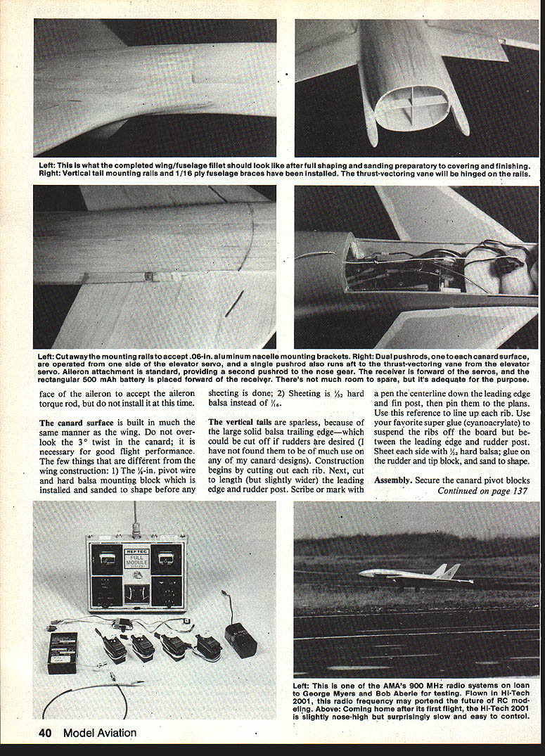
The radio with which I chose to control the prototype is the new Airtronics Championship Series, seven channels. This radio, if you are not familiar with it, has many programmable features (servo reversing, expo/linear, rudder/aileron coupling, end point adjustment, dual rates, and a plug-in V-tail mixing board). I also had the opportunity to install and fly the aircraft with one of AMA's experimental 926 MHz radios that was on loan to George Myers and Bob Aberle for evaluation.
Construction
Although the configuration of the aircraft is very different from the usual RC model, its construction is conventional. You should have very little difficulty in duplicating my airplane. Construction poses no real problem for even a novice builder. This could be your first fan aircraft, because Hi‑Tech 2001 was my first one (except for the first prototype Hi‑Tech 2000, which was built concurrently). Build yourself one, and go dog-fight your flying buddies with an airplane that looks 10 to 15 years ahead of its time.
Fuselage
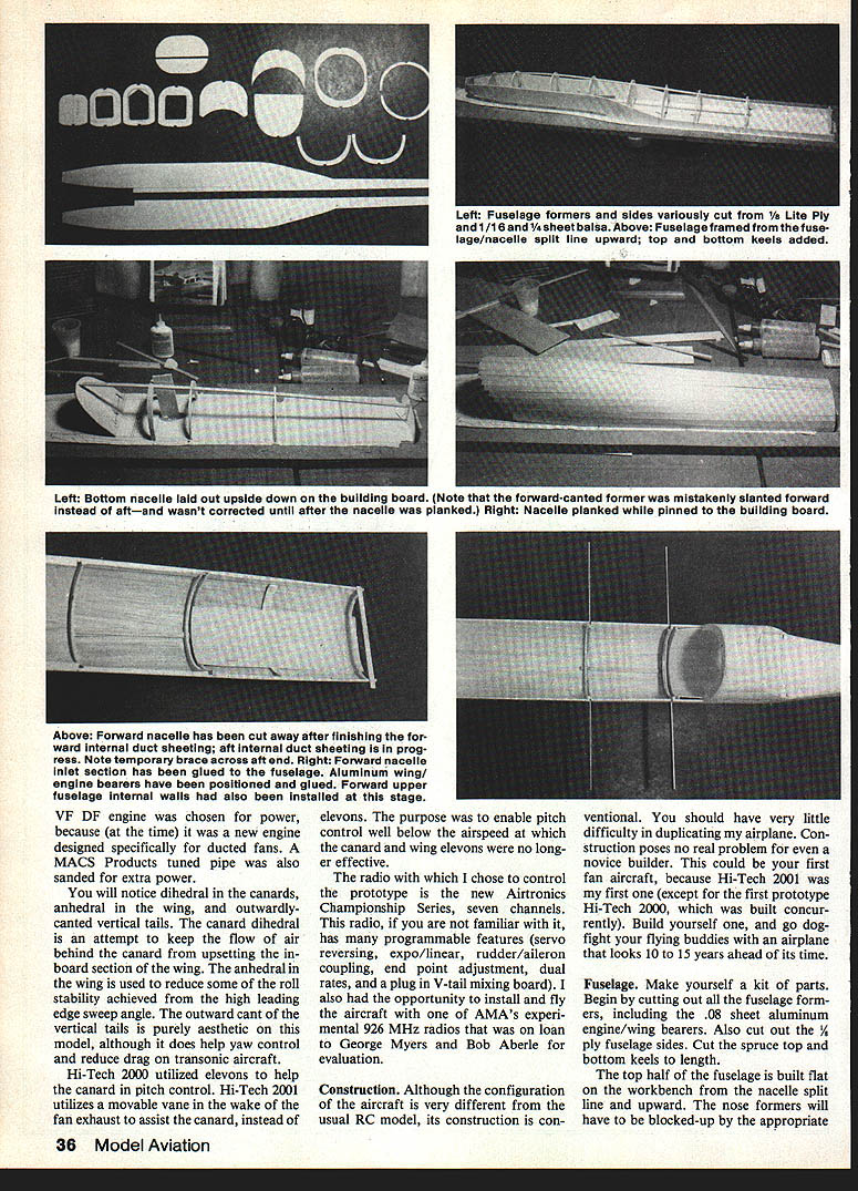
Make yourself a kit of parts. Begin by cutting out all of the fuselage formers, including the .08 sheet nacelle engine/wing bearers. Also cut out the 1/8 ply fuselage sides. Cut the nacelle top and bottom keels to length.
The top half of the fuselage is built flat on the workbench from the nacelle split line and upward. The nose formers will have to be blocked up by the appropriate thickness of shims. Plank the top half of the fuselage with 1/8-in. sheet balsa. The nacelle is built the same way, but pin the nacelle upside down on the building board so the forward cant former will be held in the correct position. Glue the nacelle to the fuselage and install the top and bottom keels.
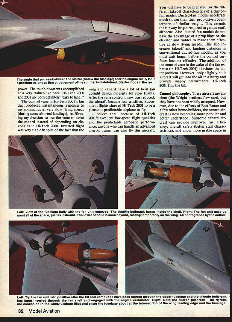
Cut openings in the fuselage sides for the carburetor and throttle bellcrank as required. The throttle bellcrank hangs inside the shell; the right fan unit uses up space and should be lowered in the nacelle. Insert the throttle bellcrank through the fan shell so it will engage the engine carburetor.
Note that aileron pushrods are concealed where the wing/fuselage fillet enters the fuselage at about the wing leading-edge intersection.
The forward nacelle upper internal duct sheeting and forward internal duct sheeting are installed as the nacelle is planked. Temporary braces across the nacelle inlet section are used while the inlet section is being glued to the fuselage. Aluminum wing/engine bearers have been positioned and glued. Forward upper fuselage internal walls are also installed at this stage.
Remove any forward nacelle internal braces and finish fairing the firewall, then install the fan and spinner, maintaining long firm engagement of the spinner with the fuselage.
Stand the remaining formers upright directly on the building board. Be sure not to glue F3a to F3 or F5a to F5 — these must separate later to form the radio hatch. You may, at this time, crack F4 at the top of the ply sidewall to facilitate the radio hatch removal after the fuselage has been planked. Do not install the .08 aluminum formers yet. Plank the entire upper fuselage with 1/32-in. strips of 1/4 to 1/8-in. width. Build the lower nacelle upside down in much the same manner as the upper fuselage.
After the outside of the lower nacelle has been planked, the internal duct lines can be formed out of 1/16-in. sheet, with the fan unit temporarily in place. I suggest you lay the internal sheet balsa in left and right halves, or possibly in thirds, depending upon the softness of your balsa. Install and roughly shape the balsa block for the fuselage inlet dish. Then form the upper inlet and exhaust walls in the same manner as the lower nacelle.
At this point, cut the lower nacelle into the three pieces as shown on the plans. Dress the mating edges with extra sheet balsa and/or filler material. Glue the forward and aft parts of the lower nacelle to the upper fuselage. Sand the air inlet lip to approximately a 1/8-in. radius. Install the 3-ply cross braces in the rear to add strength to the rear fuselage.
Cut a notch in the upper spruce keel to accept the two aluminum formers. You will also need to cut into the ply fuselage sides to fit these formers. Be sure the spacing of these two formers complies with the inside dimension between the two external aluminum wing/engine bearers. Install flanges on your fan unit.
These formers take all the wing load and help secure the fan unit, so be sure they are properly aligned and fastened to the fuselage. I glued mine first with a mixture of baking soda and Hot Stuff and then backed that up with some RTV (silicone sealer).
Glue on the nose block, sand it and the entire fuselage smooth, then cut off the radio hatch. Dress the edges, add the 1/16-in. ply alignment tabs, and refit it to the fuselage. Re-sand and fit on the fuselage each time you add balsa or filler. Install the 1/8-in. x 1/32-in. underfin mounting rails against the side of the fuselage.
Cut two rib fillers from 1/8-in. sheet balsa identical to W1, and glue them to the fuselage sides; make sure that the proper incidence, left to right, is achieved.
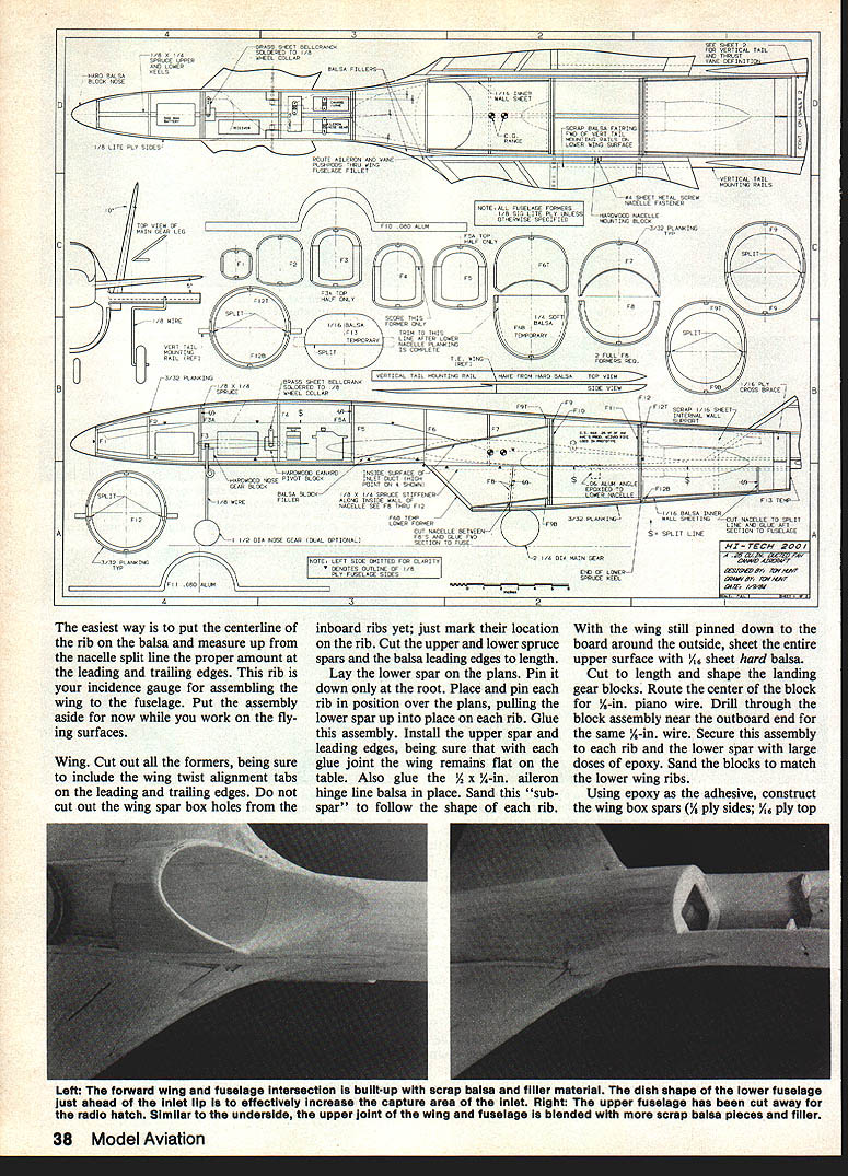
The easiest way is to put the centerline of the rib on the balsa and measure up from the nacelle split line the proper amount at the leading and trailing edges. This rib is your incidence gauge for assembling the wing to the fuselage. Put the assembly aside for now while you work on the flying surfaces.
Wing
Cut out all the formers, being sure to include the wing twist alignment tabs on the leading and trailing edges. Do not cut out the wing spar box holes from the inboard ribs yet; just mark their location on the rib. Cut the upper and lower spruce spars and the balsa leading edges to length.
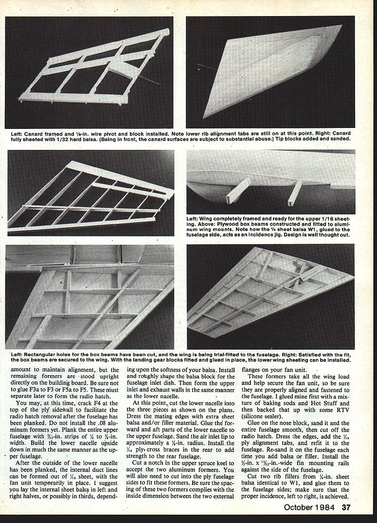
Lay the lower spar on the plans. Pin it down only at the root. Place and pin each rib in position over the plans, pulling the lower spar up into place on each rib. Glue this assembly. Install the upper spar and leading edges, being sure that with each glue joint the wing remains flat on the table. Also glue the 1/2 x 1/4-in. aileron hinge line balsa in place. Sand this "sub-spar" to follow the shape of each rib.
With the wing still pinned down to the board around the outside, sheet the entire upper surface with 1/16-in. sheet hard balsa. Cut to length and shape the landing gear blocks. Route the center of the block for 1/8-in. piano wire. Drill through the block assembly near the outboard end for the same 1/8-in. wire. Secure this assembly to each rib and the lower spar with large doses of epoxy. Sand the blocks to match the lower wing ribs.
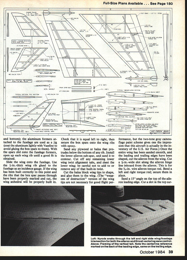
Using epoxy as the adhesive, construct the wing box spars (1/8-in. ply sides; 1/8-in. ply top and bottom). The aluminum formers attached to the fuselage are used as a jig (coat the aluminum lightly with Vaseline to avoid gluing the box spars to them). With the spars slid onto the fuselage formers, open up each wing rib until a good fit is obtained.
Slide the wing onto the fuselage. Use the 1/8-in.-thick wing rib glued to the fuselage as an incidence gauge. If the wing has been built correctly to this point and the ribs that the box spar passes through have been properly marked and cut, the wing anhedral will be properly built in.
Check that it is equal left to right, then secure the box spars onto the wing ribs with epoxy.
Sand any plywood or balsa that protrudes below the bottom of any rib. Install the lower aileron sub-spar, and sand it to contour. Cut off any remaining lower wing twist alignment tabs, and sheet the lower wing; be careful not to add to or remove any of that built-in twist.
Cut the balsa block wing tips to shape, and glue them to the wing. (The "weapons of destruction" version of the wing tips are not necessary for good flight performance, but the two-tone gray camouflage paint scheme gives one the impression that this aircraft is actually in the inventory of the U.S. Air Force.) Once the entire wing has been sanded smooth, and the leading and trailing edges have been shaped, cut the aileron from the wing. Cut a 1/8-in.-wide slot along the aileron hinge line inboard from the aileron. This is for the 1/8-in. wire aileron torque rod. Bend a left and right torque rod; secure them in place.
Sand a 15° angle on the top of the aileron leading edge. Cut a slot in the top surface of the aileron for the torque rod. Sand the face of the aileron to accept the aileron torque rod, but do not install it at this time.
The canard surface is built in much the same manner as the wing. Do not overlap the 3° twist in the canard; it is necessary for good flight performance. The few things that are different from the wing construction are: 1) the 1/4-in. pivot wire and hard balsa mounting block which is installed and sanded to shape before any sheeting is done; and 2) sheeting is 1/32-in. hard balsa instead of 1/16-in.
The vertical tails are sparless, because of the large solid balsa trailing edge — which could be cut off if rudders are desired (I have not found them to be of much use on any of my canard designs). Construction begins by cutting out each rib. Next, cut to length (but slightly wider) the leading edge and fin post. Scribe or mark with a pen the centerline down the leading edge and fin post. Use this reference to line up each rib. Use your favorite super glue (cyanoacrylate) to suspend the ribs off the board but between the leading edge and fin post. Sheet each side with 1/32-in. hard balsa; glue on the rudder and tip block, and sand to shape.
Assembly
Secure the canard pivot blocks in the fuselage with epoxy. Drill through the fuselage and block with a 5/32 drill at a 5° angle to the horizontal. Insert a 1/8-in. I.D. brass tube in the drilled hole; this is the canard pivot bearing. Glue in place the hardwood nose gear block with epoxy. Drill a 1/2-in. hole for a 1/8-in. I.D. brass tube; this is the nose gear pivot bearing. If you are using an offset nose gear, you may wish to drill the bearing hole slightly offset so as to bring the center of the wheel(s) onto the centerline of the aircraft.
At this point, decide whether you wish to permanently mount the wing or have it removable. I have a Pinto wagon with plenty of space for a one-piece model of this size, so I opted to glue the wing to the fuselage. This arrangement allowed me to bury the control rods for the ailerons and the thrust vectoring vane in the wing and run the pushrods in the fuselage and the radio compartment just about at the wing root leading edge. I used the Nyrods because of their ability to conform to tight corners. After the pushrod sleeves are temporarily glued in place, smear your favorite filler compound into the juncture of the wing and the fuselage.
The throttle pushrod may have to pass through the forward aluminum fuselage former. If you must drill a hole through this former, make it small, and drill through the middle — not through an edge. Remember, this former takes quite a bit of the wing load. Aluminum can fail just as easily as plywood if you put a stress concentrator (poorly drilled hole or sharp corner) in a high-stress area.
To get the throttle pushrod from the engine compartment to the radio compartment, I first plunged a 1/16-in. wire rod sharpened to a point through all the obstructing walls. I then followed down this wire with the front end of the red Nyrod slightly sharpened on a sander.
Invert the model and add the balsa fillers forward to fair in the vertical tail mounting rails. These rails also help align the lower nacelle.
Cut and bend two L-shaped 90° angles from .06 sheet aluminum. Secure these two angle pieces to each side of the lower nacelle about midway between the two aluminum fuselage formers. Drill a 3/16-in. hole through the horizontal leg of the bracket (this is for the mounting screws). Relieve the vertical tail mounting rails on the lower side of the wing to accept these aluminum brackets. Remove the wing skin directly underneath the brackets, and install a small hardwood block to accept the mounting screws.
Build up the long leading edge fairing between the canard and the wing, using lifts of balsa. This may be omitted for those not adept at forming inside conical curves. I do not feel that the deletion will affect the flight qualities.
When you are satisfied with the exterior shape of the craft, you may begin covering and/or painting. Cover and install the ailerons using the upper leading edge as the hinge line. I like to use MonoKote hinges because strength is adequate and because they form an aerodynamic seal between the upper and lower surface; this improves aileron control. You may use other hinges, so long as you seal the gap.
Sand a 10° angle on the bottom of the vertical tails. Cover the tails, then glue them to the top of the mounting rails (assuming the mounting rails have been covered and the covering directly under the tails has been removed).
The thrust vectoring vane was constructed from a proper-length piece of 1/2-in. trailing edge stock roughly shaped to form a symmetrical airfoil. The pivot is simply two large T-pins stuck through the vertical tail mounting rails, the heads cut off with a pair of snips. The pivot is positioned (like all-flying surfaces should be) 25% back from the Mean Aerodynamic Chord (MAC) or, in the case of a constant chord, just 25% back from the leading edge. This is done to alleviate some of the aerodynamic load imposed on the servo. The bellcrank is simply a right-angle piece of aluminum super-glued to the vane.
Canard and nose gear bellcranks were fabricated from .040 sheet brass, cut and sanded to shape and then soldered to a 3/16-in. wheel collar. A flat was ground on each shaft for the setscrew to have a positive lock and to properly locate the bellcrank onto each shaft.
The aileron bellcrank is simply a piece of 1/8-in. I.D. brass tubing flattened on one end. The round end was slipped over the short vertical stub end of the aileron torque rod and soldered. A few 1/16-in. holes were drilled through the flattened end of the brass tubing. These holes accept the aileron pushrods without introducing any unwanted aileron differential such as is obtained with the standard nylon torque rod bellcrank. Bend the landing gear legs from 5/64-in. piano wire, and secure them with glue (if you wish to have the gear removable, secure with screw-on straps).
For those of you who will also use the O.S. Max .25 VF DF, I have a suggestion for connecting the pushrod to your throttle. Cut a 1-7/8-in. length of 5/32-in. I.D. brass tubing. Push it over the hex nut on the right side of the carb, and squeeze a pair of flats on the tubing. This will index the tubing and keep it from slipping around the hex nut.
Drill a 1/8-in.-dia. hole through the fan shell in line with the rotating drum on your carb. Trim the brass tube just short enough to solder on a brass bellcrank. The length must be determined in the low-throttle position, as the drum translates in and out slightly when rotated. Drill a 1/4-in.-dia. hole down the tube and through the bellcrank. This gives access to the low-throttle adjustment screw. Drill a few 1/16-in. holes through the bellcrank to accept any nylon clevis or whatever other form of attachment you choose to use. Remember, whatever method you use to actuate the throttle, there is not a whole lot of room between the fan shell and the inside wall, so watch for binding!
Engine starting
The last subject that needs to be addressed is how to start the engine once the fan has been installed in the aircraft. An extension shaft added to a conventional Sullivan Hi-Torque starter will get the engine started with the least amount of trouble. This 9- to 10-in. shaft can be cut down from a Byron Originals extension shaft (used to start the Byron pusher-type fan-jets from up the tail cone), or one can be fabricated from scratch if you have a lathe. If you choose to cut down a Byron extension shaft, cut it to a 9- to 10-in. length from the starting cone end. Re-tap the cut-off end for a 4-40 thread approximately 3/8-in. deep.
This method of starting the engine produces a slight off-center engagement (about 7° to 10°), but so long as a firm engagement of the starting spinner is maintained, the starter will turn the engine freely without slipping off.
In conclusion I would like to thank George Myers (Radio Technique contributing editor for Model Aviation), Bob Kress (Kress Technology), Bob Aberle (Flying Models), and Wally MacAllister (MACS Products) for their expert assistance, which was instrumental in making this project a success.
Transcribed from original scans by AI. Minor OCR errors may remain.

