
Hi-Tech 2002
Tom Hunt
POWER TO SPARE!
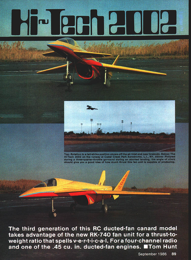
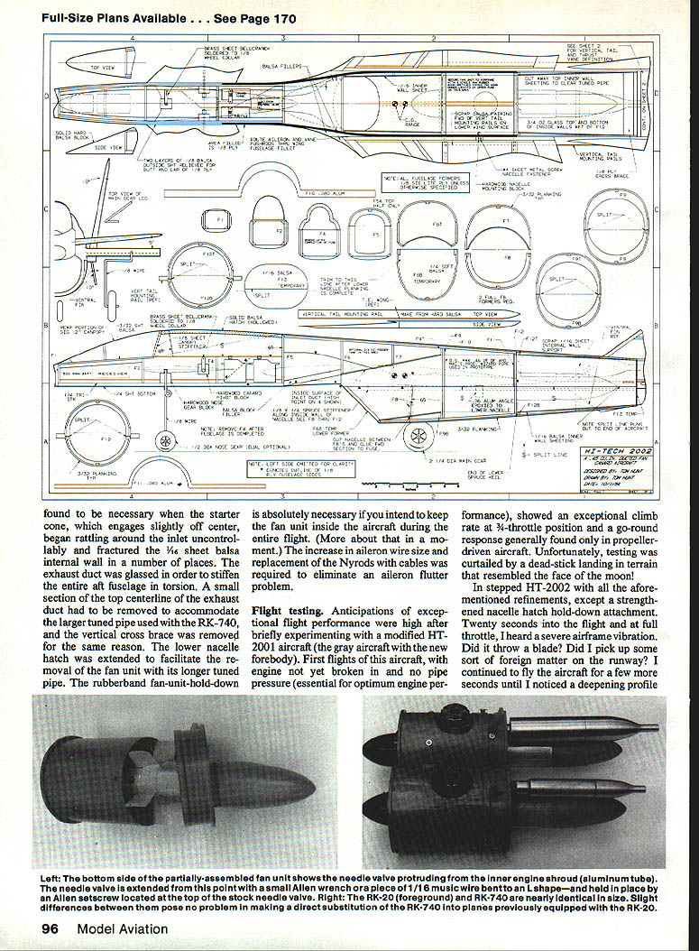
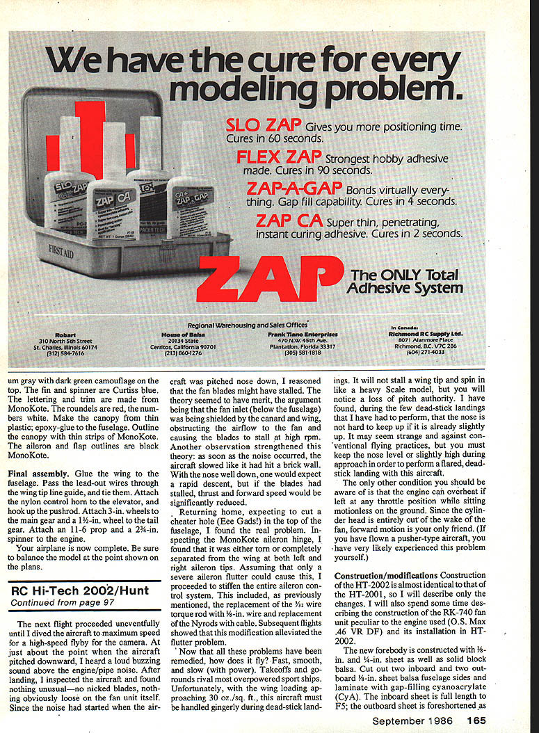
The third generation of this RC ducted-fan canard model takes advantage of the new RK-740 fan unit for a thrust-to-weight ratio that spells vertical. It is designed for a four-channel radio and one of the .45 cu. in. ducted-fan engines.
Do you put .10 engines on 1/2A airplanes, .40s on .20-size airplanes, and .60s on .40s because you really want a "hot" model? If you do, you aren't performing any great feats of magic when your airplane climbs to the stratosphere in seconds. However, when you create an airframe/power plant package in the form of a ducted-fan aircraft that takes off from paved runways in 50 to 80 feet, climbs vertically as long as there is air to breathe, yet slows down to land just like a trainer, that's an accomplishment to be proud of! And that's the Hi‑Tech 2002 and RK‑740 combination; it burns up the sky.
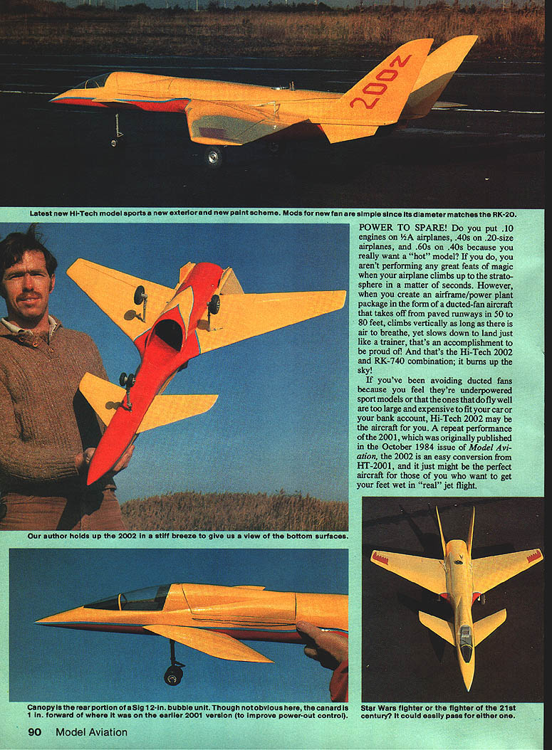
If you've been avoiding ducted fans because you feel they're underpowered sport models or that the ones that do fly well are too large and expensive to fit your car or your bank account, Hi‑Tech 2002 may be the aircraft for you. A repeat performance of the 2001 (originally published in the October 1984 issue of Model Aviation), the 2002 is an easy conversion from HT‑2001, and it just might be the perfect aircraft for those of you who want to get your feet wet in "real" jet flight.
The HT-2001, powered by an RK-20 fan unit with an O.S. Max .25 VR ducted-fan engine, flew well at 4.5 lb., but it did not have jet-like performance. HT-2002 is much improved, not only in the power plant, but also in the new forebody.
HT-2002 development
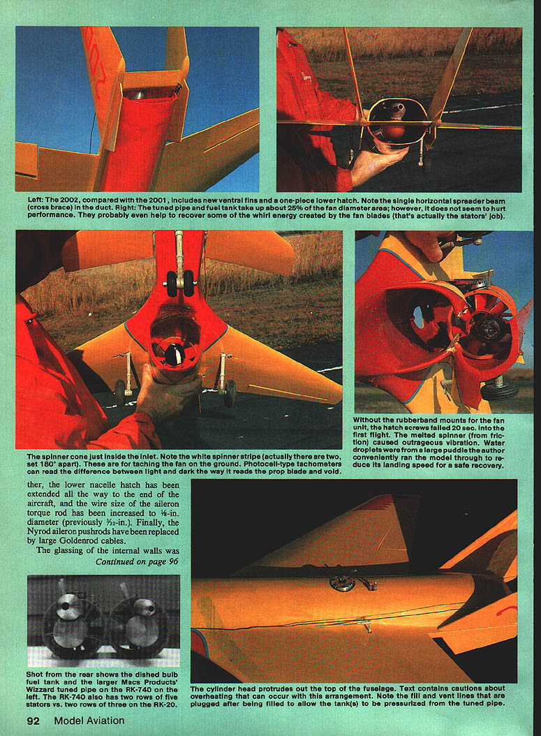
Though not obvious at first glance, a few structural and aerodynamic changes have been incorporated to improve durability and flight performance. Dual ventral fins mounted below the twin vertical tails increase yaw stability at high angles of attack. HT-2001 showed a slight Dutch-roll tendency when the nose was held too high during final approach (a roll-and-yaw rocking motion). This problem in HT-2001 was more an annoyance than a danger, but severe Dutch-roll tendencies can make an aircraft spin out. HT-2002, with the ventral fins added, showed no sign of this phenomenon.
The canard and canard pivot were moved forward 1 in. on the new forebody to improve power-out pitch control. Remember, the thrust-vectoring vane supplements pitch control only while the engine is running.
Structural changes include:
- Epoxy/fiberglassing of all internal duct walls.
- Removal of the top centerline internal 1/16" sheeting in the aft section.
- Inclusion of a rubber-band fan-unit hold-down.
- Removal of the vertical cross brace just forward of the thrust-vectoring vane.
The glassing of the internal walls was necessary when the starter cone, which engages slightly off center, began rattling around the inlet uncontrollably and fractured the 1/16" sheet balsa internal wall in several places. The exhaust duct was glassed to stiffen the entire aft fuselage in torsion. A small section of the top centerline of the exhaust duct had to be removed to accommodate the larger tuned pipe used with the RK-740, and the vertical cross brace was removed for the same reason. The lower nacelle hatch was extended to facilitate removal of the fan unit with its longer tuned pipe. The rubber-band fan-unit hold-down is absolutely necessary if you intend to keep the fan unit inside the aircraft during the entire flight. The increase in aileron wire size and replacement of the Nyrod aileron pushrods with large Goldenrod cables was required to eliminate an aileron flutter problem.
Flight testing
Anticipation was high after briefly experimenting with the modified HT-2001 aircraft (the gray aircraft with the new forebody). First flights were made before the engine was broken in and before pipe pressure (essential to optimum engine performance) was available. The aircraft showed an exceptional climb rate — at full throttle the go-around response was generally similar to that of a propeller-driven aircraft. Unfortunately, initial testing was curtailed by a dead-stick landing on very rough terrain.
After making the aforementioned refinements except for a strengthened nacelle-hatch hold-down attachment, a subsequent flight produced severe airframe vibration 20 seconds at full throttle. A blade was thrown. Foreign matter picked up on the runway was found on the intake, and the aircraft was flown a few seconds longer until a deepening glide profile was noticed.
On another flight with the refinements made, 58 seconds after lift-off the lower nacelle and fan unit began scraping the runway; inspection showed the port-side nacelle hold-down screw was missing and the right-side bracket was broken off the nacelle. MonoKote was the only material bridging the gap, barely holding the front of the nacelle and the fan unit onto the aircraft. The tuned pipe extending past the end of the nacelle had become caught on a horizontal cross brace, which prevented the fan from exiting completely. The weight difference between the RK-740 fan and the RK-20 likely overstressed the two screws securing the nacelle during a high-G turn.
The solution was the rubber-band hold-down. This takes the load off the two #4 sheet-metal screws, which now only secure the lower nacelle — not the fan. With the rubber-band hold-down installed, the fan unit was finally secured to the airframe and HT-2002 returned to the field for more flight testing.
On a later flight, during a high-speed dive for a camera flyby, a loud buzzing sound emerged above the engine/pipe noise and the aircraft slowed abruptly. Initially it was suspected that the fan blades had stalled because the fan inlet (below the fuselage) could be shielded by the canard and wing when the nose was down. However, inspection at home revealed the real problem: the MonoKote aileron hinge was either torn or completely separated from the wing at both left and right aileron tips. Assuming a severe aileron flutter caused this, the entire aileron control system was stiffened: the 3/32-in. wire torque rod was replaced with 1/8-in. wire and the Nyrods were replaced with cables. Subsequent flights showed this modification alleviated the flutter problem.
Now that these problems have been remedied, how does it fly? Fast, smooth, and slow (with power). Takeoffs and go-arounds give almost overpowering sport-ship performance. With the wing loading approaching 30 oz./sq. ft., the aircraft must be handled gingerly during dead-stick landings. It will not stall with a wingtip and spin like a heavy scale model, but you will notice a loss of pitch authority. During dead-stick landings, keep the nose level or slightly high during approach to perform a proper flare; this is contrary to some conventional practices but works for this airframe.
One other condition to be aware of: the engine can overheat if left at any throttle position while sitting motionless on the ground. Since the cylinder head is entirely out of the wake of the fan, forward motion is necessary for cooling. (If you have flown a pusher-type aircraft, you have likely experienced this problem.)
Construction/modifications
Construction of the HT-2002 is almost identical to the HT-2001; the following describes only the changes and the installation of the RK-740 fan unit with the O.S. Max .46 VR DF engine.
Forebody and fuselage
- The new forebody is constructed with 1/8- and 1/4-in. sheet as well as solid balsa block. Cut out two inboard and two outboard 1/8-in. sheet balsa fuselage sides and laminate with gap-filling cyanoacrylate (CyA). The inboard sheet is full length to F5; the outboard sheet is foreshortened as required to fair into the canopy. Glue these to the top longerons and install the top 1/8-in. sheet. Carve and sand the forebody to shape. Mount the cowl ring to the fuselage then carefully fit the cowl to the ring.
- Per the plan, cut out the fuselage bottom from 1/4-in. hard balsa to the exact shape and length shown. Glue the 1/4-in. triangle stock to the laminated side walls. Lay the bottom sheet over the plan, then cut out and glue F1 through F4 to the bottom sheet, centering each former across the width of the bottom sheet.
- Glue the fuselage side walls to the formers and bottom sheet, making sure the shorter 3/8-in. wall sheet is to the outside (this is for the lap joint to the existing 1/8-in. Lite Ply fuselage on HT-2001). If building a new HT-2002, make the outside fuselage wall full length from 1/8-in. Lite Ply, lapping a 1/8-in. sheet balsa inside wall to the 3/8-in. ply outside wall. Add the 3/32-in. sheet balsa canopy floor to the forward top 1/4-in. triangle stock.
- Block up the nose and hatch pieces on sheet balsa or solid block and glue in place. Cut the HT-2001 nose off at the old F4 bulkhead (remove your radio first). Cut the 1/8-in. Lite Ply fuselage wall to the shape shown on the plans, and remove any balsa planking from the fuselage top for F5. Secure the new nose onto the HT-2001 to create the HT-2002 forebody.
- For a new-build HT-2002, create the forebody in conjunction with the rest of the fuselage above the nacelle/fuselage split line. Carve and sand the forebody to match the HT-2001 contour at F5. Cut away the radio hatch from the fuselage walls, leaving a small angled portion just behind the canopy. Hollow F2 to fit your radio into the nose, and remove F4 entirely if it interferes with radio installation.
- Add hardwood canard and nose gear pivot blocks. The radio hatch can be secured with a 1/16-in.-dia. pin in the aft section that protrudes into F5 and a sliding pin mounted on the fixed piece just behind the canopy. The sliding pin can work loose while the engine is running, so secure it with a small piece of tape before flying.
Canopy and finishing
- The canopy is taken from the rear portion of a 12- or 13-in. Sig bubble canopy or is available from hobby shops or direct from Sig. Do not glue the canopy; trim it for a close fit and secure with matching-color trim MonoKote. Heat the trim MonoKote with an iron for a better seal with both the acetate and the underlying MonoKote.
- The small ventral fins are cut from 1/8-in. sheet balsa and secured to the bottom center of the vertical tail-mounting rails with CyA. Angle the vents out about 10° from the lower nacelle (the same as the vertical tails) to improve ground clearance and airflow over the inboard side.
Wings, tails, and control surfaces
- No changes were made to the wings except for deletion of the wing-tip sidewinders (they frequently broke off on rough runways), which did not affect flight performance.
- The vertical tails and canard remain the same, but the fuselage must be modified to accept the new fan unit: cut a larger hole in the top deck for the cylinder head; cut out an area in the inside upper inner wall for the tuned pipe (see plans); remove the vertical support brace; and depending on the engine used, either shorten or lengthen the throttle pushrod. These modifications take only a few hours.
- Tail feathers and control surfaces are built and sheeted as on the HT-2001. All flight surfaces are sealed and covered with MonoKote. Elevators and rudder are hinged with CA hinges and the ailerons use inboard-mounted servos with pushrods converted to cable where necessary for stiffness.
Nacelles and fan unit installation
- The nacelles are built from 1/8-in. formers with 1/16-in. sheet tops. The lower nacelle is removable and secured with screws to allow installation and removal of the fan unit. The RK-740 fan unit is assembled on a plywood bulkhead that bolts to the rear former of the nacelle; this bulkhead also locates the tuned pipe. The tuned pipe protrudes slightly aft of the nacelle to help retain the fan unit in case of a partial nacelle separation.
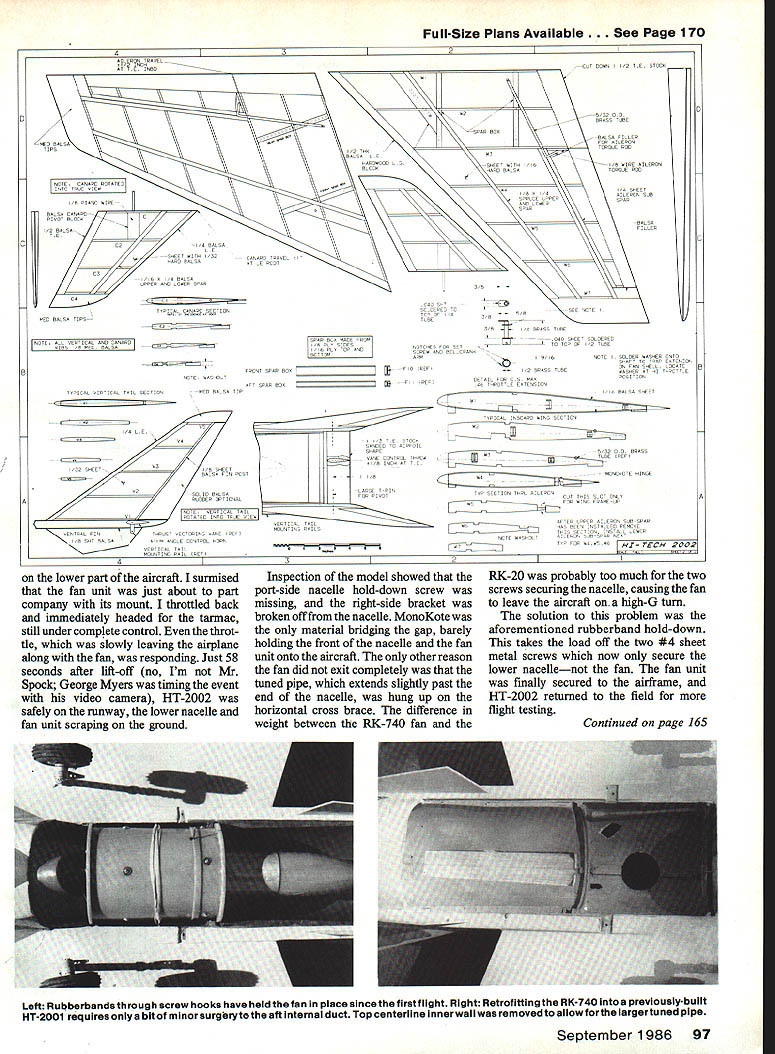
- The fan unit installation requires careful alignment of the engine, spinner backplate, and the fan. The needle valve on the carburetor must be accessible; extend the needle-valve button with a short piece of aluminum tubing so that a small Allen wrench or a piece of 1/16-in. music wire bent to shape can adjust it from the nacelle opening.
- A rubber-band hold-down for the fan unit is absolutely necessary if you intend to keep the fan unit inside the aircraft during the entire flight.
The RK-740 fan unit and installation details
The RK-740 fan unit is an impressive engineering achievement. Bob Kress of Kress Technology has designed a fan much smaller in diameter than its competitors yet offering similar thrust output (approximately 7 lb.). The primary intent was to maintain the same size as the RK-20, and except for the necessary addition of a longer and larger-diameter tuned pipe, the unit closely matches the RK-20. The RK-740 can be retrofitted with very few modifications into any aircraft designed for an RK-20.
At the time of this writing, three engine choices are possible without further modification: the K&B front and rear rotor 7.5cc and the O.S. Max .46 VR DF. When ordering, specify the intended engine.
If using the O.S. Max .46 VR DF:
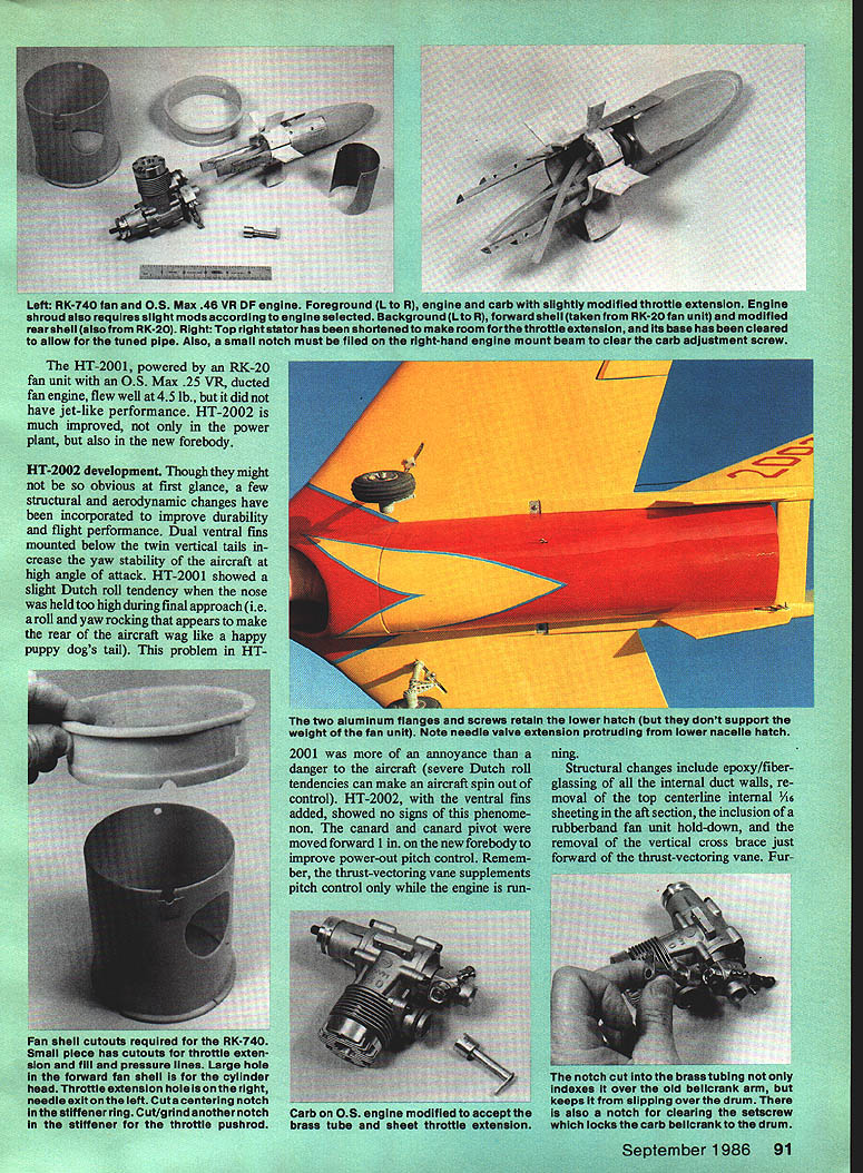
- When assembling the engine/carburetor to the engine mount, grind a semicircular relief in the right-hand beam for the carburetor idle-stop screw. Grind about 1/32 in. deep with a 3/16-in. dia. grinding tool. Chamfer the beams on the top slightly to fit the slightly greater width of the O.S. vs. the K&B. File washers under the engine bolts flush with the beams so they do not interfere with the aluminum shroud of the engine body.
- If using a dished fuel tank (necessary with Mac's Products Wizzard tuned pipe), provide a vent/pressure line to the top of the tank. One solution is a piece of curved 3/32-in. O.D. brass tubing inserted into the top of the tank nipples and positioned to reach the top surface of the dished tank, then hot-stuffed into place from the inside. Note: the dished tank has approximately a 6-oz. capacity — not much fuel for a .46 cu. in., in-line, high-rpm fan engine. Expect about three minutes of high-speed flight with very little fuel reserve; consider a 2- to 4-oz. feeder tank in the aft radio section to supplement the integral tank. Pipe pressure may feed the main tank from this auxiliary tank.
- A throttle extension shaft must be fabricated to get the bellcrank outside the fan shell. This is made from brass tubing and sheet brass in about an hour; details are on the plans. Provide a hole to access the speed-carburetor adjustment screw located on the bellcrank side of the carburetor. File the stock black steel bellcrank arm to the same diameter as the drum to fit the throttle extension; file the two notches on the brass extension for the bellcrank and the drum setscrew. Position the brass external bellcrank correctly for proper throttle actuation. When assembly is complete, shorten the top right aft stator chord from the leading edge to accommodate the throttle extension shaft.
- To ease retrofit into HT-2001, a gated RK-20 fan shell was used for the RK-740 instead of the aluminum wrap provided in the kit. If you cannot get a fan shell from Midwest or Kress Technology, use the stock shell and position plywood rings on the front and aft ends to simulate the RK-20.
- A hole and setscrew in the needle valve allow extension of the needle valve outside the fan shell and nacelle using piano wire or an Allen wrench. A 1/16-in.-dia. L-shaped wire works well.
- Drill or enlarge holes for the cylinder head, needle valve, fuel lines, and throttle extension as required. Cut notches in the fan shell for the throttle pushrod and the forward stiffener ring notch for alignment in the fuselage. Trial-fit the fan assembly into the aircraft and locate a hole in the lower nacelle half for the needle valve.
Charge the batteries, truck to the field, fuel it, fire it up, set it on the threshold, push the throttle to the firewall, pull the stick into your chest, and watch it point its nose toward the heavens.
Till next sortie . . .
Acknowledgments Again I would like to thank George Myers, Bob Kress, Bob Aberle, and especially my wife (proofreader and moral support) for their help in making this project a pleasant and painless success.
When responding to advertisers, mention that you read about them in Model Aviation.
Transcribed from original scans by AI. Minor OCR errors may remain.

