
A. G. Lennon
HIGH-LIFT DEVICES FOR MODELS
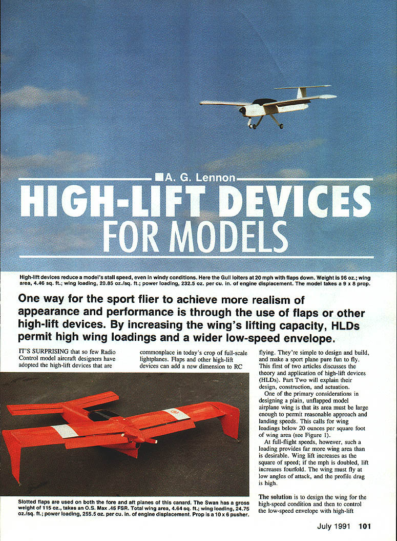
One way for the sport flier to achieve more realism of appearance and performance is through the use of flaps or other high-lift devices (HLDs). By increasing the wing's lifting capacity, HLDs permit higher wing loadings and a wider low-speed envelope.
It's surprising that so few radio-control model aircraft designers have adopted the high-lift devices that are commonplace on today's full-scale lightplanes. Flaps and other HLDs can add a new dimension to RC flying. They're simple to design and build, and make a sport plane pure fun to fly.
This first of two articles discusses the theory and application of high-lift devices. Part Two will explain their design, construction, and actuation.
Theory and application
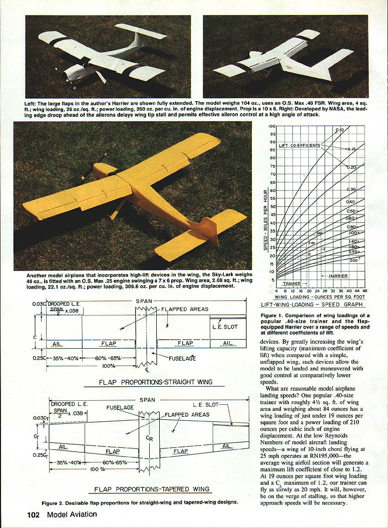
One of the primary considerations in designing a plain, unflapped model airplane wing is that its area must be large enough to permit reasonable approach and landing speeds. This calls for wing loadings below about 20 ounces per square foot of wing area (see Figure 1).
At full-flight speeds, however, such a loading provides far more wing area than is desirable. Wing lift increases as the square of speed; if the speed is doubled, lift increases fourfold. The wing must fly at low angles of attack, and profile drag is high.
The solution is to design the wing for the high-speed condition and then to control the low-speed envelope with high-lift devices. By greatly increasing the wing's lifting capacity (maximum coefficient of lift, Cmax) compared with a simple, unflapped wing, such devices allow the model to be landed and maneuvered with good control at comparatively lower speeds.
What are reasonable model landing speeds?
One popular .40-size trainer with roughly 4½ sq. ft. of wing area and weighing about 84 ounces has a wing loading of just under 19 oz/ft² and a power loading of 210 ounces per cubic inch of engine displacement. At the low Reynolds numbers of model aircraft landing speeds—a wing of 10‑inch chord flying at 25 mph operates at Re ≈ 195,000—the average wing airfoil section will generate a maximum lift coefficient close to 1.2. At 19 oz/ft² wing loading and a Cmax of 1.2, our trainer can fly as slowly as 20 mph. It will, however, be on the verge of stalling, so higher approach speeds will usually be necessary.
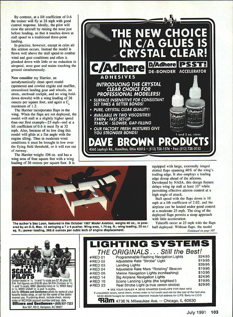
In contrast, a trainer with Cmax ≈ 0.6 will fly at 28 mph with good control response. Ideally the pilot will slow the aircraft, raise the nose just before landing, and touch down at stall speed in the traditional three-point landing practice. However, except in calm air, this seldom occurs. Instead, the model is often flown well above stall speed to combat wind gusts or is put down with little or no reduction in airspeed, nose gear and mains touching the ground simultaneously.
Model example: the Harrier
Now consider the Harrier, an aerodynamically clean sport model (spinner, cowled engine and muffler, streamlined landing gear and wheels, no struts, enclosed cockpit, and no wing hold-down dowels) with a wing loading of 26 oz/ft² and a Cmax of 1.2.
The Harrier incorporates flaps. When the flaps are not deployed, the model will stall at a slightly higher speed than our first example—about 23 mph—and at a lift coefficient of 0.6 it must fly at 32 mph. Also, because of its low drag this model will glide at a flat angle with the engine idling. Thus in moderate wind conditions it must be brought in low over the flying-field threshold, or it will run out of runway.
The Harrier weighs 104 oz and has a wing area of 4 sq ft, giving a wing loading of 26 oz/ft². It is equipped with large, externally hinged slotted flaps spanning 60% of the wing's trailing edge. It also employs a leading-edge droop ahead of the ailerons. Developed by NASA, this design feature delays wing-tip stall by at least 10° while permitting effective aileron control at high angles of attack.
With the flaps down, stall speed is 18 mph at a lift coefficient of 2.02, and the airplane can be landed under good control at a moderate 25 mph. The drag of the deployed flaps permits a steep approach with little acceleration. Takeoffs occur at 25 mph with the flaps half deployed. With the flaps retracted the Harrier would have to accelerate to around 35 mph and would have a lower rate of climb.
These flaps are rugged; they may be lowered partially or fully at any point in the model's flight. Turning maneuvers and loops are very tight with the flaps down.
The Harrier has been flown repeatedly in windy conditions. With flaps down, nose up trim, and engine throttled back, the model hovers with little ground speed yet remains under good control. Fellow fliers are surprised that it doesn't stall and fall off into a spin.
When powered by an O.S. Max .40 FSR engine turning a 10×6 propeller, the plane takes off and climbs more ably than most .40‑powered ships of lesser weight. It also has a wider speed range and is capable of all the aerobatics in the book.
Under strong wind conditions, however, it's best to use little or no flap. Because the higher wing loading exerts a beneficial effect, airspeed increases and penetration and control are improved. Bear in mind that landing into the wind slows the model, reducing its ground speed and steepening the approach.
Flap handling and pilot technique
Many pilots have reservations about flying models equipped with flaps. One reason is that when the flaps are lowered the model pitches sharply upward, even at low speed. My friend and fellow club member Dick Murray cleverly avoids this by applying elevator-down trim to neutralize the upward pitch as he lowers the flaps. The Harrier continues in level flight and becomes noticeably slower.
High-lift devices, then, permit higher wing loadings and moderate maneuvering and landing speeds. While these devices together with their servos and linkages will add about six or seven ounces to the model's weight, that's far from bridging the 20‑oz differential between the 80‑oz trainer and the 104‑oz Harrier.
Beneficial weight may be added by:
- larger spinners
- enclosed and ducted engine and muffler cowlings
- rounded fuselages
- landing gear strut fairings
- wheel pants
- fully faired, sheeted, stress-skinned, more rugged structures
- higher-capacity receiver batteries
- larger fuel tanks
Models equipped with HLDs are more versatile, more rugged, and much more fun to fly. They're well worth the extra work and cost (materials, transmitter, servos, etc.) involved in making them.
Larger quarter-scale models, which normally fly faster, would also benefit from HLDs. Figure 2 shows desirable flap proportions for both straight and tapered wings.
Part Two will discuss the design, construction, and actuation of high-lift devices.
Transcribed from original scans by AI. Minor OCR errors may remain.

