
The Hiliner
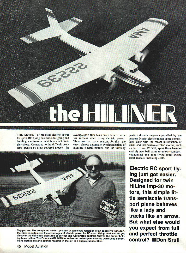
The advent of practical electric power for sport RC flying has made designing and building multi-motor models a much simpler chore. Compared to the difficult problems created by glow-powered models, the average sport flier has a much better chance for success when using electric power. There are two basic reasons for this—the easy, almost automatic synchronization of multiple electric motors, and the virtually perfect throttle response provided by the modern MOSFET electric motor speed controllers. Now with the recent introduction of small and inexpensive electric motors, such as the HiLine IMP-30, sport fliers have an entirely new ball game to enjoy—compact, economical and good-flying multi-engine sport models, including scale.
Electric RC sport flying just got easier. Designed for twin HiLine IMP-30 motors, this simple little semiscale transport plane behaves like a lady and tracks like an arrow. But what else would you expect from full and perfect throttle control? — Don Srull
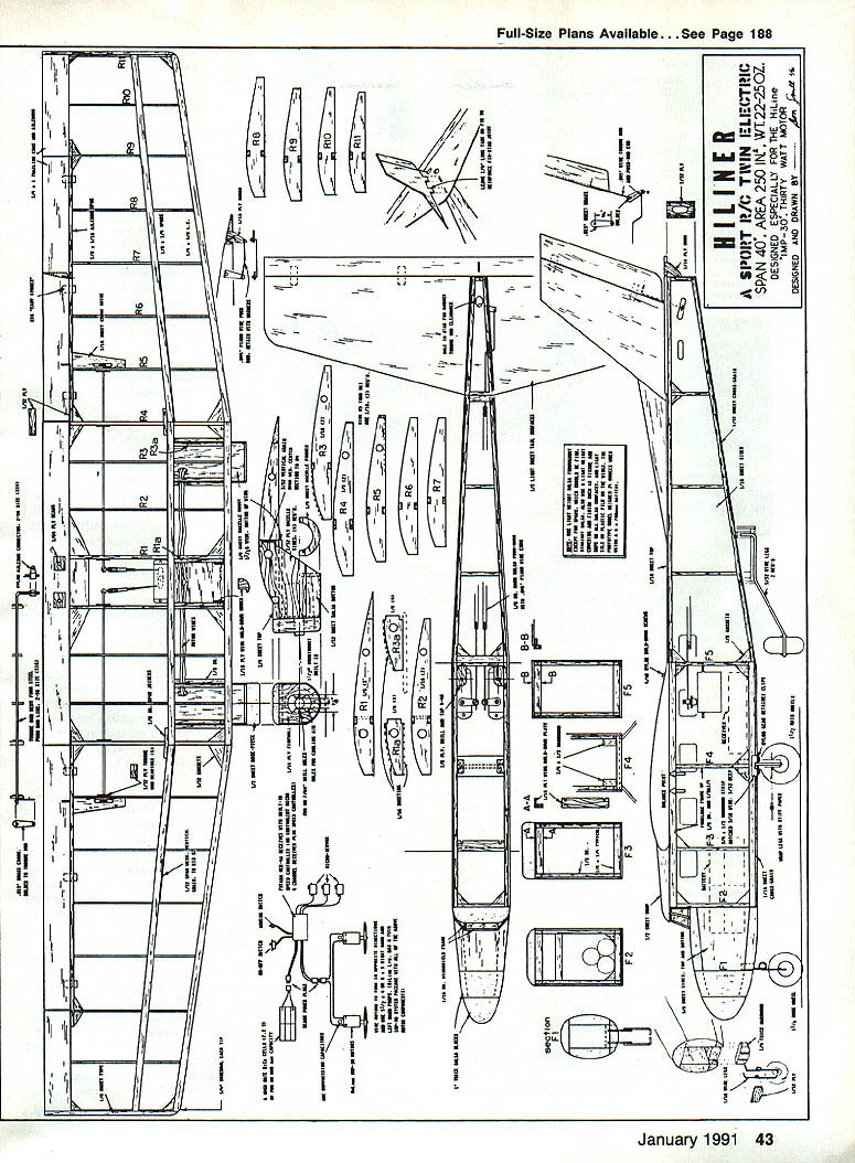
To learn a little about this new class of sport flier I set out to design a small, simple twin-motored model especially sized for the HiLine IMP-30. Wing area was set at 250 sq in, span 40 in, target gross weight 20–25 oz. A stable shoulder-wing configuration was selected, as well as an easy sheet-balsa fuselage and tail construction and trike gear. Sketched early design doodles soon produced a sleek-looking semiscale rendition of an executive transport.
An Aerocommander model has IMP-30 motors turning 5 x 4 props in opposite directions to eliminate torque effects—a nice feature. The little motors run on three cells wired in series; therefore two motors require a six-cell battery. 700 mAh–800 mAh capacity battery choices are common; six-cell battery packs are readily available and easy to charge. Simple field chargers are available today.
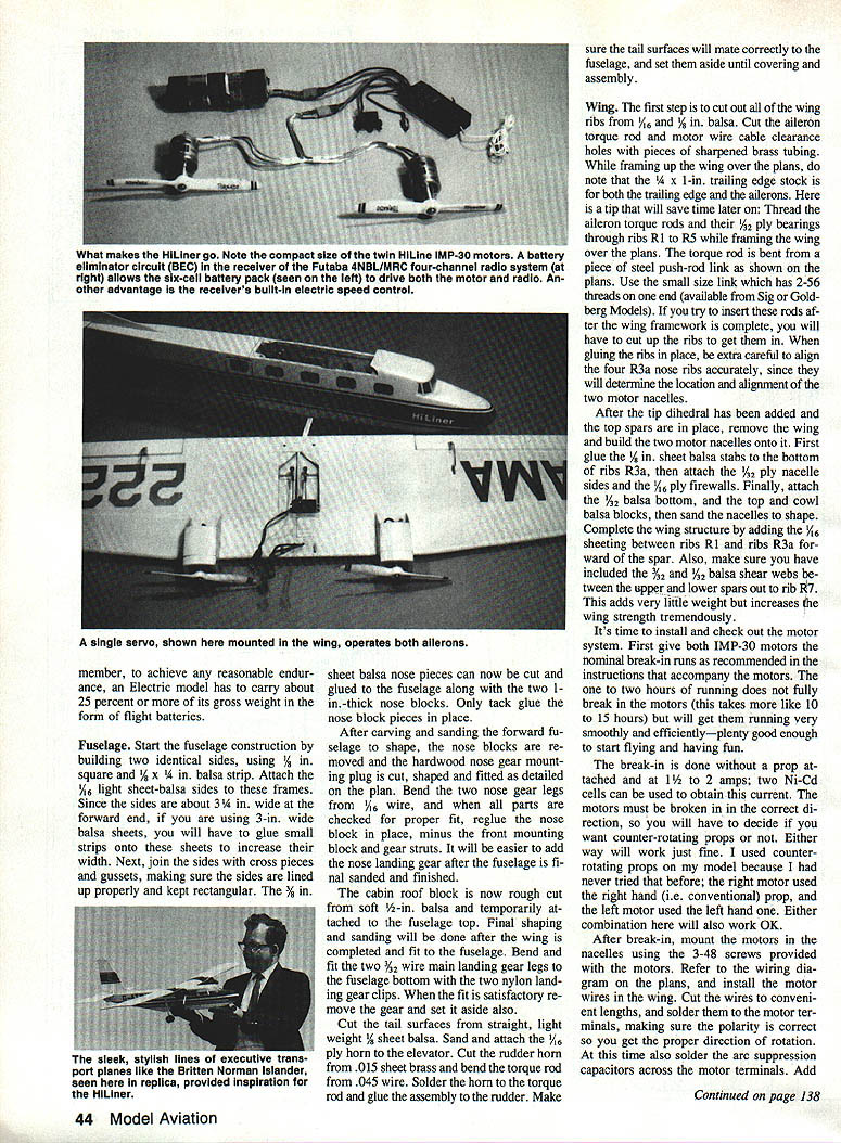
The six-cell arrangement also allows use of the very convenient Futaba 4NBL/MRC four-channel radio system that has its own speed control built into the receiver. The receiver also has a battery eliminator circuit (BEC) built in, which means the radio system works off the motor battery and does not require its own four-cell battery pack. Several other very good mini four-channel radios are also suitable for compact electric models, including the Airtronics VG4R system, which uses a separate speed control.
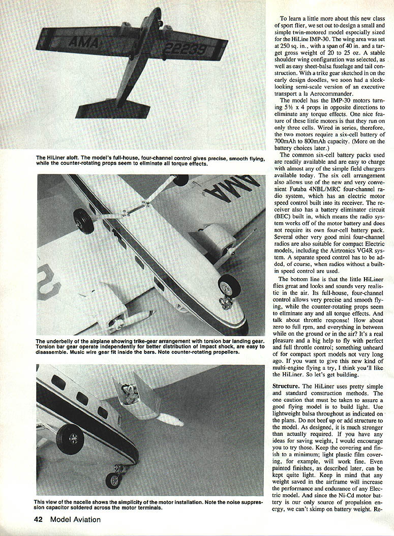
Bottom line: the HiLiner flies great, looks and sounds realistic in the air, and is a supple, honest flier. Its full-house four-channel control allows very precise, smooth flying. Counter-rotating props seem to eliminate torque effects. Talk about throttle response—from about zero to full RPM and everything between on the ground and in the air, it's a real pleasure. Big help is the perfect full-throttle control, something unheard of on compact sport models until very recently. If you want to give this new kind of multi-engine flying a try, I think you'll like the HiLiner. So let's get building.
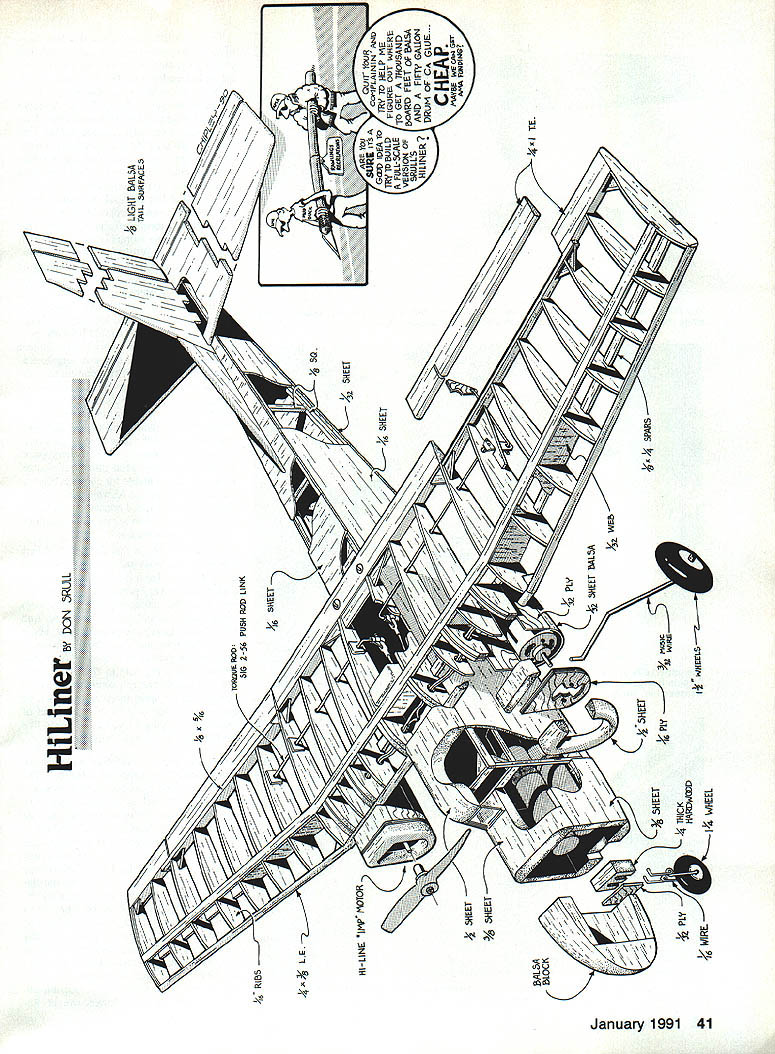
Structure
HiLiner uses pretty simple, standard construction methods. Caution must be taken to assure a good flying model—build light. Use lightweight balsa throughout as indicated on the plans; beef up or add structure where required. As designed, the model is much stronger than actually required. If you have ideas for saving weight, I would encourage you to try them. Keep covering and finish to a minimum; light plastic film covering, for example, will work fine. Painted finishes described later can be kept quite light. Keep in mind that weight saved in the airframe will increase performance and endurance.
Since the Ni-Cd motor battery is our only source of propulsion energy, we can't skimp on battery weight. Remember that a 700 to 800 mAh six-cell pack mounted near the CG will be about 7 to 8 oz. Do not try to use smaller packs, or you will sacrifice both power and endurance. The motors will pull about 6 to 7 amps each at full throttle, so be sure your battery pack can deliver 12 to 14 amps continuous. Mount the pack so the CG is correct; you may have to add a small amount of nose weight to obtain the proper balance.
Remember, to achieve any reasonable endurance, an electric model has to carry about 25 percent or more of its gross weight in the form of flight batteries.
Fuselage
Start the fuselage construction by building two identical sides, using 1/8 in. square and 1/8 x 1/4 in. balsa strip. Attach the 1/16 in. light sheet-balsa sides to these frames. Since the sides are about 3/4 in. wide at the forward end, if you are using 3-in. wide balsa sheets, you will have to glue small strips onto these sheets to increase their width. Next, join the sides with cross pieces and gussets, making sure the sides are lined up properly and kept rectangular. The 3/8 in. sheet balsa nose pieces can now be cut and glued to the fuselage along with the two 1/8 in.-thick nose blocks. Only tack-glue the nose block pieces in place.
After carving and sanding the forward fuselage to shape, the nose blocks are removed and the hardware nose gear mounting plug is cut, shaped and fitted as detailed on the plan. Bend the two nose gear legs from 1/16 in. wire, and when all parts are checked for proper fit, reglue the nose block in place, minus the front mounting block and gear struts. It will be easier to add the nose landing gear after the fuselage is final sanded and finished.
The cabin roof block is now rough cut from soft 1/2 in. balsa and temporarily attached to the fuselage top. Final shaping and sanding will be done after the wing is completed and fit to the fuselage. Bend and fit the two 3/32 in. wire main landing gear legs to the fuselage bottom with the two nylon landing gear clips. When the fit is satisfactory remove the gear and set it aside also.
Cut the tail surfaces from straight, lightweight 1/8 in. balsa. Sand and attach the 1/16 in. ply horn to the elevator. Cut the rudder horn from .015 in. sheet brass and bend the torque rod from .045 in. wire. Solder the horn to the torque rod and attach the assembly to the rudder. Make sure the tail surfaces will mate correctly to the fuselage, and set them aside until covering and assembly.
Wing
The first step is to cut out all of the wing ribs from 1/8 and 1/16 in. balsa. Cut the aileron torque rod and motor wire cable clearance holes with pieces of sharpened brass tubing. While framing up the wing over the plans, note that the 1/4 x 1-in. trailing edge stock is for both the trailing edge and the ailerons. Tip: thread the aileron torque rods and their 1/2 in. ply bearings through ribs R1 to R5 while framing the wing over the plans. The torque rod is bent from a piece of steel push-rod wire and is shown on the plans. Use the small size link which has two 2-56 threads on one end (available from Sig or Goldberg Models). If you try to insert these rods after the wing framework is complete, you will have to cut up the ribs to get them in. When gluing the ribs in place, be extra careful to align the four R3a nose ribs accurately, since they will determine the location and alignment of the two motor nacelles.
After the tip dihedral has been added and the top spars are in place, remove the wing and build the two motor nacelles onto it. First glue the 1/8 in. sheet balsa stabs to the bottom of ribs R3a, then attach the 1/8 in. ply nacelle sides and the 1/16 in. ply firewalls. Finally, attach the 1/2 in. balsa bottom, and the top and cowl balsa blocks, then sand the nacelles to shape. Complete the wing structure by adding the 1/16 in. sheeting between ribs R1 and ribs R3a forward of the spar. Also, make sure you have included the 3/32 in. and 1/32 in. balsa shear webs between the upper and lower spars out to rib R7. This adds very little weight but increases the wing strength tremendously.
It's time to install and check out the motor system. First give both IMP-30 motors the nominal break-in as recommended in the instructions that accompany the motors. The one to two hours of running does not fully break in the motors (this takes more like 10 to 15 hours) but will get them running very smoothly and efficiently—plenty good enough to start flying and having fun.
The true break-in is done without a prop attached and at 1 1/2 to 2 amps; two Ni-Cd cells can be used to obtain this current. The motors must be broken in in the correct direction, so you will have to decide if you want counter-rotating props or not. Either way will work just fine. I used counter-rotating props on my model because I had never tried that before; the right motor used the right-hand (conventional) prop, and the left motor used the left-hand one.
After break-in, mount the motors in the nacelles using the 3-48 screws provided with the motors. Refer to the wiring diagram on the plans, and install the motor wires in the wing. Cut the wires to convenient lengths, and solder them to the motor terminals, making sure the polarity is correct so you get the proper direction of rotation. At this time also solder the arc suppressor capacitors across the motor terminals. Add your favorite connector to the end of the cable that exits from the wing into the fuselage. The new Dean Power Plug (sold by ACE R/C and HiLine Ltd.) is a very compact and efficient connector, just perfect for small electric RC use. Attach both props—either 5 1/2 x 4 or 6 x 3—to the motors, and give them a test run to make sure everything is OK. Don't overdo the test running on fully charged batteries since the current draw will be higher than in flight (it should be between 1.0 and 1 1/2 amps during break-in), and the cooling is not as good as it will be in the air.
Radio system. First coat the inside of the fuselage sides with epoxy in the area where the two miniservos for rudder and elevator will be located. This will harden and smooth out the balsa, providing a good surface for the double-sided foam tape that will be used to mount the servos. Make up the two pushrods from hard 1/8-in. square balsa and .045 in. wire. Install the aileron servo up against the rear of the main spar using double-sided foam tape, and make up the short pushrods that attach to the 2-56 threaded nylon servo connectors. The aileron bellcranks are cut from .015 in. sheet brass, drilled and soldered to the torque rods. Align the torque rods and bellcranks, and tack-glue the 3/32 ply torque rod bearings onto the appropriate ribs. Take care not to get glue inside the bearing holes! Make sure the aileron controls work smoothly and properly. Temporarily hook up the radio, charge the batteries and test the whole system, including the motors. If all is OK we are ready for covering and assembly.
Covering and finishing
Use your favorite covering method, but keep it light. Any of the plastic films will work fine. Since I prefer a painted finish on my models, I covered all balsa surfaces with light tissue (Polyspan) after brushing a few coats of nitrate dope on the bare wood. The wing was then covered with light silk (or, if you prefer, clear film is a good, lightweight substitute). All surfaces were then sealed with two thin coats of clear nitrate dope.
Before color dope is applied, the tail surfaces are glued in place, and the hinged control surfaces are attached. I highly recommend Sig (RC)'s new Easy Hinges. For small models like the HiLiner, they are very easy to install and do the job nicely. I cut the hinge pieces into 1/4-in. wide strips to make installation simpler and to get better flex than full-width hinges would provide. After assembly is complete, airbrush on a couple of thin coats of Dianna Cream butyrate dope overall. When dry, mask the trim stripes and airbrush a thin coat of metallic green dope. A few pieces of 1/8-in.-wide red trim tape provide the final touch to a very light painted finish.
Flying
Let's first discuss batteries. As the saying goes, there are batteries, and then there are batteries. I can't emphasize too much the importance of good, properly sized flight batteries. There is no other way to get decent flight performance out of electric RC models. Old batteries from worn-out radio gear or second-hand packs won't do the job. Use fresh, low internal-resistance Ni-Cd packs. The motors will draw more current on the ground than in the air, so be sure your packs are up to the task.
Hand or surplus batteries of unknown origin are not worth fooling with. And it just won't work to make up for an overweight airframe by saving on battery weight. To help you get off on the right track, here are two specific batteries that are sized right for twin IMP-30 models, and that I know will work very well:
- A six-cell Sanyo 700AR pack weighs 6.0 oz and will give full-power flight times of four to five minutes.
- A six-cell Sanyo 800AR pack weighs 6.9 oz and will give full-power flight times of five to six minutes.
The Sanyo AR-type cells are high-rate, low internal-resistance cells made for very high-current applications like electric models. They are rugged, easy to charge, and will last a long time if properly taken care of. If you are a relative beginner in electric flying, I recommend you start with either of these packs. Later, you can explore other sizes and types of batteries, but these will be a good point of departure.
To help you get started in small twin electrics, HiLine Ltd. is temporarily offering a twin IMP-30 system package at a price of $64.95 plus $5.00 postage and handling. It includes two motors, a Sanyo 800AR six-cell battery pack, two Dean Power Connector sets, two 5 1/2 x 4 props (for counter-rotation), switch, suppression capacitors, and hook-up wire. It's seven bucks under the usual price and can save you time searching out all the right parts. Write HiLine at P.O. Box 1283, Bethesda, MD 20827.
Before test flying begins, make a few last-minute checks. If there are any warps in the flying surfaces, get them out by steaming or applying heat with a MonoKote iron. I would also recommend trimming both ailerons with about 1/8 in. of up. This provides some effective washout in the wing, helping to reduce tip stall tendencies. Check the balance point and shift the batteries as necessary to get it in the range shown on the plans.
If at all possible, try the first test flights by taking off from a flat, smooth surface. Our first flights were from a blacktop access road near a parking lot. Make sure control movement is in the correct direction and that the model tracks straight under power. When all seems well, slowly bring up full throttle and let the little HiLiner accelerate, using rudder to keep it tracking straight. Feed in a very small amount of up elevator, and let her take off when she's ready.
Keep it in a shallow, fast climb. Above all, don't try to horse the model off the ground early or let it climb out at a steep angle with nose high and airspeed low. Keep the speed up and let the model climb to 100 feet or so before feeling it out. Correct any yawing tendencies with rudder trim and any roll with aileron trim. Set the elevator trim so that at high cruise speed the model shows no climbing or diving tendencies. With the center of gravity in the right spot the HiLiner should behave like a lady and track like an arrow.
After gaining some altitude, throttle back and test its low-speed behavior. At full throttle, try some modest maneuvers like loops and wingovers. If you are using a radio with BEC, remember to think ahead: as the power begins to diminish, the automatic motor shutoff will be approaching. You can soon learn to gauge how long a flight you can expect to make with a fully charged battery pack and still come back in with power before the automatic shutoff occurs.
I think you will enjoy the HiLiner if you give it a try. Just keep the total weight below 25 ounces, and you will be able to experience simple, practical and highly reliable multiengine flying. On top of all that, the HiLiner is quiet, greaseless and economical. Careful, though— it may be habit forming.
Transcribed from original scans by AI. Minor OCR errors may remain.

