
Hiperbipe
Charles Schobloher
Introduction
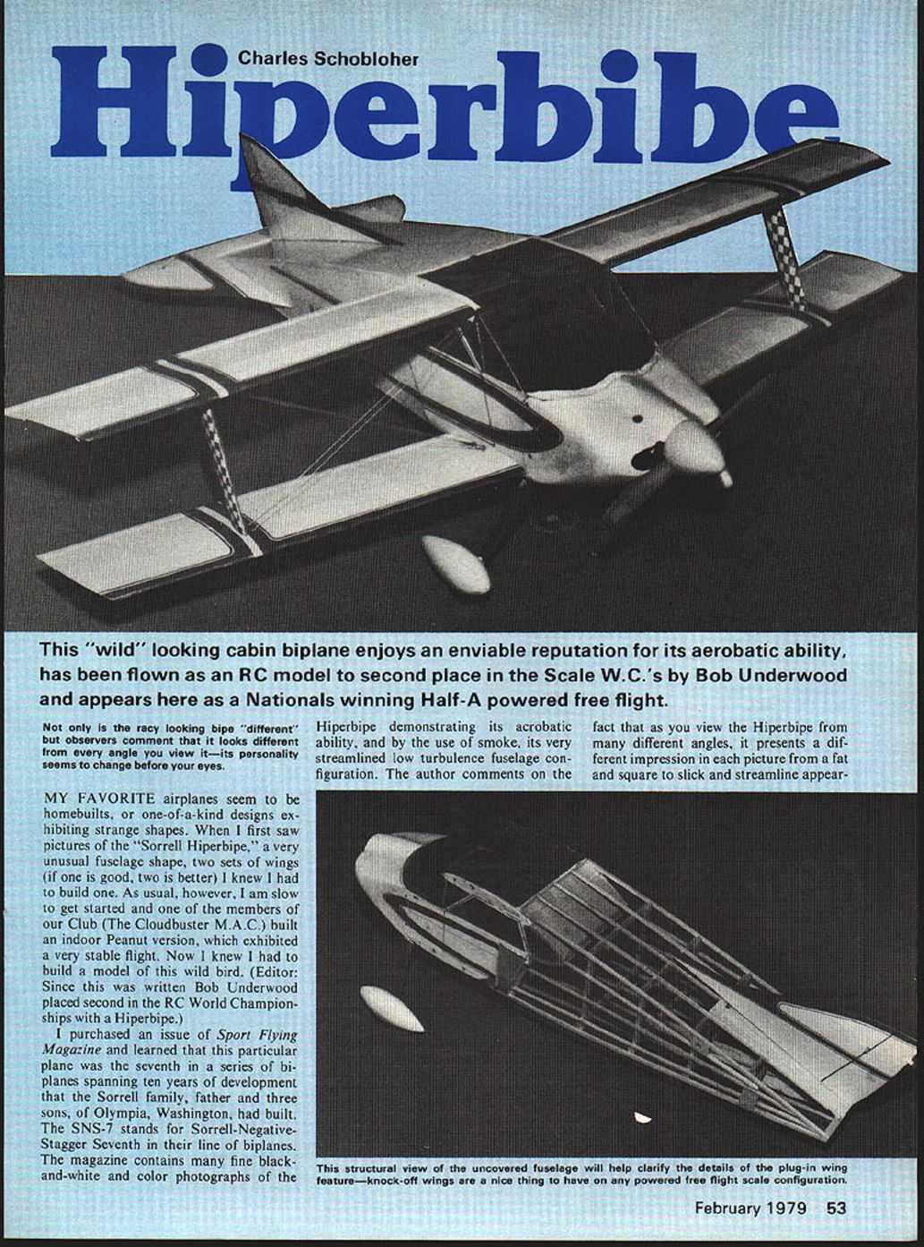
Not only is the racy-looking biplane different, observers comment that it looks different from every angle you view it—its personality seems to change before your eyes.
My favorite airplanes seem to be homebuilts or one-of-a-kind designs exhibiting strange shapes. When I first saw pictures of the Sorrell Hiperbipe — a very unusual fuselage shape with two sets of wings — I knew I had to build one. As usual, however, I was slow to get started and one of the members of our club (The Cloudbuster M.A.C.) built an indoor Peanut version, which exhibited very stable flight. Now I knew I had to build a model of this wild bird. (Editor: Since this was written Bob Underwood placed second in the RC World Championships with a Hiperbipe.)
I purchased an issue of Sport Flying magazine and learned that this particular plane was the seventh in a series of biplanes spanning ten years of development that the Sorrell family (father and three sons) of Olympia, Washington, had built. The SNS-7 stands for Sorrell-Negative-Stagger Seventh in their line of biplanes. The magazine contains many fine black-and-white and color photographs of the Hiperbipe demonstrating its acrobatic ability, and by the use of smoke, its very streamlined low-turbulence fuselage configuration. The author comments that as you view the Hiperbipe from many different angles, it presents a different impression in each picture, from fat and square to slick and streamlined.
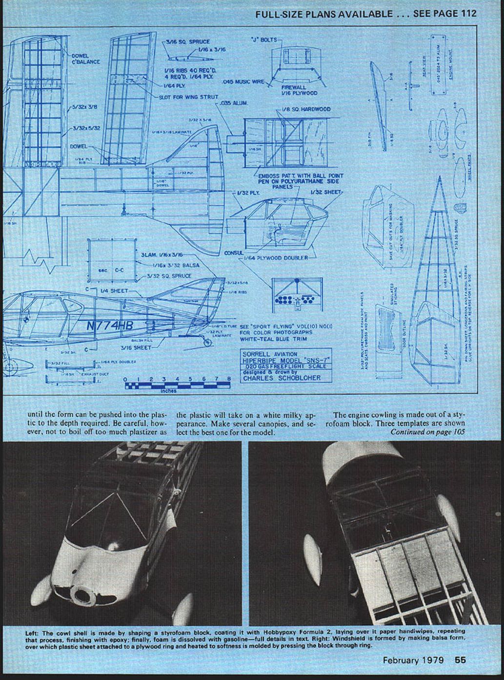
The magazine also included a 3-view that I used in drawing up the plans for the model.
Scale selection and initial problems
As I studied the 3-view and photographs, the most difficult area appeared to be the cowling since it flows right into the cockpit area and the inherent weakness in a fully opened greenhouse (cockpit glazing) for structural considerations.
A gas model of this type, with so much window area and requiring a full cabin interior, leaves little room for structural lumber. I decided upon a scale that would just fit a Cox Tee Dee .020. This required some form of plastic or epoxy-type cowling that would not create a scale so large it was difficult to grasp with one hand for hand launching. As it was, the width (3-1/4 in.) of the fuselage was quite large — about the limit. I decided to use thin plywood around the cabin area, and the plans were drawn up.
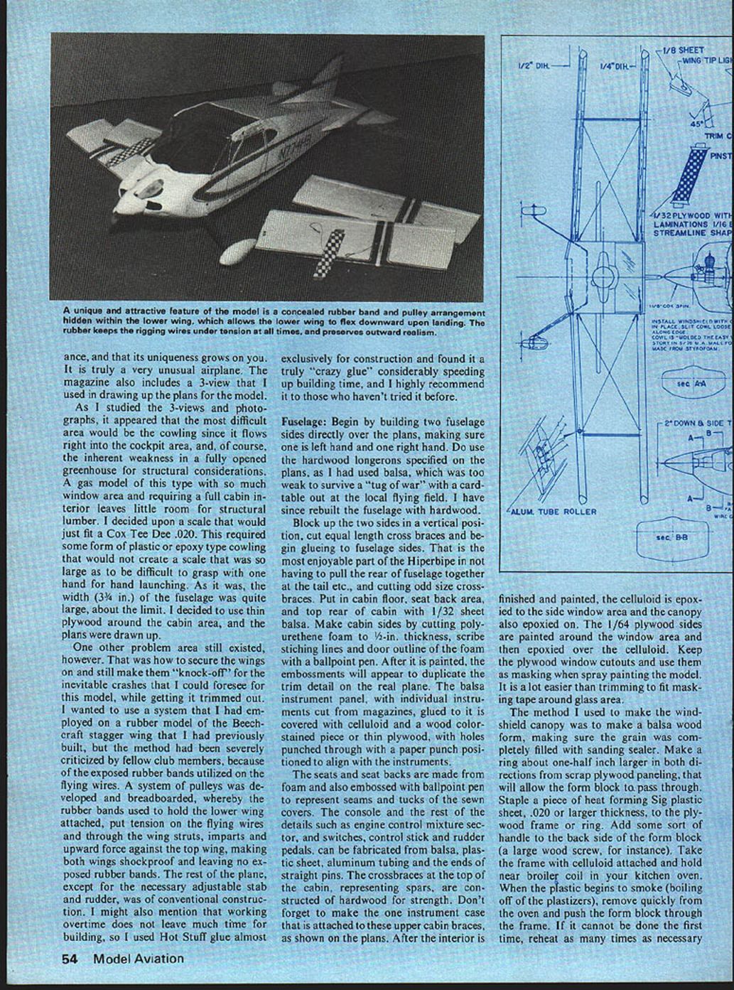
One other problem still existed: how to secure the wings and still make them "knock-off" for the inevitable crashes while getting the model trimmed out. I wanted to use a system I had employed on a rubber model of a Beechcraft stagger wing that I had previously built, but the method had been severely criticized by fellow club members because of the exposed rubber bands used on the flying wires.
A system of pulleys was developed and breadboarded whereby the rubber bands used to hold the lower wing, when attached, put tension on the flying wires and through the wing struts imparted an upward force against the top wing. This made both wings shockproof and left no exposed rubber bands.
The rest of the plane, except for the necessary adjustable stab and rudder, is of conventional construction. Working overtime does not leave much time for building, so I used Hot Stuff glue almost exclusively and found it a real time-saver. I highly recommend it to those who haven't tried it.
Fuselage
Begin by building two fuselage sides directly over the plans, making sure one is left-hand and one right-hand. Do use the hardwood longerons specified on the plans — I had used balsa, which was too weak to survive a tug-of-war with a card table at the local flying field. I have since rebuilt the fuselage with hardwood.
Block up the two sides in a vertical position, cut equal-length crossbraces and begin gluing them to the fuselage sides. That is the most enjoyable part of the Hiperbipe: you do not have to pull the rear of the fuselage together at the tail and cut odd-size crossbraces. Put in the cabin floor, seat-back area, and top rear of cabin with 1/32" sheet balsa.
Make cabin sides by cutting polyurethane foam to 1/4" thickness; scribe stitching lines and the door outline of the foam with a ballpoint pen. After it is painted, the embossments will duplicate the trim detail on the real plane.
The balsa instrument panel, with individual instruments cut from magazines and glued to it, is covered with celluloid and a wood-colored stained piece of thin plywood. Punch holes through the plywood with a paper punch positioned to align with the instruments.
The seats and seat backs are made from foam and embossed with a ballpoint pen to represent seams and tucks of the sewn covers. The console and other details — engine control mixture sector, switches, control stick and rudder pedals — can be fabricated from balsa, plastic sheet, aluminum tubing and the ends of straight pins. The crossbraces at the top of the cabin, representing spars, are constructed of hardwood for strength. Don't forget the small instrument case attached to these upper cabin braces, as shown on the plans.
After the interior is finished and painted, epoxy the celluloid to the side window area and epoxy the canopy on. Paint the 1/64" plywood sides around the window area and then epoxy them over the celluloid. Keep the plywood window cutouts and use them as masks when spray painting the model — it is much easier than trimming masking tape around the glass.
Canopy (windshield) forming
Method to make the windshield canopy:
- Make a balsa wood form and fill the grain completely with sanding sealer.
- Make a plywood ring about 1/2" larger in both directions than the form block to allow the form to pass through.
- Staple a piece of heat-forming Sig plastic sheet (0.020" or larger) to the plywood frame or ring. Add a handle to the back of the form block (a large wood screw works).
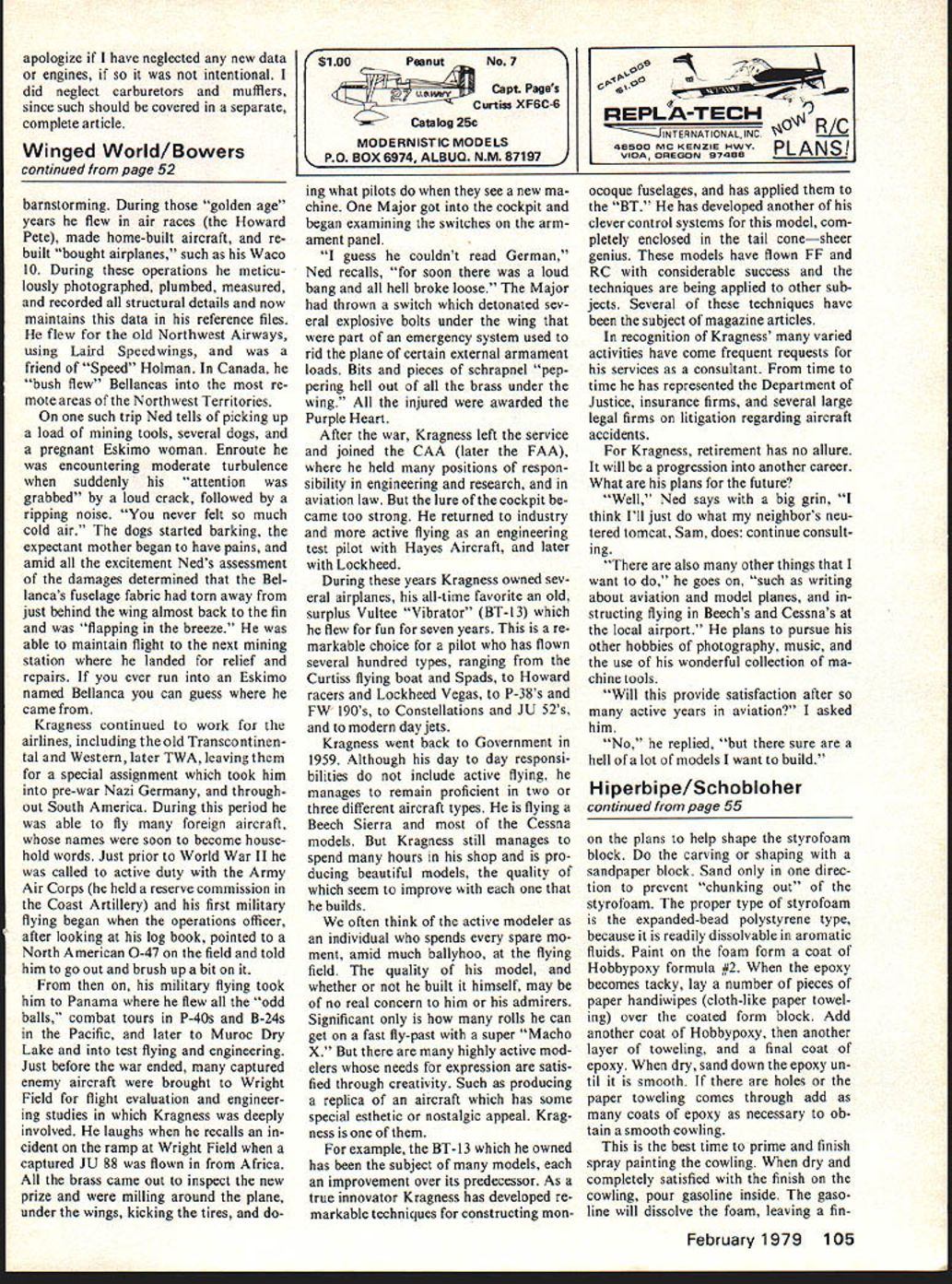
- Take the frame with plastic attached and hold it near the broiler coil in your kitchen oven. When the plastic begins to smoke (boiling off plasticizers), remove it quickly and push the form block through the frame.
- Reheat and repeat as necessary until the form can be pushed into the plastic to the depth required. Be careful not to boil off too much plasticizer — the plastic will turn white and milky.
- Make several canopies and select the best one for the model.
Cowling
The engine cowling is made from a styrofoam block. Three templates are shown on the plans to help shape the styrofoam block. Do the carving or shaping with a sandpaper block. Sand only in one direction to prevent chunking out the styrofoam.
Use expanded-bead polystyrene styrofoam (it dissolves in aromatic fluids). Paint the foam form with Hobbypoxy formula #2. When the epoxy becomes tacky, lay several pieces of paper hand-wipes (cloth-like paper toweling) over the coated foam block. Add another coat of Hobbypoxy, then another layer of toweling and a final coat of epoxy. When dry, sand the epoxy until smooth. If there are holes or the paper comes through, add more coats of epoxy as necessary.
Prime and finish spray-paint the cowling. When dry and you are satisfied with the finish, pour gasoline inside the shell. The gasoline will dissolve the foam, leaving a finished shell.
An alternative, and probably better, method is to coat the foam with an automotive lacquer sealer (very thin lacquer) and lay up layers of cloth with epoxy. That will make a stronger, less brittle shell than the paper/toweling method. The gasoline method is simple and requires little experience but leaves a rather brittle shell.
Reinforce the shell inside with balsa blocks and scrap plywood as required to hold the motor, fuel tank and onboard equipment. Glue the spinner backplate and drill the spinner center hole to fit the shaft. Fit and balance spinner and prop. After installing the motor and firewall, join cowl halves with epoxy fillets, then sand and fill as necessary. Glue the cowl to the fuselage using epoxy and screws. Carve the cockpit area and fit the windscreen. If the windscreen is Plexi, mask and paint it prior to final installation. A finished shell of epoxy paper laminate is an easy way of making a thin cowling and can be redone after a major crack-up (see "Mold It The Easy Way", July 1977, Model Aviation). Trim the cowling to fit around the windshield canopy and attach with small wood screws through the cowling into hardwood blocks cemented to the firewall, recessed for the thickness of the cowling.
Landing gear and radio installation
The Hiperbipe has a conventional landing gear. To increase scale appearance the gear can be faired with balsa or fiberglass fairings. Make axle blocks of hardwood and secure the gear with bolts through the blocks into the fuselage. Install a tailwheel assembly using a laminated plywood mount.
Radio gear installation is straightforward:
- Two servos for ailerons and elevator.
- One servo for rudder if desired.
- A throttle servo.
- An aileron/elevator mixer if using a conventional setup.
Balance the model as shown on the plans and make final adjustments to the center of gravity. Prior to first flight, check control throws and adjust accordingly. Recommended throws at the widest control surface:
- Ailerons: 3/8" to 1/2"
- Elevator: 1/2" to 3/4"
- Rudder: 1/2"
Trim the cowling to fit around the windshield and attach with small screws into hardwood blocks on the firewall.
Wings
The wings are made in a conventional manner, but use the hardwood leading edge specified — it prevents nicks when the model lands in tall dry weeds. The root ribs and the top and bottom areas where struts attach are planked with 1/64" plywood (sold mostly as wing skins for use on foam RC models).
The lower sweptback wings contain the pulley arrangement that allows the wings to flex downward upon landing. The pulley is simply two pieces of telescoping aluminum tubing, one cemented into gussets, the other rotating freely over the first. This pulley arrangement keeps all rubber bands hidden in the wing while still applying tension and keeping flying wires taut.
Wing-tip lights are made from round dowels, tapered and sanded to a streamlined shape. Paint the blunt end red on one tip and green on the other. Mix a small portion of 5-minute Hobbypoxy and lay a drop over the red or green end, just sufficient to cover the entire diameter. Hold the tip light vertical, epoxy edge down; the Hobbypoxy will sag to a streamlined shape and be crystal clear when hardened, forming a clear lens cover.
Cut slots into the plywood for the knock-off wing struts. Use 1/16" hardwood dowels to pin the wings to the fuselage; they should extend only through the fuselage sheet thickness to permit knock-off characteristics.
Tail surfaces
The stabilizer and rudder curved leading-edge pieces are made of water-soaked balsa strips taped to a form until dry. After assembly, sand the laminated leading edges and ribs to a streamlined section.
It is important to make the stab and rudder adjustable on a scale model. My method:
- Use a small No. 2-56 machine screw for the adjustors.
- Sandwich the heads of the screws with a soldered-on washer or nut on both sides of a plywood plate.
- Add an additional nut with a soldered-on wire loop to retain a hardwood dowel that can travel up and down, permitting adjustment of the stab or rudder.
The extreme fuselage width required making two screw adjustors for the stab.
Hinge the stab on two straight pins put through the rear of the fuselage. Cover and completely trim the stab and the three sides of the fuselage before assembling. Push the pins through the fuselage into the stab, then add the dowels at the front through the adjustor screws. After assembly seems correct, complete covering the bottom of the fuselage.
The rudder is similar but pivots on a hardwood dowel that telescopes into a previously attached aluminum tubing in the fuselage. The bracing wires between stab and rudder hold the whole assembly together.
Flying and fuel note
Before attempting to fly the model, one important suggestion: the Cox Tee Dee .020 with its integral gas tank will run almost three minutes on a full tank with a large 5-1/2 x 3 prop. I had it figured that by tipping the plane approximately 120 degrees from horizontal I could put in only about one-third of a tank with a squeeze bulb. However, at the 1976 Nationals I must have eventually filled the tank after two attempts to take off, and consequently had a fly-away and lost the airplane. Two weeks later, through the generous efforts of local model clubs, I retrieved the model.
I now fly with the tank filled two-thirds full and use a rubbery plug made from Selastic (Dow Corning bathtub caulk). It is impervious to fuel and doesn't stick to the tank. It can be removed and carved down to a dimension that permits any engine run you desire. In the heat of a contest it is now impossible to over-fill the tank.
The Cox Tee Dee .020 will run nearly three minutes on a full tank with the recommended prop, so limit fuel and use the Selastic plug method to prevent accidental overfilling in contests.
Results and closing
Despite the fly-away at the Nationals and not qualifying for any landing approach points, the model did win third place and the E.A.A. award for best home-built free flight, gas category. After a later crack-up with a card table at a local contest, the model was rebuilt and took first place at the 1977 Canadian Nationals, demonstrating a smooth take-off and, like any other biplane, a very stable flight pattern.
I hope you will build this model and enjoy flying it as much as I have. I would like to hear from you.
Transcribed from original scans by AI. Minor OCR errors may remain.

