
HL-2 Electric!
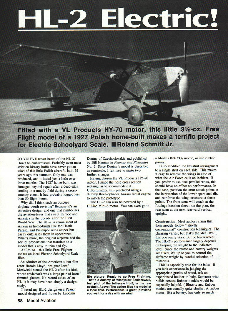
So you've never heard of the HL-2? Don't be embarrassed. Probably even most aviation history buffs have never gotten wind of this little Polish airplane, built 64 years ago this summer. Only one was produced, and it lasted just a little over three months. The 1927 home-built was damaged beyond repair after a dead-stick landing in a muddy field during a cross-country event. It had probably logged less than 50 flight hours.
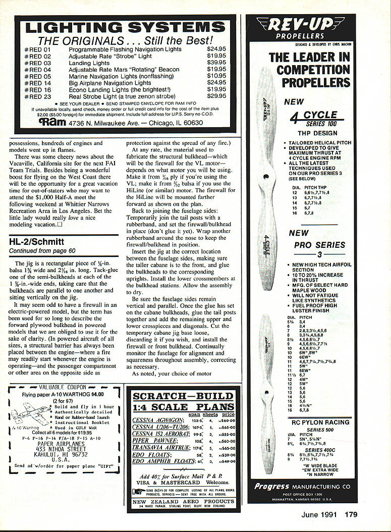
Why revive such an obscure airplane? Because it's an attractive design and symbolizes the aviation fever that swept Europe and America in the decade after the First World War. The HL-2 is reminiscent of American home-builts like the Heath Parasol and Pietenpol Air-Camper but easily outclasses them in appearance. What's more, the original airplane had proportions that translate to a model that's easy to trim and fly.
At 3-1/2 oz., this little Free Flighter makes an ideal Electric Schoolyard Scale flier.
An admirer of American silent film actor Harold Lloyd, designer Jozef Medwicki named the HL-2 after his idol, whose trademark was a large pair of horn-rimmed glasses. No record exists of an HL-1; it may have been simply a design study.
I based my HL-2 design on a Peanut model designed and flown by Lubomir Koutny of Czechoslovakia and published by Bill Hannan in Peanuts and Pistachios No. 5. Since Koutny's model is described as semiscale, I felt free to make two further changes: (1) chosen the VL Products HY-70 motor and made the nose cross section rectangular to accommodate it (which precluded a dummy three-cylinder Anzani radial), and (2) modified the lift-strut arrangement to a single strut on each side to make wing removal easier after an incident. The HL-2 can also be powered by a HiLine Mini-6 motor, a Modela .024 CO2 motor, or by rubber power.
Construction
Most authors claim that their models follow "strictly conventional" construction techniques. Well, this one really does. But be forewarned: the HL-2's performance largely depends on keeping the weight to the indicated level. Since motor and battery weights are fixed, control the airframe weight by careful selection of materials—especially balsa. If you lack experience judging wood grades, ask an experienced builder for help.
Materials (recommended)
- Template: 1/64 in. phenolic sheet (Formica veneer) or thin sheet metal
- Plywood where specified: 1/16 in. or 1/8 in.
- Rib stock options: 3/32 in., 1/16 in., or 1/8 in. quarter-grain balsa (6–8 lb/cu ft for ribs; use firmer grades for leading edges and spars)
- Leading edge: 1/8 x 3/16 in. strip, firm balsa (10–12 lb/cu ft)
- Trailing edge: 3/32 x 1/8 in. medium balsa (8–10 lb/cu ft)
- Spars: lower spars 1/16 x 1/16 in. firm balsa; top spar 1/16 in. firm A-grade stock
- Sheet: 1/32 in. medium balsa for sheeting
- Struts: 3/32 x 3/16 in. hard balsa (for lift struts)
- Wire: .032 in. music wire for cabane parts; 1/16 in. music wire for tailwheel
- Tubing: 3/32 in. I.D. aluminum tubing for gear and 1/16 in. aluminum tubing for strut attach points
- Glue: CyA (CA), white glue where specified
- Covering: silkspan (lightweight), Micafilm or MonoKote (if heavier covering acceptable)
- Dope: Lite-Coat (recommended) thinners as indicated
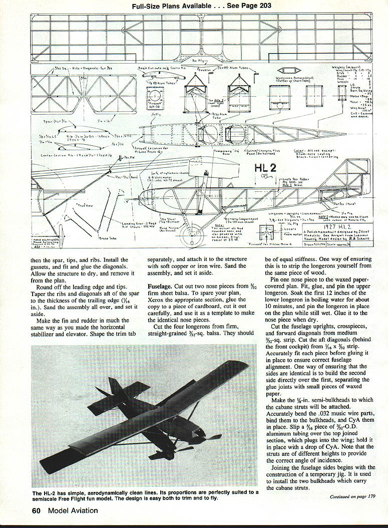
(Refer to the plan for exact part locations and dimensions.)
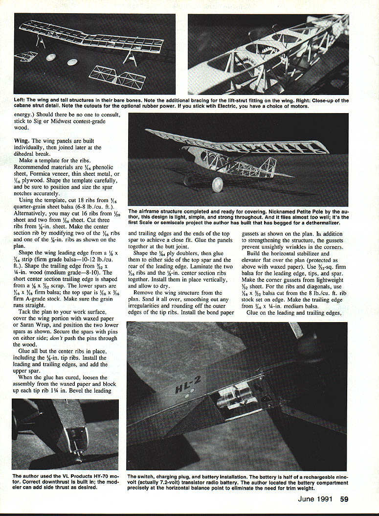
Wing
Wing panels are built individually and joined later at the dihedral break. Make template ribs from the phenolic or thin metal template and be sure spar-notch positions and sizes are accurate.
Rib options (follow the plan for the chosen thickness):
- Cut 18 ribs from 3/32 in. quarter-grain balsa (6–8 lb/cu ft), or
- Cut 18 ribs from 1/16 in. quarter-grain sheet balsa, or
- Cut 16 ribs from 1/8 in. sheet and two from 3/32 in.; some ribs (tip and center-section) may be 1/8 in. as shown on the plan.
Build steps:
- Shape the leading edge from 1/8 x 3/16 in. firm balsa. Shape the trailing edge from 3/32 x 1/8 in. medium balsa. Short center-section trailing edge may be from 1/8 x 3/32 in. scrap.
- Position two lower spars on the plan over waxed paper or Saran Wrap, and secure with pins (do not pierce wood).
- Glue center ribs in place, including tip ribs. Install leading and trailing edges and add the upper spar.
- When the glue cures, loosen from waxed paper and block up tip rib 1/4 in. Bevel ends at the top spar for a close fit.
- Glue panels together with a butt joint at the center dihedral.
- Glue 1/64 in. ply doublers to either side of the top spar at the rear leading edge. Laminate two 1/16 in. ribs for the center-section ribs and install them vertically.
- Remove wing from plan, sand smooth, round tip ribs, and install bond-paper gussets to strengthen corners and prevent wrinkles.
- When covering, do the lower surface first, position and CA the lift-strut eye fittings, then cover the upper surface.
- While the covering is still wet, pin wing panels to create washout: weight down the tip leading edge on a 1/4 in. block and raise the tip trailing edge an additional 3/16 in. at the dihedral toes.
Horizontal Stabilizer, Elevator, Fin and Rudder
Build the horizontal stabilizer and elevator flat over the plan (use waxed paper protection). Recommended parts:
- Leading edge, tips, and spar: 3/32 in. firm balsa
- Ribs and diagonals: 3/16 x 3/32 in. balsa cut from 8 lb/cu ft rib stock on edge
- Trailing edge: 1/16 x 1/4 in. medium balsa
- Corner gussets: lightweight 1/32 in. sheet
Steps:
- Glue leading and trailing edges, then spar, tips, and ribs. Install gussets and diagonals.
- Round off leading edges and tips; taper ribs and diagonals aft of the spar to the thickness of the trailing edge (1/16 in.).
- Make fin and rudder similarly. Shape the trim tab separately and hinge it with soft copper or iron wire.
- Sand and set aside.
Fuselage
- Cut two nose pieces from 3/32 in. firm sheet balsa (use a cardboard template made from a Xerox of the plan to spare the original).
- Cut four longerons from firm, straight-grained 3/32 in. square balsa; insure equal stiffness (strip from same piece of wood if possible).
- Pin one nose piece to the plan (covered with waxed paper), fit, glue, and pin the upper longeron. Soak the first 12 in. of the lower longeron in boiling water for about 10 minutes to bend into place; pin and glue when dry.
- Cut fuselage uprights, crosspieces, and forward diagonals from medium 3/32 in. sq. strip. Cut aft diagonals (behind forward cockpit) from 1/8 x 3/32 in. strip. Accurately fit each piece before gluing to ensure correct alignment.
- Build the second fuselage side over the first, separating glue joints with small pieces of waxed paper for identical sides.
Cabane bulkheads and motor firewall:
- Make 1/16 in. semi-bulkheads for cabane strut attachment. Bend .032 in. music wire cabane parts accurately, bind to the bulkheads and CA in place. Slip a 1/16 in. piece of 3/32 in. O.D. aluminum tubing over the top joined section which plugs into the wing; secure with a drop of CA.
- The firewall material and location depend on motor used:
- If using the VL Products HY-70 motor: make firewall from 1/16 in. plywood and position as shown on the plan. The HY-70 was mounted to the firewall with four 2-56 x 1/2 in. screws and blind nuts.
- If using the HiLine Mini-6 (or similar), make the firewall from 3/32 in. balsa and mount it 1/16 in. farther forward (detail shown on plan).
- Prior to installing the motor, glue 1/16 in.-sq. mounting strips to the inner surfaces of the nose pieces at the location and angle shown on the plan (4° downthrust). Ensure the mounting strips are parallel—use a template for accuracy.
Joining fuselage sides:
- Construct a temporary jig: rectangular piece of 1/2 in. balsa, 1-1/2 in. wide and 2-1/2 in. long. Tack-glue a semi-bulkhead at each 1-in.-wide end, ensuring they are parallel and vertical.
- Temporarily join tail posts with a rubber band, set firewall/bulkhead in place (don’t glue yet), and wrap another rubber band around the nose to hold position.
- Insert jig between fuselage sides with taller cabane to the front. Glue the bulkheads to corresponding uprights and install lower crossmembers at bulkhead stations.
- When dry, glue tail posts together, add remaining upper and lower crosspieces and diagonals. Remove temporary jig base and install firewall or front bulkhead.
- Continuously check alignment and squareness throughout assembly.
Fit lift-strut attach points as 1/2 in. long pieces of 1/16 in. aluminum tubing bound with thread to the lower longerons and CA'd in place. Add 3/32 in. gussets.
Sheeting:
- Sheet the top of the fuselage from the firewall to aft of the rear cockpit with 1/32 in. medium sheet, grain crosswise.
- Trace and cut cockpit openings from the plan.
- Plank the lower surface of the nose with 1/32 in. sheet, extending back to the crossmember at the forward landing gear fitting. If using the VL motor, glue the forward edge of the 1/32 in. sheet to the firewall. If using the HiLine motor, install a 1/8 x 1/8 in. crossmember just aft of the rear of the motor and begin covering at that motor.
- Carefully sand the completed structure and set aside.
Landing Gear and Wheels
Landing gear struts:
- Each main gear leg is formed from two pieces of bent music wire: a forward strut and a rear strut. Make two forward and two rear pieces (see plan).
- Join a front and rear piece with a short piece of annealed 3/32 in. I.D. brass tubing (about 3/8 in. long). Anneal the tubing by heating until it changes color, quenching in water, then flattening the midsection slightly with pliers.
- Insert straight ends of the wire pieces into opposite ends of the tubing; bend tubing to achieve the correct V shape. Fit upper ends into brass-tube fittings in the fuselage. Make minor adjustments for alignment; when satisfied, secure the wire/tube joints with a drop of CA (ensure tubing is clean).
- Make a left-hand and right-hand strut.
Wheels:
- Laminate wheels from two disks of 1/8 in. thick medium balsa, cut slightly oversize. Add two small 3/16 in. dia. 1/32 in. plywood disks on each side.
- Drill hub hole (1/16 in.), insert a 2-56 screw, place nut and sand to shape with wheel mounted on the screw mandrel (Dremel or hand drill works).
- Insert 1/2 in. long piece of 3/32 in. I.D. aluminum tubing through the hub, protruding slightly on one side, and secure with CA.
- Fit a shallow bond-paper cone over the other side and cement.
- Balance wheels and check stance.
Fit lift-struts: cut 6-1/2 in. lift-struts from 3/32 x 3/16 in. hard balsa and sand to an oval cross section. Bend upper and lower fittings from 1/32 in. music wire: the upper is a hook to engage an eye on the wing; the lower is an L that sits in the fuselage tube. Bind fittings to strut with thread, secure with CA.
Tailwheel: 1/16 in. music-wire hairpin held in the fuselage by a plywood plate as shown on the plan.
Covering and Finishing
Covering choices weigh heavily on performance:
- Lightest: Japanese tissue (good aero strength, poor puncture resistance).
- Silkspan: stronger than tissue, commonly used on rubber models.
- Micafilm or light MonoKote: 25–50% heavier than doped silkspan but considerably stronger.
The author used colored silkspan (red) pre-doped for scale color without excessive weight.
Covering and doping:
- Predope the structure if using silkspan. Position the silkspan, reactivate the dope with thinner, and press material down, smoothing out wrinkles. Keep covering pieces just slightly larger than the structure segments.
- Shrink the covering by spraying rubbing alcohol with an atomizer. Pin tail surfaces to a flat form while shrinking to prevent warpage.
- For the wing, spray one side at a time, pin the center, and maintain dihedral washout while wet (block up tip leading edge and raise tip trailing edge).
- After shrinking, apply two coats of Lite-Coat thinned 50:50. To prevent warpage, do one side at a time, pinning the untreated side.
- Apply a third coat of dope to the fuselage because of extra handling.
- Fair cabane and landing struts by wrapping 1/2 in. wide balsa paper around the strut and a 1/2 x 7/32 in. balsa strip, cementing and rounding off the trailing edge. Dope struts with two coats clear followed by two coats of Sig Fokker Red. Doped wheels and lift struts may be red, use flat black paint to simulate tires.
Do not cover the bottom of the fuselage initially—this allows building the battery compartment at the balance point without added trimming weight (see Balancing).
Initial Assembly
- Remove tissue covering from recesses in the bottom of the 1/4 in. center rib.
- Place the wing upside down and block it stationary. Cut two pieces of 3/32 in. I.D. aluminum tubing (1/8 in. O.D.) and slip them over the cabane strut 3/32 tubing.
- Turn the fuselage upside down on its cabane struts and fit the 1/4 in. tubing into the recesses in the center rib. Tack each tube with a drop of CA.
- When glue hardens, draw the fuselage forward leaving the 1/4 in. tubing in the wing aligned with the cabanes. Permanently CA the wing tubing in place.
- Check lift-strut fit between wing and fuselage; they should be snug but not tight and must not distort the wing.
- With wing fixed, cut the horizontal-stabilizer slot slightly larger in front than rear to allow angle-of-incidence adjustment with leading-edge shims. Cement stabilizer in place at the spar only. Ensure fin/rudder alignment with fuselage centerline before gluing. Add the tail skid. Do not install stabilizer struts until after flight testing and trimming.
- Insert landing gear struts into fuselage tubing but don't glue. Cut 5/8 in. length of .032 in. music wire for axle, bind it to landing gear struts leaving 5/16 in. on each side for wheels, and CA in place. Install washer and wheels, secure with a 1/16 in. piece of 1/32 in. I.D. aluminum tubing and one drop of CA.
- Finally, install motor and propeller.
Balancing
- Support the airplane on the wing lift-strut fittings. Place battery on the fuselage top and slide it forward or aft until the craft balances horizontally.
- Build the battery compartment precisely at this balance point in the underside of the fuselage (we left the bottom uncovered for this reason). Add crossmembers and structure as necessary.
- Mount the switch close to the charging-jack panel and install wiring per motor instructions.
- Cover and dope the fuselage bottom after battery compartment and wiring are finalized.
Markings and Trim
- Photographs and data indicate the original HL-2 was all red except for a natural aluminum nose cowl.
- The fuselage sides carried HL-2 lettering and a sketch of Harold Lloyd's horn-rimmed glasses in black.
- No registration numbers shown.
- Simulate cockpit padding with a strip of split black tubing CA'd around the cockpit edge. The author formed this from stripped 12-gauge automotive wire insulation slit with an X-Acto blade. Add windshields as shown on the plan.
Flying
- Choose a calm day. Check balance again—it should balance at or immediately (1/16 to 1/8 in.) aft of the main (upper wing).
- Remove propeller and test-glide the model over tall grass. Adjust stabilizer shims until glide is satisfactory.
- Reinstall prop and attempt a powered flight on no more than a quarter charge. Increase power runs gradually and add right or left thrust as required.
- Typical starting trim: about 1° right thrust and rudder tab bent ~1/32 in. to the left produced a prototype that climbed and glided in a large left circle.
- If the model porpoises, move the battery slightly aft. If it has a strong tendency to turn, check rudder alignment and motor thrust angles and correct them.
Performance notes:
- The HL-2 is an excellent flier and surprisingly lively in thermals. The little 3-1/2 oz. ship flew eight to ten minutes on only one-third charge in thermals, requiring a long chase. The author never charged beyond 40% capacity. Normal (non-thermal) durations ranged 1:45 to 2:15.
- This is the first scale or semiscale model the author built that begs for a dethermalizer.
Acknowledgments
Thanks to James R. Smith for reviewing construction sequences and making helpful suggestions.
References
- Cynk, Jerzy B. Polish Aircraft 1893–1939.
- Hannan, Bill. International Peanuts & Pistachios, vol. 5.
Transcribed from original scans by AI. Minor OCR errors may remain.

