
Honcho
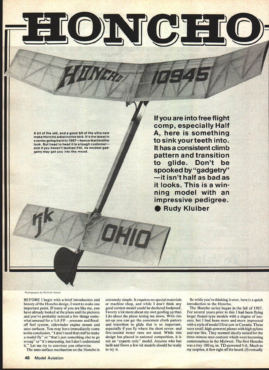
A bit of the old and a good bit of the ultra-new make Honcho a distinctive bird. It's the latest in a series going back to 1967 — hence that familiar look. Head to head it is a tough customer, and if you haven't tackled FAI, its modest gadgetry may get you into the mood.
If you are into free-flight competition, especially Half A, here is something to sink your teeth into. It has a consistent climb pattern and a smooth transition to glide. Don't be spooked by "gadgetry" — it isn't half as bad as it looks. This is a winning model with an impressive pedigree.
- Rudy Kluiber
Before I begin with a brief introduction and history of the Honcho design, I want to make one important point. If many of you are like me, you have already looked at the plans and the pictures and you've probably noticed a few things somewhat unusual for a 1/2A FF — pressure and flood-off fuel system, sidewinder engine mount and auto surfaces. You may have immediately come to the conclusion, "I don't need that stuff to make a model fly," or "that's just something else to go wrong," or "it's interesting, but I don't understand it." Let me try to convince you otherwise.
The auto-surface mechanism on the Honcho is extremely simple. It requires no special materials or machine shop, and while I don't think any good contest model could be declared foolproof, I worry a lot more about my own goofing up than I do about the plane letting me down. With this setup you can get the consistent climb pattern and transition to glide that is so important, especially if you fly where the short seven- and five-second motor runs are used. While this design has placed in national competition, it is not an "experts only" model. Anyone who has built and flown a few kit models should be ready to try it.
A short introduction and history of the Honcho
The Honcho series began in the fall of 1967. For several years prior to this I had been flying larger floater-type models with a degree of success, but I had become more impressed with a style of model I first saw in Canada. These were small, high-powered planes with high pylons and rear fins. They seemed ideally suited for the three-minute-max contests which were becoming commonplace in the Midwest. The first Honcho was a tiny 180 sq. in., TD-powered 1/2A. Much to my surprise, it flew right off the board. It proved too small for the consistency needed for successful contest flying. A 400 sq. in., TD-15-powered ship was scaled up from the 1/2A and this model placed second at the 1969 Nats in Philadelphia.
Since then the Honcho has been built in many sizes and classes from .02 payload to Class C, and has continued to do well — including a first in B and several other places in 1/2A and A at various Nats. As recently as the 1978 Nats in Lake Charles, LA, Honchos placed third in A. Auto surfaces were added to the ships starting in 1970. Once again, I can thank my Canadian friends for the original auto-surface arrangement, although I have made some modifications. Likewise, the Honcho design has been changed here and there over the years, although the basic layout remains much the same.
Recommended engine/timer setup
The use of this particular engine/auto-surface setup requires a TD .049 with a Kustom Kraft needle valve assembly, pressurized backplate and, preferably, an enlarged venturi. These items may be available through local hobby shops or you can obtain them from Joe Klause at Kustom Kraftsmanship. You may also want to look into his line of completely reworked TD engines which I have used for some time. This may set you back a few dollars, but it is a worthwhile investment, as your engine will be easier to tune and stands to gain some power as well.
Construction
Wing and Stab
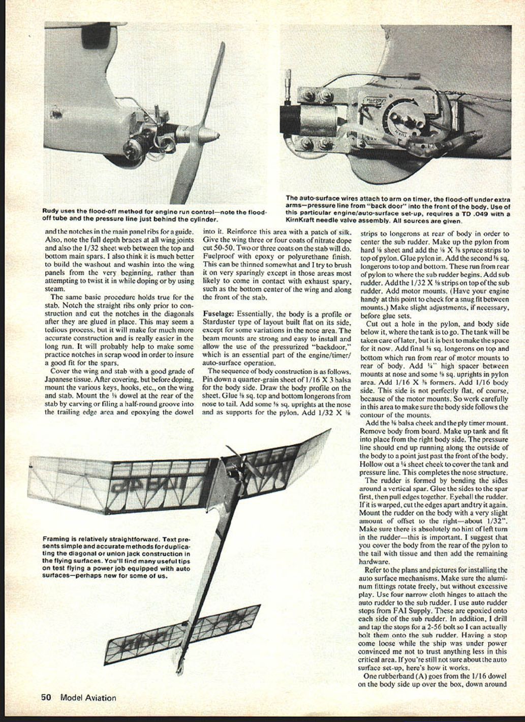
These are relatively straightforward in structure and should not present any problems. There are, however, a few particulars I would like to cover, especially for those who may not have built a wing or stab using diagonal or union-jack type construction.
With regard to the wing:
- Make spar notches only in the ribs for the main panels prior to construction.
- Glue all the diagonal ribs and the tip ribs in without notches. Then cut the notches one at a time with a razor and straightedge, using the plan and the notches in the main panel ribs for a guide.
- Note the full-depth braces at all wing joints and the 1/32" sheet web between the top and bottom main spars.
- It is better to build the washout and wash-in into the wing panels from the very beginning, rather than attempting to twist it in while doping or by using steam.
The same basic procedure holds true for the stab:
- Notch the straight ribs only prior to construction and cut the notches in the diagonals after they are glued in place.
- This may seem tedious, but it makes for much more accurate construction and is easier in the long run. Make some practice notches in scrap wood to ensure a good fit for the spars.
Cover the wing and stab with a good grade of Japanese tissue. After covering, but before doping, mount the various wires, hooks, etc., on the wing and stab. Mount the 1/8" dowel at the rear of the stab by carving or filing a half-round groove into the trailing edge area and epoxying the dowel into it. Reinforce this area with a patch of silk.
Finish:
- Give the wing three or four coats of nitrate dope cut 50-50. Two or three coats on the stab will do.
- Fuelproof with epoxy or a polyurethane finish. Thin somewhat and brush on sparingly except in areas likely to come in contact with exhaust spray (bottom center of the wing and along the front of the stab).
Fuselage
Essentially, the body is a profile or Starduster type layout built flat on its side, except for some variations in the nose area. The beam mounts are strong and easy to install and allow the use of the pressurized "backdoor," which is an essential part of the engine/timer/auto-surface operation.
Sequence of body construction:
- Pin down a quarter-grain sheet of 1/16" x 3" balsa for the body side. Draw the body profile on the sheet.
- Glue 1/8" sq. top and bottom longerons from nose to tail.
- Add some 1/8" sq. uprights at the nose and as supports for the pylon.
- Add 1/32" x 1/8" strips to longerons at rear of body to center the sub rudder.
- Make up the pylon from hard 1/8" sheet and add 1/8" x 1/2" spruce strips to top of the pylon. Glue pylon in.
- Add the second 1/8" sq. longerons to top and bottom. These run from rear of pylon to where the sub rudder begins.
- Add sub rudder. Add 1/32" x 1/2" strips on top of the sub rudder.
- Add motor mounts. (Have your engine handy to check for a snug fit between mounts. Make slight adjustments if necessary before glue sets.)
- Cut out a hole in the pylon and body side below it where the tank is to go. Fit tank later; make space now.
- Add final 1/8" sq. longerons on top and bottom which run from rear of motor mounts to rear of body.
- Add a 1/8" high spacer between motor mounts and nose and some 1/8" sq. uprights in the pylon area.
- Add 1/16" x 1/8" formers and the 1/16" body side. This side must follow the contour of the motor mounts, so work carefully.
- Add the 1/8" balsa cheek and the ply timer mount. Remove body from the board.
- Make up the tank and fit into place from the right body side. The pressure line should run along the outside of the body to a point just past the front of the body. Hollow out a 1/4" sheet cheek to cover the tank and pressure line. This completes the nose structure.
Rudder:
- The rudder is formed by bending the sides around a vertical spar. Glue the ribs to the spar first, then pull edges together.
- If warped, cut the edges apart and try again.
- Mount the rudder on the body with a very slight offset to the right — about 1/32". Make sure there is absolutely no hint of left turn in the rudder — this is important.
Cover the body from the rear of the pylon to the tail with tissue and then add the remaining hardware.
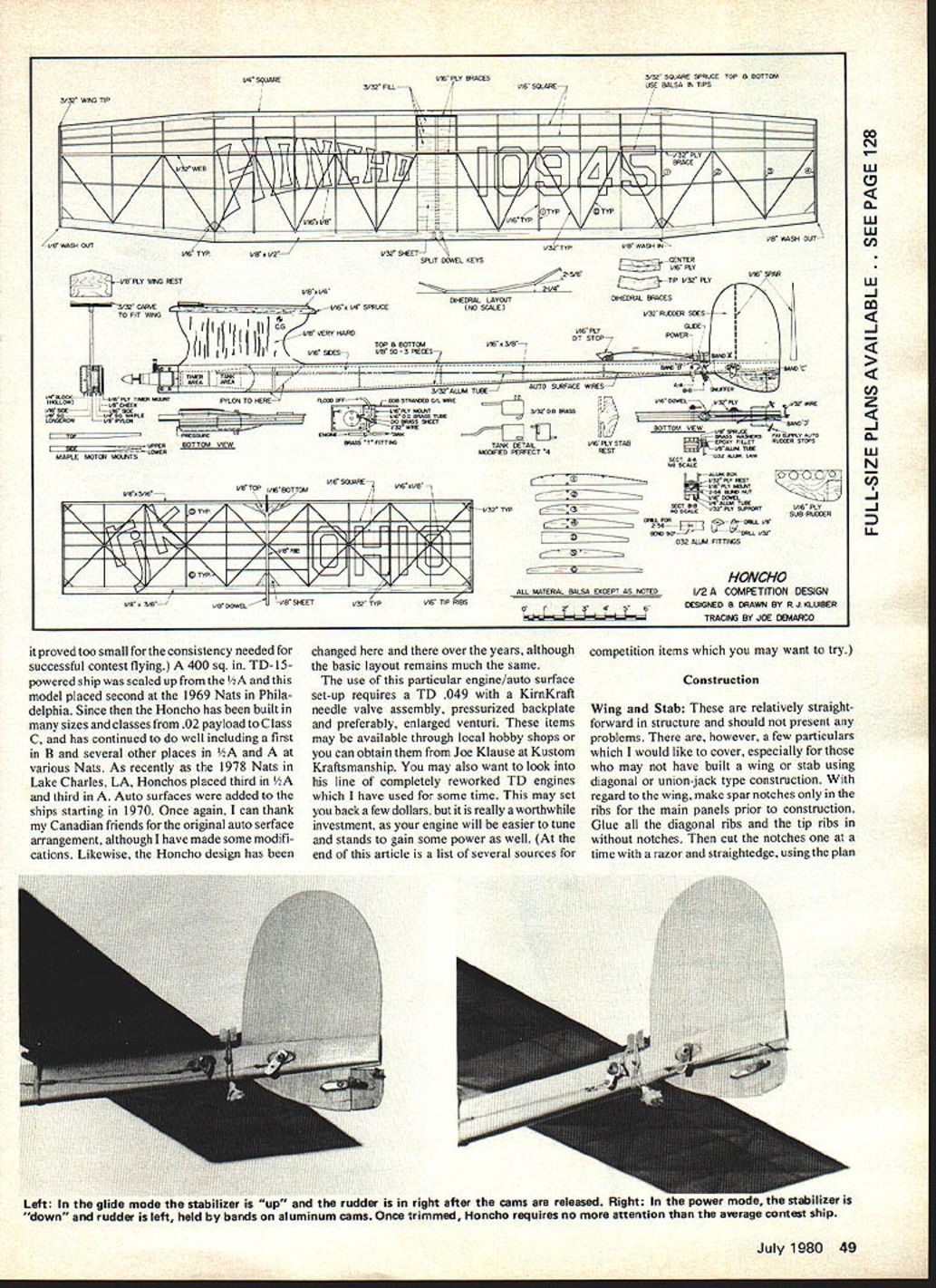
Installing the auto-surface mechanisms
- Refer to the plans and pictures for details. Make sure the aluminum fittings rotate freely, but without excessive play.
- Use four narrow cloth hinges to attach the auto rudder to the sub rudder. I use auto-rudder stops from FAI Supply. These are epoxied onto each side of the sub rudder. In addition, I drill and tap the stops for a 2-56 screw so I can bolt them onto the sub rudder. Having a stop come loose while the ship was under power convinced me not to trust anything less in this critical area.
How the auto-surface system works
- One rubber band (A) goes from the 1/16" dowel on the body side up over the box, down around the fuse and back up to the dowel.
- A second band (B) goes from the dowel down around the bottom of the body, up and over the 1/8" dowel on the rear of the stab and around the aluminum cam mounted on the body side. When the auto line to the timer is engaged, this cam maintains tension on band (B), holding the stab down in the power setting. When the auto line is released, band (B) is released, allowing the stab to kick up until the 1/8" dowel comes into contact with band (A) stretched across the top of the box. This is the glide setting.
- When the DT fuse burns through band (A) the stab pops up all the way to DT position.
- In like manner, band (C), running from the second aluminum fitting to the wire horn, holds the auto rudder in the power setting. When band (C) is released, the auto rudder is pulled into the glide setting by band (D).
- The timer is a Tatone flood-off, mounted upside down with an additional arm mounted next to it. The extra arm holds down the flood-off tubing. The auto-surface wires engage the arm on the timer itself.
Finish the front end with sealer and two or three coats of epoxy or polyurethane. The last item should be the auto lines. Make these from .008" stranded control line. Loop the wires through the aluminum fittings, wrap with copper wire and solder. Then run the wires through the tube guides to the nose. Form loops at the other end to fit over the timer arm.
Some purists may prefer running the auto lines inside the body; having them on the outside makes for easier installation, troubleshooting and replacement. Besides, when the model is several hundred feet up you can't even see those wires.
When the lines are engaged on the timer arm, the aluminum fittings should be in the position indicated on the plans. Bend a flood-off tube from 1/16" brass. Solder a brass tab to the tube so it can be bolted onto the engine. Also solder a short 1/8" length of 1/16" I.D. brass tubing onto the rear end of the flood-off tube to provide a tight fit for the surgical tubing coming from the tank. The pressure line is a short length of tubing running from the pressure fitting on the rear crankcase cover of the engine to the tubing from the tank which extends just past the front of the body.
Trimming
Now that you have your new little gem all done, it's time to thoroughly check out your engine/timer/auto-surface setup. This is partly to become comfortable with the setup and to make sure it works properly. If this is your first experience with auto surfaces, it may seem as if there are an awful lot of rubber bands, arms, cams, etc., to take care of. Don't let it throw you. That's a normal reaction and once you get into it the whole operation will become quite automatic.
Check everything with the engine running. The flood-off release should occur about a half second before the auto-surface release. This can be adjusted by bending the extra arm over the flood-off line closer to or farther away from the timer arm.
Pick a calm morning or evening. Begin with auto surfaces in the glide setting, and adjust for a steady right-hand glide using auto rudder and some stab tilt. My ship's current settings are 3/16" right stab tilt and 5/16" right rudder.
Note: 1/16" negative stab incidence (as a model datum).
Power-gliding: a safe method for first power flights
The first power flight with an auto-surface model can be hairy. I developed a trimming method to make those initial flights relatively safe: power gliding.
- Set the auto surfaces to the power settings (my actual power settings are 1/16" left rudder and zero stab incidence).
- Pick a spot on the ground about 40 feet in front and glide the model at that spot with a good firm launch — much harder than an ordinary test glide. Keep the nose slightly below horizontal as you release.
- The model should fly straight for 20–30 feet then the nose should slowly come up and over to the right as the ship slows down. There should be no left bank tendency and no abrupt stall.
- Adjust auto rudder and stab incidence to achieve this reaction. Repeat the power-glide test until you get the desired behavior. It may require 15–20 glides; be certain there is no breeze during testing.
Once the power glide looks good, the model is ready to be flown.
Power flights
- Begin with about a two-second full-power engine run.
- Always launch in a near-vertical position, slightly to the right of the wind.
- The model should climb straight away leaning slightly to the right.
- Don't worry too much about the transition to the glide until you have increased the engine run to about five seconds. If the model heels over sharply into a semi-wingover when the motor cuts, the auto surfaces are coming in too quickly after flood-off. If the model stalls, there is too long a delay after flood-off before the auto surfaces move.
- Adjust the spacing of the two arms on the timer accordingly to get the proper transition.
You should be able to adjust the power pattern on the Honcho to groove with almost any suggestion. Do turn in some centering once the power is about right. One last suggestion: on every flight as you are ready to release the model, look down at the stab and auto rudder to be sure they are set properly — leave the snap rolls to the Pitts Specials.
Once trimmed, this model won't require any more attention than the average contest ship. I hope you will be pleased with its performance.
If anyone wishes to contact me concerning the article, my address is: Rudy Kluiber 2021 Lakeland Ave. Lakewood, OH 44107
Sources for engines and props
- Kustom Kraftsmanship
Box 2699 Laguna Hills, CA 92653 (Engines and engine rework)
- J L Machine Service
5847 N. 67th St. Milwaukee, WI 53218 (Engine rework)
- K & W Enterprises
7824 Lexington Ave. Philadelphia, PA 19152 (Fiberglass props)
Transcribed from original scans by AI. Minor OCR errors may remain.

