
HOOPTEE MK III
- an update on c/l rat racing
RAT RACING has evolved from a good beginner's event to probably the most competitive control-line event in its 20 some years of existence. In the old days any form of aircraft was acceptable as long as it would take off and land. The winner was usually the one who could successfully restart the engine a couple of times in the race.
Many things have changed in recent years. The state-of-the-art has been upgraded both through technological improvements in the engines and also in the flying techniques. Many of these improvements have proven to be the demise of the event. Participation, especially by new people, is practically non-existent.
I feel the lack of participation or new blood is directly attributable to two areas: the lack of available information and the lack of pilots. It is the intent of this article to make available to the potential newcomer the details on how, where, and why to get started in the event.
The Hooptee MK III model presented in this article is typical of most modern rat racers. It represents the third basic design change I have made in my rat racer designs in the past 12 years. I have been using this design for three years. It has been such a consistent performer, that other top competitors in the Midwest area are now using it also. These include Bill Allen, John Ballard, Gary Fentress, Bob Finley, and Pat Flinn. It is quite easy to construct once you have gone through the exercise a time or two. The first time through may scare you a bit due to the unusual construction technique, namely the fiberglass top, but the future models will become quite easy as your confidence improves.
John F. Kilsdonk
The first step is to select an engine. As of this writing, the HP-40 RRV engine is the most popular. However enough work is being put into the OS-40SR that some day it should at least rank equal or better than the HP. Other 40-size engines are available, however none passes both of the qualities absolutely necessary for a good rat engine: high performance and fast restart capability.
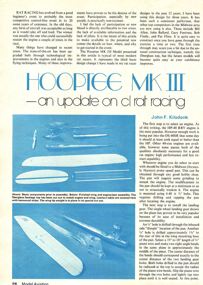
Whatever engine you do select to start with should be fitted to a Midwest (formerly Harters) proto speed pan. This can be obtained through any good hobby shop. The pan will require some grinding to mount the engine. The modifications to the pan should be kept at a minimum so as not to structurally weaken it. The engine is mounted using 4-40 x 5/8" bolts. This requires drilling and tapping the pan after locating the engine.
The next step is to install the landing gear. The single wheel landing gear shown on the plans has proven to be very popular because of its ease of installation and extreme durability.
An 1/8" hole is drilled through the inboard side "dimple" location of the pan. Another 1/8" hole is drilled approximately 1 3/4" to the rear of this in the wing mounting boss of the pan. Select a 15" to 18" length of 1/8" piano wire and make two right-angle bends in the same plane in approximately the middle of the piece. The center distance of the bends should correspond exactly to the center distance of the two landing gear holes. Both holes drilled in the pan should be radiused at the top to accept the radius of the piano wire bends. Slip the piano wire through the two holes and lightly tap into place until it is well seated.
At this point take the rearward wire bend and bend it forward as close to the pan as possible. Make another bend parallel and right against the back of the front wire. Take a length of brass tubing and gently flatten the I.D. cross-section in a vise. Slip it over the two pieces of piano wire and lightly tap into position. Mark the rear wire at the bottom edge of the brass tubing. Remove the tubing and cut off the rear wire at the mark. Reinstall the tubing and bend the whole assembly forward. The wheel axle will be approximately 2 inches forward of the front wire exit from the pan.
Bend forward the 1/8" piano wire on the inboard side 90° to be parallel with the future wing centerline. Install 1/8" Dons wheel, soldering a No. 4 flat washer on both sides. Trim off excess wire and use wheel collars to hold the wheel (tends to vibrate loose).
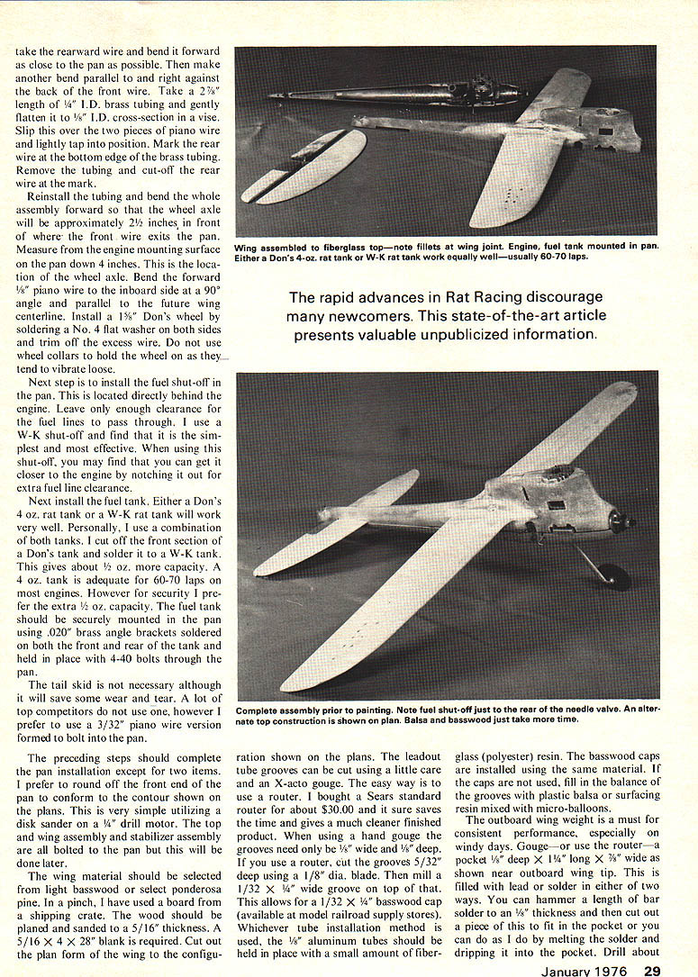
Next, install the fuel shut-off on the pan located directly behind the engine. Leave enough clearance for the fuel lines to pass through. I use the W-K shut-off and find it the simplest and most effective. Using this shut-off you may find you can get closer to the engine by notching out the extra fuel line clearance.
Next install the fuel tank. Either Don's 4-oz rat tank or the W-K rat tank will work very well. Personally I use a combination of both tanks — cut off the front section of the Don's tank and solder to the W-K tank — which gives about a 4-oz capacity. A 4-oz tank is adequate for 60–70 lap runs on these engines. However, for security, I prefer extra capacity. The fuel tank should be securely mounted to the pan using .020 brass angle brackets soldered to both front and rear. The tank is held in place by 4-40 bolts through the pan. The tail skid is not necessary although it will save some wear and tear. A lot of top competitors do not use one, however I prefer to use a 3/32" piano wire version formed to bolt into the pan.
The preceding steps should complete the pan installation except for two items. I prefer to round off the front end of the pan to conform to the contour shown on the plans. This is very simple utilizing a disk sander on a 1/4" drill motor. The top and wing assembly and stabilizer assembly are all bolted to the pan but this will be done later.
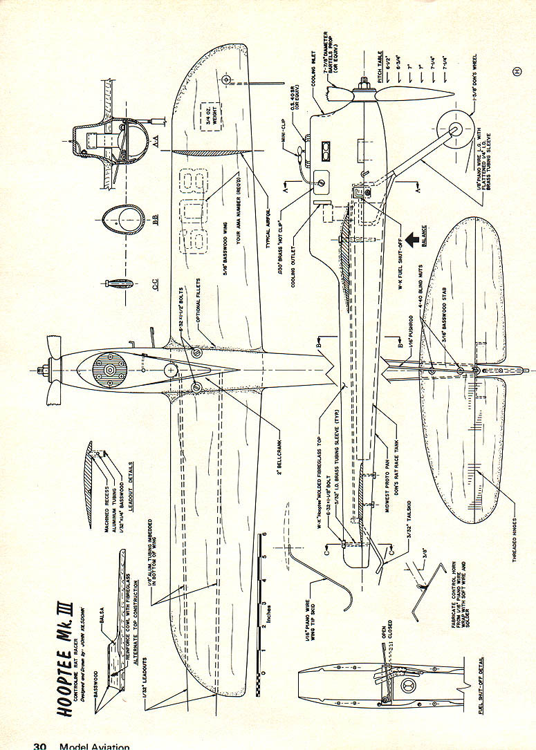
The wing material should be selected from light basswood or select ponderosa pine. In a pinch, I have used a board from a shipping crate. The wood should be planed and sanded to a 5/16" thickness. A 5/16" x 4" x 28" blank is required. Cut out the plan form of the wing to the configuration shown on the plans. The leadout tube grooves can be cut using a little care and an X-acto gouge. The easy way is to use a router. I bought a Sears standard router for about $30.00 and it sure saves time and gives a much cleaner finished product. When using a hand gouge the grooves need only be 1/8" wide and 1/8" deep. If you use a router, cut the grooves 5/32" deep using a 1/8" dia. blade. Then mill a 1/32" x 1/8" wide groove on top of that. This allows for a 1/32" x 1/8" basswood cap (available at model railroad supply stores). Whichever tube installation method is used, the 1/8" aluminum tubes should be held in place with a small amount of fiberglass (polyester) resin. The basswood caps are installed using the same material. If the caps are not used, fill in the balance of the grooves with plastic balsa or surfacing resin mixed with micro-balloons.
The outboard wing weight is a must for consistent performance, especially on windy days. Gouge—or use the router—a pocket 1/8" deep x 1/4" long x 7/8" wide as shown near outboard wing tip. This is filled with lead or solder in either of two ways. You can hammer a length of bar solder to an 1/8" thickness and then cut out a piece of this to fit in the pocket or you can do as I do by melting the solder and dripping it into the pocket. Drill about 1/32" diameter hole in the top of the wing to allow air to escape while filling. RAT RACING has evolved from a good beginner's event to a probably competitive control-line event in its 20-some years' existence. In the old days a form of aircraft acceptable for the long would take off and land; the winner usually could successfully restart the engine a couple of times during the race. Things have changed in recent years — the state-of-the-art has been upgraded both through technological improvements in engines and in flying techniques. These improvements have, in many cases, spelled the demise of participation. Participation, especially by new people, is practically non-existent. I feel the lack of participation by new blood is directly attributable to two areas: lack of available information and lack of pilots' intent. This article is intended to make available to the potential newcomer the details to get started in the event.
The Hooptee Mk. III model presented in this article — a typical modern rat racer — represents the third basic design change I have made in rat racer designs during the past 12 years. I have been using this design for three years and it has been such a consistent performer that other top competitors in the Midwest are now using it. These include Bill Allen, John Ballard, Gary Fentress, Bob Finley and Pat Flinn. It is quite easy to construct once you have gone through the exercise one time. The first time through may be a bit scary due to the unusual construction technique, namely the fiberglass top. Future models will become quite easy as your confidence improves.
The first step is to select an engine. As I write, the HP-40 RRV engine is popular. However, enough work is being put on the OS .40 FSR that someday it should, at least, rank equal to or better than the HP. Other .40-size engines are available; however the engine must possess both qualities absolutely necessary in a good rat engine: high performance and fast restart capability. Whatever engine you select, a starter should be fitted. The Midwest (formerly Harter's) Pinto speed pan can be obtained through a good hobby shop. The pan will require some grinding and engine-mount modifications. The pan should be kept to a minimum so as not to structurally weaken it. The engine is mounted using 4-40 screws which requires drilling and tapping the pan after locating the engine.
The next step is to install the landing gear. The single-wheel landing gear shown on the plans has proven very popular because of its ease of installation and extreme durability. An 1/8" hole is drilled through the inboard side at the dimple location in the pan. Another 1/8" hole is drilled approximately 1" rear of the wing mounting boss in the pan. Select a 1-5/8" to 1-3/4" length of 1/8" piano wire and make two right-angle bends in the same plane approximately in the middle of the piece. The center distance of the bends should correspond exactly to the center distance of the two landing-gear holes. Both holes drilled in the pan should be radiused on the top to accept the radius of the piano-wire bends. Slip the piano wire through the two holes and lightly tap into place until well seated.
Take the rearward wire and bend it forward as close to the pan as possible. Make another bend parallel and right against the back of the front wire. Take a length of brass tubing, gently flatten the ID cross-section in a vise, and slip it over the two pieces of piano wire; lightly tap into position. Mark the rear wire at the bottom edge of the brass tubing, remove the tubing and cut off the rear wire at the mark. Reinstall the tubing and bend the whole assembly forward. The wheel axle will be approximately 2" forward of the point where the front wire exits the pan. Measure from the engine-mounting surface of the pan down 4" to locate the wheel axle. Bend the forward 1/8" piano wire on the inboard side to a 90° angle parallel to the future wing centerline. Install 1/8" Don's wheels, soldering a No. 4 flat washer on both sides; trim off excess wire and use wheel collars to hold the wheel (tends to vibrate loose otherwise).
The next step is to install the fuel shut-off. The shut-off is located directly behind the engine. Leave enough clearance for the fuel lines to pass through. I use a W-K shut-off and find it the simplest and most effective. Using the shut-off you may find you can get closer to the engine by notching out extra clearance for the fuel line.
Next install the fuel tank. Either Don's 4-oz rat tank or the W-K rat tank will work very well. Personally I use a combination of both tanks: I cut off the front section of Don's tank and solder it to the W-K tank, which gives about a 4-oz capacity. A 4-oz tank is adequate for 60–70 lap engines. However, for security I prefer extra capacity. The fuel tank should be securely mounted to the pan using .020" brass angle brackets soldered to both front and rear of the tank. The tank is held in place with 4-40 bolts through the pan.
Hooptee MK III
six to eight holes through the weight and cross-wise into the wood about 1/8" deep.
Remove the weight and apply a generous amount of resin to the pocket. Reinstall the weight and clamp it in position. The resin will ooze out the holes and provide a good mechanical bond. This can also be covered with a patch of fiberglass cloth for reinforcement.
When all the resin has set up, use a sanding block to sand both the leadout tube area and the wing weight area to bring it back to a perfectly flat plane.
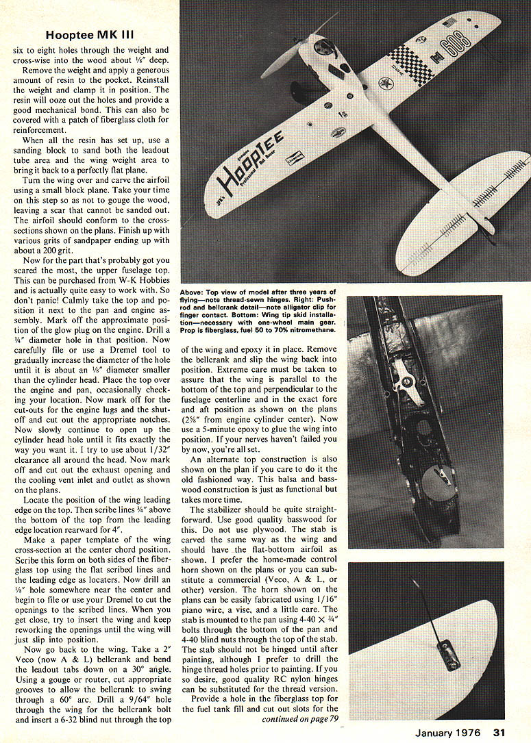
Turn the wing over and carve the airfoil using a small block plane. Take your time on this step so as not to gouge the wood, leaving a scar that cannot be sanded out. The airfoil should conform to the cross-sections shown on the plans. Finish up with various grits of sandpaper ending up with about a 200 grit.
Now for the part that's probably got you scared the most, the upper fuselage top. This can be purchased from W-K Hobbies and is actually quite easy to work with. So don't panic! Calmly take the top and position it next to the pan and engine assembly. Mark off the approximate position of the glow plug on the engine. Drill a 1/4" diameter hole in that position. Now carefully file or use a Dremel tool to gradually increase the diameter of the hole until it is about an 1/8" diameter smaller than the cylinder head. Place the top over the engine and pan, occasionally checking your location. Now mark off for the cut-outs for the engine lugs and the shut-off and cut out the appropriate notches. Now slowly continue to open up the cylinder head hole until it fits exactly the way you want it. I try to use about 1/32" clearance all around the head. Now mark off and cut out the exhaust opening and the cooling vent inlet and outlet as shown on the plans.
Locate the position of the wing leading edge on the top. Then scribe lines 3/4" above the bottom of the top from the leading edge location rearward for 4".
Make a paper template of the wing cross-section at the center chord position. Scribe this form on both sides of the fiberglass top using the flat scribed lines and the leading edge as locators. Now drill an 1/8" hole somewhere near the center and begin to file or use your Dremel to cut the openings to the scribed lines. When you get close, try to insert the wing and keep reworking the openings until the wing will just slip into position.
Now go back to the wing. Take a 2" Veco (now A & L) bellcrank and bend the leadout tabs down on a 30° angle. Using a gouge or router, cut appropriate grooves to allow the bellcrank to swing through a 60° arc. Drill a 9/64" hole through the wing for the bellcrank bolt and insert a 6-32 blind nut through the top of the wing and epoxy it in place. Remove the bellcrank and slip the wing back into position. Extreme care must be taken to assure that the wing is parallel to the bottom of the top and perpendicular to the fuselage centerline and in the exact fore and aft position as shown on the plans (2-5/8" from engine cylinder center). Now use a 5-minute epoxy to glue the wing into position. If your nerves haven't failed you by now, you're all set.
An alternate top construction is also shown on the plan if you care to do it the old fashioned way. This balsa and basswood construction is just as functional but takes more time.
The stabilizer should be quite straightforward. Use good quality basswood for this. Do not use plywood. The stab is carved the same way as the wing and should have the flat-bottom airfoil as shown. I prefer the home-made control horn shown on the plans or you can substitute a commercial (Veco, A & L, or other) version. The horn shown on the plans can be easily fabricated using 1/16" piano wire, a vise, and a little care. The stab is mounted to the pan using 4-40 x 3/4" bolts through the bottom of the pan and 4-40 blind nuts through the top of the stab. The stab should not be hinged until after painting, although I prefer to drill the hinge thread holes prior to painting. If you so desire, good quality RC nylon hinges can be substituted for the thread version.
Provide a hole in the fiberglass top for the fuel tank fill and cut out slots for the stabilizer in the top at the location shown. You can add fillets around the wing joint using either plastic balsa or micro-balloons, sanding to the desired contour. You should also dam up the upper fuselage area above the wing using either of these materials. This will prevent fuel from splashing into that area.
Now you have to locate again the top of the pan and drill a 7/64" hole through the top and wing assembly and through the pan at the indicated positions for the front hold-down screws. Similarly at the rear of the top for the rear hold-down position.
After drilling the 7/64" holes through the pan, tap these three holes with a 6-32 tap. Enlarge the 7/64" holes drilled through the top to 3/16" and cut off lengths of 3/16" O.D. x 5/32" I.D. brass tubing about 1-1/4" long. The tubing is then pushed through the holes in the top and the top is installed on the pan. Run three 6-32 x 2" bolts through the brass tubing and thread them into the pan. Draw all three bolts down tight making sure the brass tubing is seated against the pan. Now take masking tape or rubber bands and securely clamp the top to the pan. At this point, the brass tubing inserts should be extending well above the top. Apply a small amount of 5-minute epoxy to each tube at the top surface. This will hold the tubing in its proper position when the tape or rubber bands are removed.
After the epoxy is set, remove the top and turn it over. Additional (heavy amounts) of epoxy should be applied inside the top to securely hold the tubing in place. I lay a 3/4" x 1-1/2" strip of heavy fiberglass tape over the tubes under the wing and cement it with C/A to the top for additional reinforcement. You can use either epoxy or polyester resin to cement the tape in place. To securely hold the tube at the rear, I dam up the area about 1/4" in front of the tube (modeling clay works great for this) and pour in a mixture of micro-balloons and resin. When this sets up, it can easily be sanded flat (remove the clay before sanding). The excess tubing and original epoxy on the top side is then trimmed off. I use a 1/2" piloted end-mill in a drill press for this; however a countersink or Dremel can also be used effectively.
The finish I have found to be the easiest and most durable is to apply two coats of surfacing (polyester) resin to the wood surfaces and fillets, sanding generously after each coat. Also the fiberglass top must be sanded lightly to remove any mold release agent present. I then apply Hobby-poxy or K&B epoxy (usually two coats) and wet sand with 400 wet or dry sandpaper. Apply decals as desired and finish up with a coat of clear epoxy over everything.
The stab must now be hinged. I re-drill all of the hinge holes to remove the accumulated resin and paint and sew the hinge with V/A flying line or heavy carpet thread.
Mount a .030" brass wire pad on the cowl and connect a short length of #16 wire to it and run it through the cowl and up through the top and install a mini-alligator clip to it. This forms the lead for the pit battery connection. The pan grounded to the engine forms the other leg. The brass plate should be located so that it is comfortable and convenient for your thumb.
Install the bellcrank and leadouts wire. I prefer 1/32" piano wire for leadouts; however, flexible cable of 125# test is fine also. Use a small drop of Locktite on the bellcrank mounting screw to prevent it from coming loose. I use a wing tip skid on the outboard wing. Although this is not absolutely necessary, it reduces tail skid wear. The tip skid is formed from 1/16" piano wire and held in place with a 4-40 bolt and a blind nut. On the original aircraft I prefer to solder it to a small .020" brass plate and utilize two such screws to hold it in place.
Mount the stab using the 4-40 x 3/4" bolts through the pan and blind nuts in the stabilizer. Install the CG as shown on the plan (2-5/8" from engine cylinder center). Now use a 5-minute epoxy to glue the wing into position. If your nerves haven't failed you by now, you're all set. An alternate top construction is also shown on the plan if you care to do it the old fashioned way. This balsa and basswood construction is just as functional but takes more time. The stabilizer should be quite straightforward. Use good quality basswood for this. Do not use plywood. The stab is carved the same way as the wing and should have the flat-bottom airfoil as shown. I prefer the home-made control horn shown on the plans or you can substitute a commercial (Veco, A & L, or other) version. The horn shown on the plans can be easily fabricated using 1/16" piano wire, a vise, and a little care. The stab should not be hinged until after painting, although I prefer to drill the hinge thread holes prior to painting. If you so desire, good quality RC nylon hinges can be substituted for the thread version. Provide a hole in the fiberglass top for the fuel tank fill and cut out slots for the stabilizer in the top at the location shown. You can add fillets around the wing joint using either plastic balsa or micro-balloons, sanding to the desired contour. You should also dam up the upper fuselage area above the wing using either of these materials. This will prevent fuel from splashing into that area.
First step: select engine. As I write, the HP-40 RRV engine is popular. However, enough work is being put on the OS .40 series that some day it should at least rank equal to or better than the HP. Other 40-size engines are available; however, the engine must possess both qualities absolutely necessary in a good rat engine: high performance and fast restart capability.
Whatever engine you select, it should be fitted to a speed pan. The Midwest (formerly Harter's) Pinto speed pan can be obtained through any good hobby shop. The pan will require some grinding and engine-mount modifications. The pan should be kept to a minimum so as not to structurally weaken it. The engine is mounted using 4-40 screws which requires drilling and tapping the pan after locating the engine.
Next step: install landing gear. The single-wheel landing gear shown on the plans has proven very popular because of its ease of installation and extreme durability. An 1/8" hole is drilled through the inboard side at the dimple location in the pan. Another 1/8" hole is drilled approximately 1" rear of the wing mounting boss in the pan. Select a 15/18" length of 1/8" piano wire and make two right-angle bends in the same plane approximately in the middle piece. The center distance between the bends should correspond exactly to the center distance between the two landing gear holes. Both holes drilled in the pan should be radiused on the top to accept the radius of the piano wire bends. Slip the piano wire through the two holes and lightly tap into place until well seated.
Take the rearward wire and bend it forward as close to the pan as possible. Make another bend parallel and right against the back of the front wire. Take a length of brass tubing and gently flatten the I.D. in a vise. Slip it over the two pieces of piano wire and lightly tap into position. Mark the rear wire at the bottom edge of the brass tubing. Remove the tubing, cut off the rear wire at the mark. Reinstall the tubing and bend the whole assembly forward. The wheel axle will be approximately 2 inches in front of where the front wire exits the pan.
Measure from the engine mounting surface on the pan down 4 inches to locate the wheel axle. Bend forward 1/8" piano wire on the inboard side at a 90-degree angle parallel to the future wing centerline. Install 1/8" Don's wheel, soldering a No. 4 flat washer on both sides. Trim off excess wire. Use wheel collars to hold the wheel; they tend to vibrate loose.
Next step: install the fuel shut-off on the pan, located directly behind the engine. Leave enough clearance for the fuel lines to pass through. I use the W-K shut-off and find it the simplest and most effective. Using this shut-off you may find you can get it closer to the engine by notching out extra fuel line clearance.
Next, install the fuel tank. Either Don's 4 oz rat tank or the W-K rat tank will work very well. Personally I use a combination of both tanks — cut off the front section of Don's tank and solder to the W-K tank to give about a 4 oz capacity. A 4 oz tank is adequate for 60-70 lap engines. However, for security I prefer extra capacity. The fuel tank should be securely mounted to the pan using .020" brass angle brackets soldered to both front and rear of the tank and held in place with 4-40 bolts through the pan and tail skid.
Hooptee MK III (continued)
bolts and blind mounting nuts. Then run a 1/16" pushrod from the outside hole on the bellcrank to the control horn on the stab. You will have to experiment with different lengths of wire to get the proper movement. I like 45° up and 30° down.
When the controls are operating properly, a small pushrod must be fabricated to trip the fuel shut-off. Again I use a short length of 1/16" piano wire. This is connected to the inside hole on the bellcrank and runs through a small angle bracket mounted inside the cowl. Experiment with this length until the fuel shut-off will trip just prior to full down elevator. Now mount the top on the pan and you're ready to test fly.
I prefer a fiberglass prop pitched according to the details on the plans. Use a fuel with from 50% to 70% nitromethane and a good quality lubricant. Several new glow plugs are now available. Preliminary tests have indicated that the Glo-Bee (Fusite Div. of Emerson Elec.) has the best durability. You should experiment with different props, fuels, and glow plugs to determine what suits you the best.
On each take-off, it is mandatory to maintain neutral elevator until the model is airborne. You will find that a Hooptee built according to the plans is extremely stable and flies easily. The response to control may appear to be somewhat sluggish, but it is intended to be that way. Too often, in a heat race at 150 mph, a pilot will take his eyes off his model to watch for pit crew signals or to glance at the other model in the race, and he'll crash the plane because it was too sensitive to control.
In an effort to help potential new fliers get involved in rat race, the following is a list of where to get specialty items. You will find that most items are quite available and will help immensely in getting you started. I have personally dealt with all of these sources and can honestly recommend all of them. They also feature good mail order facilities.
W-K Hobbies, 19 N. Main, Centerville, Ohio 45459, (513) 433-0752. Fiberglass tops, rat tanks, fiberglass props, fuel, shut-offs, wheels and other hobby items.
Aldrich Products, Inc., P.O. Box 1426, Mission, Tex. 78572, (512) 585-7681. Engine rework, fuel, glow plugs, chrome plating.
Joes Hobby Centers, Inc., 7845 Wyoming Ave., Dearborn, Mich. 48126, (313) 993-6567. Bartels Props, Ucon & Klotz oil, premixed fuel, Don's products, and other standard hobby items.
Fusite Division, Emerson Electric Company, 6000 Fernview Ave., Cincinnati, Ohio 45212, (513) 731-2020. Glo-Bee Plugs.
Randy's Model Aeronautics, 515 Coleman Blvd., Mount Pleasant, S.C. 29464, (803) 884-7411. Fuels, distributor for Don's products and other hobby items.
Transcribed from original scans by AI. Minor OCR errors may remain.

