
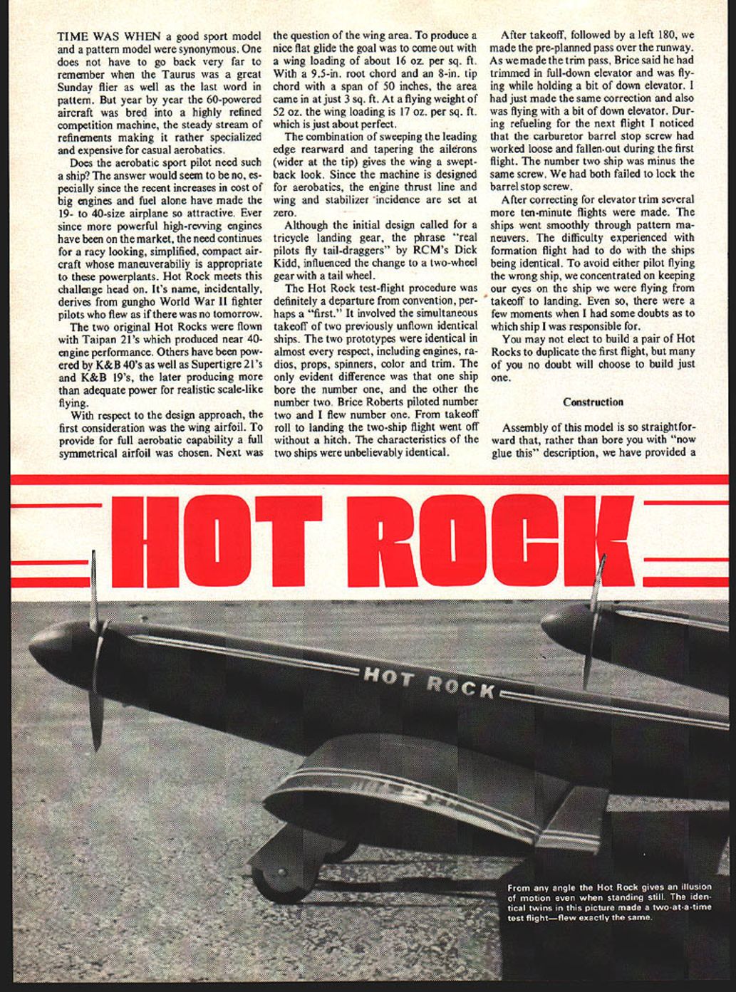
Hot Rock
TIME WAS WHEN a good sport model and a pattern model were synonymous. One does not have to go back very far to remember when the Taurus was a great Sunday flier as well as the last word in pattern. But year by year the 60-powered aircraft was bred into a highly refined competition machine, the steady stream of refinements making it rather specialized and expensive for casual aerobatics.
Does the acrobatic sport pilot need such a ship? The answer would seem to be no, especially since the recent increases in cost of big engines and fuel alone have made the 19- to 40-size airplane so attractive. Ever since more powerful high-revving engines have been on the market, the need continues for a racy-looking, simplified, compact aircraft whose maneuverability is appropriate to these powerplants. Hot Rock meets this challenge head on. Its name, incidentally, derives from gungho World War II fighter pilots who flew as if there was no tomorrow.
The two original Hot Rocks were flown with Taipan 21's which produced near 40-engine performance. Others have been powered by K&B 40's as well as Supertigre 21's and K&B 19's, the later producing more than adequate power for realistic scale-like flying.
With respect to the design approach, the first consideration was the wing airfoil. To provide for full aerobatic capability a full symmetrical airfoil was chosen. Next was the question of the wing area. To produce a nice flat glide the goal was to come out with a wing loading of about 16 oz. per sq. ft. With a 9.5-in. root chord and an 8-in. tip chord with a span of 50 inches, the area came in at just 3 sq. ft. At a flying weight of 52 oz. the wing loading is 17 oz. per sq. ft., which is just about perfect.
The combination of sweeping the leading edge rearward and tapering the ailerons (wider at the tip) gives the wing a swept-back look. Since the machine is designed for aerobatics, the engine thrust line and wing and stabilizer incidence are set at zero.
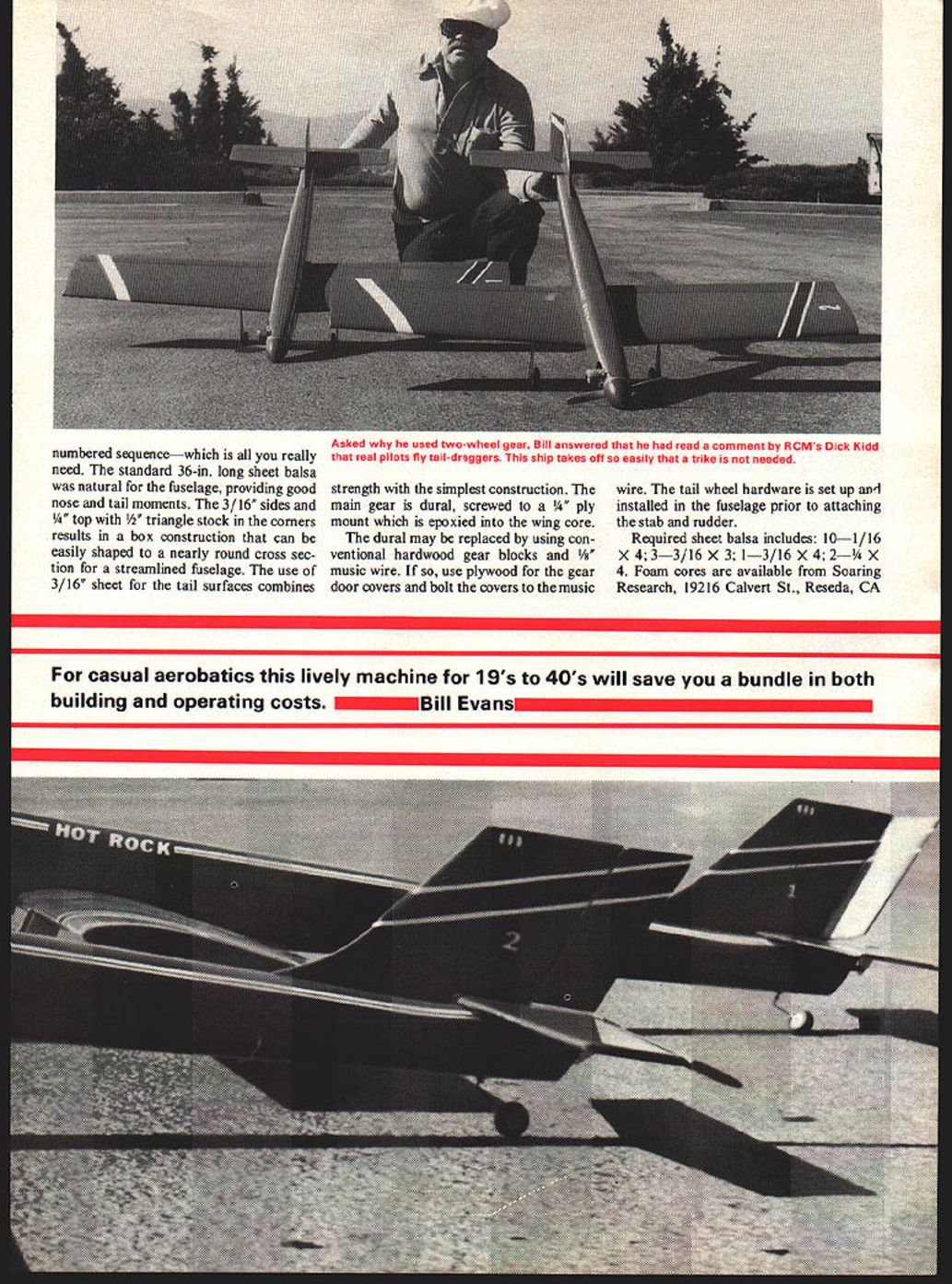
Although the initial design called for a tricycle landing gear, the phrase "real pilots fly tail-draggers" by RCM's Dick Kidd influenced the change to a two-wheel gear with a tail wheel.
The Hot Rock test-flight procedure was definitely a departure from convention, perhaps a "first." It involved the simultaneous takeoff of two previously unflown identical ships. The two prototypes were identical in almost every respect, including engines, radios, props, spinners, color and trim. The only evident difference was that one ship bore the number one, and the other the number two. Brice Roberts piloted number two and I flew number one. From takeoff roll to landing the two-ship flight went off without a hitch. The characteristics of the two ships were unbelievably identical.
After takeoff, followed by a left 180, we made the pre-planned pass over the runway. As we made the trim pass, Brice said he had trimmed in full-down elevator and was flying while holding a bit of down elevator. I had just made the same correction and also was flying with a bit of down elevator. During refueling for the next flight I noticed that the carburetor barrel stop screw had worked loose and fallen out during the first flight. The number two ship was minus the same screw. We had both failed to lock the barrel stop screw.
After correcting for elevator trim several more ten-minute flights were made. The ships went smoothly through pattern maneuvers. The difficulty experienced with formation flight had to do with the ships being identical. To avoid either pilot flying the wrong ship, we concentrated on keeping our eyes on the ship we were flying from takeoff to landing. Even so, there were a few moments when I had some doubts as to which ship I was responsible for.
You may not elect to build a pair of Hot Rocks to duplicate the first flight, but many of you no doubt will choose to build just one.
Construction
Assembly of this model is so straight-forward that, rather than bore you with "now glue this" description, we have provided a numbered sequence—which is all you really need. The standard 36-in. long sheet balsa was natural for the fuselage, providing good nose and tail moments. The 3/16" sides and 1/4" top with 1/2" triangle stock in the corners results in a box construction that can be easily shaped to a nearly round cross section for a streamlined fuselage. The use of 3/16" sheet for the tail surfaces combines
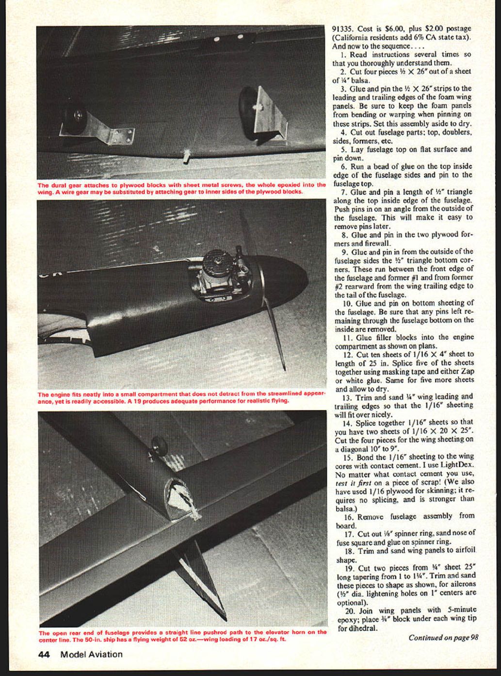
strength with the simplest construction. The main gear is dural, screwed to a 1/4" ply mount which is epoxied into the wing core. The dural may be replaced by using conventional hardwood gear blocks and 1/8" music wire. If so, use plywood for the gear door covers and bolt the covers to the music wire. The tail wheel hardware is set up and installed in the fuselage prior to attaching the stab and rudder.
Required sheet balsa includes: 10—1/16 x 4; 3—3/16 x 3; 1—3/16 x 4; 2—1/4 x 4. Foam cores are available from Soaring Research, 19216 Calvert St., Reseda, CA
For casual aerobatics this lively machine for 19's to 40's will save you a bundle in both building and operating costs. Bill Evans
- Cost is $6.00, plus $2.00 postage (California residents add 6% CA state tax).
And now to the sequence....
- Read instructions several times so that you thoroughly understand them.
- Cut four pieces 1/16" x 26" out of a sheet of 1/4" balsa.
- Glue and pin the 1/16" x 26" strips to the leading and trailing edges of the foam wing panels. Be sure to keep the foam panels from bending or warping when pinning on these strips. Set this assembly aside to dry.
- Cut out fuselage parts: top, doublers, sides, formers, etc.
- Lay fuselage top on flat surface and pin down.
- Run a bead of glue on the top inside edge of the fuselage sides and pin to the fuselage top.
- Glue and pin a length of 1/2" triangle along the top inside edge of the fuselage. Push pins in on an angle from the outside of the fuselage. This will make it easy to remove pins later.
- Glue and pin in the two plywood formers and firewall.
- Glue and pin in from the outside of the fuselage sides the 1/2" triangle bottom corners. These run between the front edge of the fuselage and former #1 and from former #2 rearward from the wing trailing edge to the tail of the fuselage.
- Glue and pin on bottom sheeting of the fuselage. Be sure that any pins left remaining through the fuselage bottom on the inside are removed.
- Glue filler blocks into the engine compartment as shown on plans.
- Cut ten sheets of 1/16" x 4" sheet to a length of 25 in. Splice five of the sheets together using masking tape and either Zap or white glue. Same for five more sheets and allow to dry.
- Trim and sand 1/4" wing leading and trailing edges so that the 1/16" sheeting will fit over nicely.
- Splice together 1/16" sheets so that you have two sheets of 1/16" x 20" x 25". Cut the four pieces for the wing sheeting on a diagonal 10" to 9".
- Bond the 1/16" sheeting to the wing cores with contact cement. I use LiteDex. No matter what contact cement you use, test it first on a piece of scrap! (We also have used 1/16" plywood for skinning; it requires no splicing, and is stronger than balsa.)
- Remove fuselage assembly from board.
- Cut out 1/2" spinner ring, sand nose of fuse square and glue on spinner ring.
- Trim and sand wing panels to airfoil shape.
- Cut two pieces from 1/4" sheet 25" long tapering from 1" to 1 1/4". Trim and sand these pieces to shape as shown, for ailerons (1/2" dia. lightening holes on 1" centers are optional).
- Join wing panels with 5-minute epoxy; place 3/4" block under each wing tip for dihedral.
Hot Rock
- Install strip aileron links to ailerons and cut out center-section blocks to allow for free movement of links.
- Layout 1/4" plywood landing gear blocks, rout out wing and 5-minute epoxy gear blocks in place.
- Cover wings and ailerons.
- Cut out and bend dural gear, then use screws to attach gear to plywood blocks.
- Install hinges and make aileron torque rods to fit aileron servo arms.
- Carve and sand fuselage to shape.
- The tail surfaces are cut from 3/16" sheet balsa. Cut and sand to shape.
- Apply your choice of covering; the original was covered with red Solarfilm.
- Make radio, engine, and tank installation as shown on plans.
We hope you have as much satisfaction with your Hot Rock as we did with the prototype.
Transcribed from original scans by AI. Minor OCR errors may remain.

