
Hot Wood
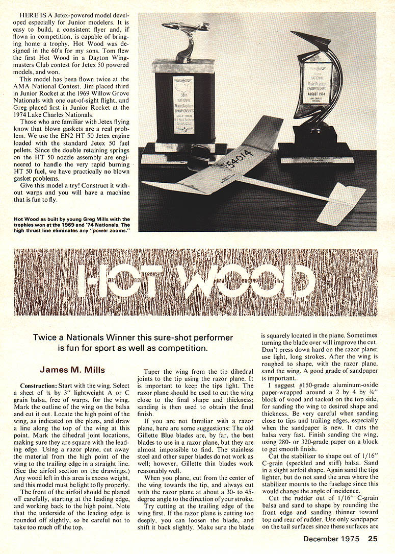
HERE IS a Jetex-powered model developed especially for Junior modelers. It is easy to build, a consistent flyer and, if flown in competition, is capable of bringing home a trophy. Hot Wood was designed in the 60's for my sons. Tom flew the first Hot Wood in a Dayton Wingmasters Club contest for Jetex 50 powered models, and won.
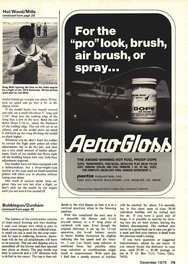
This model has been flown twice at the AMA National Contest. Jim placed third in Junior Rocket at the 1969 Willow Grove Nationals with one out-of-sight flight, and Greg placed first in Junior Rocket at the 1974 Lake Charles Nationals.
Those who are familiar with Jetex flying know that blown gaskets are a real problem. We use the EN2 HT 50 Jetex engine loaded with the standard Jetex 50 fuel pellets. Since the double retaining springs on the HT 50 nozzle assembly are engineered to handle the very rapid burning HT 50 fuel, we have practically no blown gasket problems.
Give this model a try! Construct it without warps and you will have a machine that is fun to fly.
Twice a Nationals Winner this sure-shot performer is fun for sport as well as competition.
James M. Mills
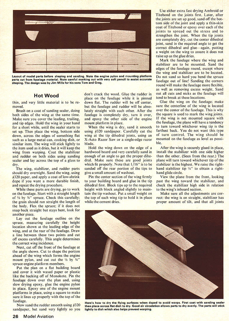
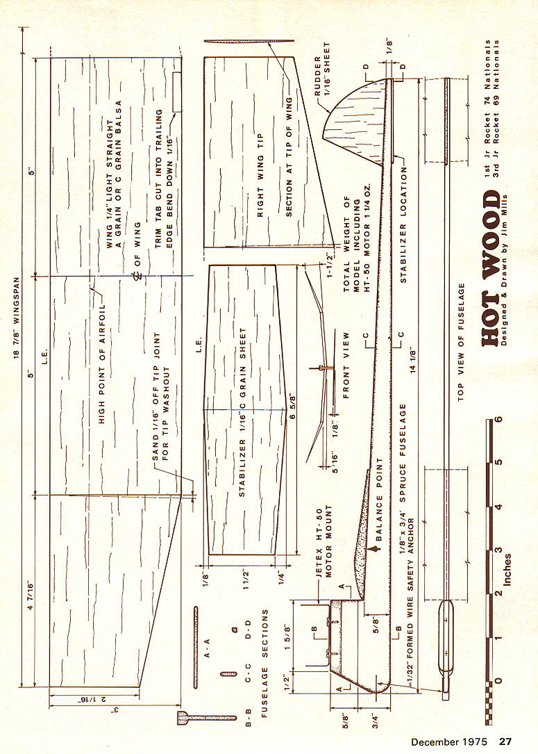
Construction: Start with the wing. Select a sheet of 4 by 3" lightweight A- or C-grain balsa, free of warps, for the wing. Mark the outline of the wing on the balsa and cut it out. Locate the high point of the wing, as indicated on the plans, and draw a line along the top of the wing at this point. Mark the dihedral joint locations, making sure they are square with the leading edge. Using a razor plane, cut away the material from the high point of the wing to the trailing edge in a straight line. (See the airfoil section on the drawings.) Any wood left in this area is excess weight, and this model must be light to fly properly.
The front of the airfoil should be planed off carefully, starting at the leading edge and working back to the high point. Note that the underside of the leading edge is rounded off slightly, so be careful not to take too much off the top.
Taper the wing from the tip dihedral joints to the tip using the razor plane. It is important to keep the tips light. The razor plane should be used to cut the wing close to the final shape and thickness; sanding is then used to obtain the final finish.
If you are not familiar with a razor plane, here are some suggestions: The old Gillette Blue blades are, by far, the best blades to use in a razor plane, but they are almost impossible to find. The stainless steel and other super blades do not work as well; however, Gillette thin blades work reasonably well.
When you plane, cut from the center of the wing towards the tip, and always cut with the razor plane at about a 30- to 45-degree angle to the direction of your stroke. Try cutting at the trailing edge of the wing first. If the razor plane is cutting too deeply, you can loosen the blade and shift it back slightly. Make sure the blade is squarely located in the plane. Sometimes turning the blade over will improve the cut. Don't press down hard on the razor plane; use light, long strokes. After the wing is roughed to shape with the razor plane, sand the wing. A good grade of sandpaper is important.
I suggest #150-grade aluminum-oxide paper—wrapped around a 2 by 4 by 3/4" block of wood and tacked on the top side—for sanding the wing to the desired shape and thickness. Be very careful when sanding close to tips and trailing edges, especially when the sandpaper is new. It cuts the balsa very fast. Finish sanding the wing using 280- or 320-grade paper on a block to get the smooth finish.
Cut the stabilizer to shape out of 1/16" C-grain (speckled and stiff) balsa. Sand in a slight airfoil shape. Again sand the tips lighter, but do not sand the area where the stabilizer mounts to the fuselage since this would change the angle of incidence.
Cut the rudder out of 1/16" C-grain balsa and sand to shape by rounding the front edge and sanding thinner toward top and rear of rudder. Use only sandpaper on the tail surfaces since these surfaces are thin; very little material should be removed. Brush coat with sanding sealer, doing both sides of the wing at the same time. Make sure to cover leading, trailing and tip edges. Hold the wing by hand until sealer starts to set up; then place the wing bottom side down across the edges of something flat such as a large metal can, cooking dish, or similar item. The wing will stick lightly to the item used while it dries and will keep the wing from warping.
Coat stabilizer and rudder both sides using sanding sealer; lay across top of glass to dry. Wing, stabilizer and rudder parts should dry overnight. Sand the wing using #320 paper; apply a coat of low-shrink dope if you want a durable finish. Repeat the drying procedure. After parts are drying, go to work on the fuselage.
Start with a straight length of 1/8 by 3/8" spruce. Check carefully; the grain should run the length of the body. If the flexed spruce does not snap back straight and stays bent, look for another piece. Lay out the fuselage outline on the spruce, measuring carefully for height and location shown (leading edge of wing, rear fuselage). Draw a line between two points and cut off excess carefully; the angle determines correct wing incidence. Next cut off front fuselage angle shown Cut to shape the portion ahead of the wing which forms the engine mount pylon, and cut out the 1/8 by 1/4" spruce engine platform members.
Put the plane on a flat building board and cover it with waxed paper or plastic like the backing off of Monokote. Pin the fuselage down over the plan and, using slow-drying epoxy, glue the engine pylon in place. Epoxy one of the engine mount platform members in place, using a square to make sure it lines up properly with the top of the fuselage.
Now sand the rudder smooth using #320 sandpaper, but sand very lightly so you don't crack the wood. Glue the rudder in place on the fuselage while it is pinned down flat. The rudder will be off center, but the fuselage and rudder will be absolutely straight with each other. After the fuselage is completely dry, turn it over and epoxy the other side of the engine mount platform in place.
When the wing is dry, sand it smooth using #320 sandpaper. Carefully cut the wing at the tip dihedral joints, using an X-Acto Razor Saw or a single-edge razor blade.
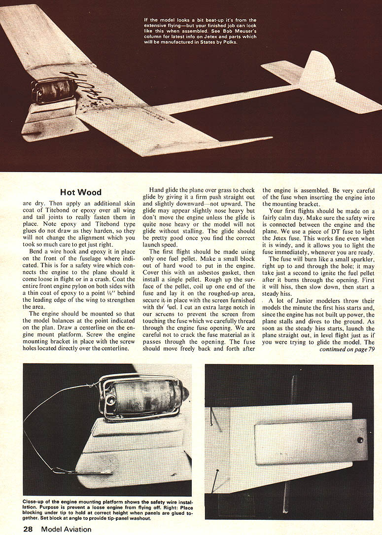
Hold the wing down on the edge of a hardwood board and very carefully sand in enough of an angle to get the proper dihedral. Make sure these are good joints which fit properly. Note that 1/16" is to be sanded off the rear portion of the tips to give a small amount of washout.
Pin the center section of the wing firmly to your building board and glue in the tip dihedral first. Block tips up to the required height with block angled slightly to maintain the tip washout. Put a small weight on top of each wing tip to hold it in place while the cement dries.
Use either extra fast-drying Ambroid or Titebond on the joints first. Later, after the joints are set up good, sand off the bottom side of the joint and apply a thin-skin coat of Titebond or epoxy over each of the joints to spread out the stress and to strengthen the joint. When the tip joints are completely dry, cut the center dihedral joint, sand in the required angle to get the correct dihedral and glue—again, putting a weight on the wing to assure it does not raise up as the glue dries.
Mark the fuselage where the wing and stabilizer are to be mounted. Sand the edges of the fuselage round, except where the wing and stabilizer are to be located. Do not sand so hard you bend the spruce fuselage out of line! Sanding the corners round will make the fuselage more flexible, as well as removing excess weight. Sand out all cuts and nicks as the fuselage will tend to break at these locations.
Glue the wing on the fuselage; make sure the centerline of the wing is located over the center of the fuselage. This is why the square is used to mark the wing joints. If the wing is not mounted square with the fuselage, the plane will have a tendency to turn toward whichever wing tip is the farthest back. You do not want this type of turn control. The wing should be mounted on the fuselage as level as possible.
After the wing is securely glued in place, install the stabilizer with one side higher than the other. (Seen from the rear.) The plane will then turn toward whichever tip of the stabilizer is the highest. We raise the right-hand stabilizer tip 1/8" to obtain a right-hand glide circle.
View the plane from the front, looking past the wing toward the stabilizer, and check the stabilizer high side in relation to the wing's inboard section.
Make sure all the adjustments are correct: the wing is on straight, stabilizer has proper amount of tilt, and that all joints are secure.
Construction
Start wing
Select 1/16" lightweight C-grain balsa free of warps. Mark wing outline on balsa and cut out. Locate high point of airfoil indicated on plans; draw line along top wing point. Mark dihedral joint locations, making sure square. Using a razor plane, cut away material from the high point toward the trailing edge in a straight line. See airfoil section drawings. Any wood left in this area is excess weight — the model must be light to fly properly. The front of the airfoil should be planed off carefully starting at the leading edge and working back to the high point. Note underside leading edge is rounded off slightly; be careful not to take too much off the top. Taper wing tips at dihedral joints; tip using a razor plane. It is important to keep tips light. A razor plane should be used to cut the wing close to final shape; sanding is used to obtain the final finish.
Familiarity with the razor plane is important. Some suggestions: old Gillette Blue blades are by far the best blades to use in a razor plane. Stainless steel blades are almost impossible to find; other "super" blades work well; however, Gillette thin blades work reasonably well. Plane the center wing towards the tip; always hold the razor plane about a 30°–45° angle to the direction of the stroke. Try cutting the trailing edge of the wing first. Razor plane cutting too deeply can loosen the blade; if it does, shift it back slightly. Make sure the blade is squarely located in the plane. Sometimes turning the blade over will improve the cut. Don't press down hard on the razor plane; use light, long strokes.
After the wing is roughed to shape with the razor plane, sand the wing with good grade sandpaper. I suggest #150-grade aluminum-oxide paper wrapped around a 2–4" wood block tacked to the top side and sand the wing to the desired shape and thickness. Be very careful sanding close to tips and trailing edges — sandpaper cuts new balsa very fast. Finish sanding the wing using 280–320-grade paper on a block to get a smooth finish.
Cut stabilizer shape out of 1/16" C-grain speckled stiff balsa. Sand a slight airfoil shape. Again sand tips lighter. Sand the area where the stabilizer mounts the fuselage since this will change the angle of incidence. Cut the rudder out of 1/16" C-grain balsa. Sand shape, rounding the front edge and sanding thinner toward the top rear of the rudder. Use sandpaper on the tail surfaces since the surfaces are thin; remove very little material.
Brush a coat of sanding sealer on both sides of the wing at the same time. Make sure to cover the leading, trailing and tip edges. Hold the wing in the hand for a short time until the sealer starts to set up, then place the wing bottom side down across the edges of something flat — such as a large metal can, cooking dish or similar item. The wing will stick lightly to the item used while it dries and this will keep the wing from warping. Coat stabilizer and rudder both sides using sanding sealer. Lay across top of glass to dry. Wing, stabilizer and rudder parts should dry overnight. Sand the wing using #320 paper and apply a coat of low-shrink clear dope if you want a durable finish. Repeat drying procedure.
While parts are drying, go work on the fuselage.
Start with a straight length of spruce. Check carefully; the grain should run the length of the body. If the spruce flexes and does not snap back straight (stays bent), select another piece. Lay out the fuselage outline on the spruce, measuring carefully the height and location shown (leading edge of wing to rear fuselage). Draw a line between the two points and cut off the excess carefully; this angle determines the correct wing incidence. Next cut off the front fuselage angle shown.
Hot Wood
Bend a wire hook and epoxy it in place on the front of the fuselage where indicated. This is for a safety wire which connects the engine to the plane should it come loose in flight or in a crash. Coat the entire front engine pylon on both sides with a thin coat of epoxy to a point 1/8" behind the leading edge of the wing to strengthen the area.
The engine should be mounted so that the model balances at the point indicated on the plan. Draw a centerline on the engine mount platform. Screw the engine mounting bracket in place with the screw holes located directly over the centerline.
Hand glide the plane over grass to check glide by giving it a firm push straight out and slightly downward — not upward. The glide may appear slightly nose heavy but don't move the engine unless the glide is quite nose heavy or the model will not glide without stalling. The glide should be pretty good once you find the correct launch speed.
The first flight should be made using only one fuel pellet. Make a small block of hard wood to put in the engine. Cover this with an asbestos gasket, then install a single pellet. Rough up the surface of the pellet, coil up one end of the fuse and lay it on the roughed-up area, secure it in place with the screen furnished with the fuel. I cut an extra large notch in our screens to prevent the screen from touching the fuse which we carefully thread through the engine fuse opening. We are careful not to crack the fuse material as it passes through the opening. The fuse should move freely back and forth after the engine is assembled. Be very careful of the fuse when inserting the engine into the mounting bracket.
Your first flights should be made on a fairly calm day. Make sure the safety wire is connected between the engine and the plane. We use a piece of DT fuse to light the Jetex fuse. This works fine even when it is windy, and it allows you to light the fuse immediately, whenever you are ready. The fuse will burn like a small sparkler, right up to and through the hole; it may take just a second to ignite the fuel pellet after it burns through the opening. First it will hiss, then slow down, then start a steady hiss.
A lot of Junior modelers throw their models the minute the first hiss starts and, since the engine has not built up power, the plane stalls and dives to the ground. As soon as the steady hiss starts, launch the plane straight out, in level flight just as if you were trying to glide the model. The
Hot Wood
model should go straight out about 30 feet, pick up speed and go into a 30- or 40-degree climb.
If the model banks too steeply toward one side, cut a small tab about 3/4" long and 3/16" deep into the trailing edge of the wing that is low in the turn. Bend the tab down about 1/16", about the thickness of the trailing edge. The tab will act as an aileron, and as the model picks up speed it will hold up the wing allowing the model to climb higher.
Whatever you do, don't bend the rudder to correct the flight path unless all other adjustments fail to do the job, and then use a very small amount of rudder adjustment. Each of our models has flown right off the building board with very little final adjustment required.
Our models have not been equipped with a dethermalizer, but a drop-weight type similar to the type used on hand-launched gliders will allow you to practice without losing your plane.
One word of caution about Jetex engines: they are very hot after a flight, so don't pick up the model by the engine until you are sure it has cooled off.
Transcribed from original scans by AI. Minor OCR errors may remain.

