
Hotrodding the O.S. 20 4-Stroke
John Van't-Haaff
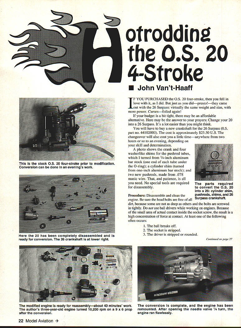
If you purchased the O.S. 20 four-stroke, then you fell in love with it, as I did. But just as you did—presto!—they came out with the 26 Surpass; virtually the same weight and size, with more power. Curses—foiled again!
If your budget is a bit tight, there may be an affordable alternative. Here may be the answer to your prayers: change your 20 into a 26 Surpass. It's a lot easier than you might think.
You will have to buy a new crankshaft for the 26 Surpass (O.S. part no. 44102000). The cost is approximately $25.50 U.S. The changeover will also cost you a little time—anywhere from two hours or so to an evening, depending on your skill and determination.
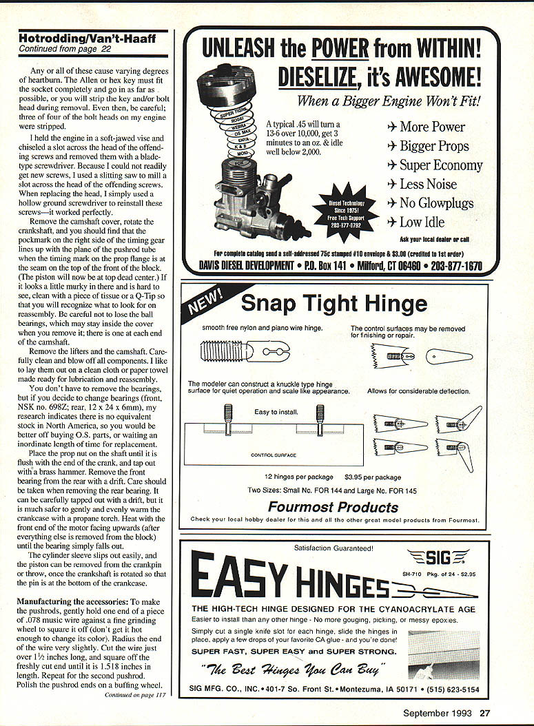
A photo shows the crank and four washerlike shims for the pushrod tubes, which I turned from 1/4-inch aluminum bar stock (one end of each tube under the O-ring); a cylinder shim (turned from one-inch aluminum bar stock); and two new pushrods, made from .078 music wire. That, and patience, is all you need. No special tools are required for disassembly.
Procedure
Disassemble and clean the engine. Be sure the head bolts are free of all dirt, because some are not as deep as others and the bolts are screwed in tightly. Do not use ball drivers while working on engines. Because of the small area of actual contact inside the socket screw, the result is a high concentration of force at contact. At least one of the following often occurs:
- The ball breaks off.
- The socket is stripped.
- The driver is stripped or rounded.
Any or all of these cause varying degrees of heartburn. The Allen or hex key must fit the socket completely and go in as far as possible, or you will strip the key and/or bolt head during removal. Even then, be careful: three or four of the bolt heads on my engine were stripped.
I held the engine in a soft-jawed vise and chiseled a slot across the head of the offending screws and removed them with a bladed-type screwdriver. Because I could not readily get new screws, I used a slitting saw to mill a slot across the head of the offending screws. When replacing the head, I simply used a hollow-ground screwdriver to reinstall these screws—it worked perfectly.
Remove the camshaft cover, rotate the crankshaft, and you should find that the pockmark on the right side of the timing gear lines up with the plane of the pushrod tube when the timing mark on the prop flange is at the seam on the top front of the block. (The piston will now be at top dead center.) If it looks a little murky in there and is hard to see, clean with a piece of tissue or a Q‑Tip so that you will recognize what to look for on reassembly. Be careful not to lose the ball bearings, which may stay inside the cover when you remove it; there is one at each end of the camshaft.
Remove the lifters and the camshaft. Carefully clean and blow off all components. I like to lay them out on a clean cloth or paper towel made ready for lubrication and reassembly.
You don't have to remove the bearings, but if you decide to change bearings (front, NSK no. 698Z; rear, 12 x 24 x 6 mm), my research indicates there is no equivalent stock in North America, so you would be better off buying O.S. parts, or waiting an inordinate length of time for replacement.
Place the prop nut on the shaft until flush with the end of the crank, and tap out with a brass hammer. Remove the front bearing with a drift. Care should be taken when removing the rear bearing. It can be carefully tapped out with a drift, but it is much safer to gently and evenly warm the crankcase with a propane torch. Heat with the front end of the motor facing upwards (after everything is removed from the block) until the bearing simply falls out.
The cylinder sleeve slips out easily, and the piston can be removed from the crankpin or throw once the crankshaft is rotated so that the pin is at the bottom of the crankcase.
Manufacturing the accessories
To make the pushrods:
- Gently hold one end of a piece of .078 music wire against a fine grinding wheel to square it off (don't get it hot enough to change its color). Radius the end of the wire very slightly.
- Cut the wire just over 1-1/2 inches long; square off the freshly cut end until it is 1-5/8 inches in length.
- Repeat for the second pushrod.
- Polish the pushrod ends on a buffing wheel.
Make spacers for each end of the pushrod tube from 1/4-inch aluminum bar stock. Face, center drill, and drill out .182 inches, deep enough so that you can cut off four .030 spacers. You could also use copper, aluminum, or brass heavy-wall tubing. Almost anything, including a second O-ring, will do the job, as long as it does not cut into the O-ring.
The cylinder spacer is made from one-inch aluminum bar stock turned to approximate 9/64 O.D. (or as convenient) and bored to .802 I.D. Cut so that it is .060 long. A friend of mine (who, by the way, used only a drill press for the entire operation) used a piece of .060 plate for his cylinder spacer. It requires a little drilling, cutting, and filing, but it can be done successfully; it just takes longer. The drill press can also act as a bearing presser, if necessary.
We found that the necessary clearance in these bearings was .005 inch per 1/2-inch diameter. In other words, a one-inch-diameter bearing would have needed .010-inch clearance between the diameters, not the radius. This same ratio holds pretty true even for smaller bearings, so a crankpin with .200-inch diameter should have .002-inch clearance—awfully close to what Col. Thacker says. Bill Wisniewski says up to .006-inch is good, so a rattle is okay. Check your conrods; it may save your engine.
Reassembly
- The 26 crank uses the collar from the 20 shaft, and together they slide easily into the crankcase. Tap the crank forward with a brass drift until it bottoms out with the front bearing. (Support the front end against a hardwood or aluminum block.)
- Slide the piston into the cylinder, rotate the crank until the conrod pin is at the bottom, and slip the conrod onto the pin.
- Rotate the crank to TDC (top dead center) and slide the .060 shim over the cylinder liner until it is tight underneath the flange at the top.
- Now slide the liner carefully over the piston and push it all the way down.
- With the engine on its left side, place a ball in the bottom of the cam recess, and insert the camshaft with the pockmark facing out. Take care to align the pockmark as previously indicated (in line with the pushrod tubes).
- Place the second ball on the end of the shaft, and secure the end cover in place.
- Replace the lifters.
- Remove O-rings from pushrod tubes. Slide the .030 spacers on each end, then replace the O-rings. Insert the pushrod tubes.
- Slip on the cylinder head, align and snug the four head bolts evenly in rotation.
- Insert the new pushrods, and reinstall the rocker assembly.
- With the tappets slacked off, rotate the crankshaft, and check the lifter operation. At TDC of the compression stroke, set the valve clearances.
- Replace the tappet cover and reinstall the carburetor and intake tube. You will notice that the screw that holds the intake tube to the cylinder near the carburetor is now out of alignment. Don't worry; it functions anyway.
Reinstall the engine in your aircraft or on your test bed and fire it up. Presto! Changeo! It takes longer to tell about it than it does to do it—well, almost.
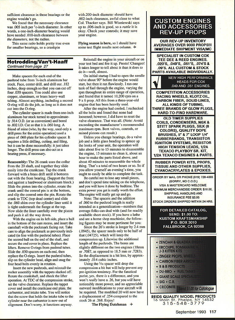
On initial startup I had to open the needle valve about 90° before the engine would start, but then it ran flawlessly. I ran one tank of fuel through the engine, varying the rpm throughout its entire range of operation, and found that it turned 10,200 rpm on a 9 x 6 prop. All this from a three-year-old engine that has been heavily used.
After the engine had cooled, I rechecked all the bolts and found that none had loosened; however, I did have to reset the valve clearance. That was all.
Note: Avoid exceeding the manufacturer's recommended maximum rpm. Bent valves, conrods, or ruined pistons can result.
Unless you change bearings, do a valve job, and a little glass beading to spruce up the looks of your unit, the operation will take about five to 15 minutes to disassemble the engine, 15 minutes to clean it, about an hour to make the parts listed above, and about 40 minutes to reassemble the whole thing. That's a total of two hours or so. So if you allow yourself an evening's time, you ought to easily be able to complete the task.
Be careful not to lose any small pieces, and don't spend time talking on the telephone, and you will have it done by bedtime. The extra power you get is really worth the effort. The engine will really get up and go.
Note: The spacers and the addition of .060 to the pushrod length is really intended as a generalization—numbers that average folks can deal with (and for readily available sheet stock). If you have a lathe and are a home-shop machinist, the following figures may be more pertinent for you:
- Since the 26's stroke is longer by 2.4 mm (.0945 in), the spacer needs only to be half of that (.04725 in), which will keep the compression up. Likewise the additional length of the pushrods.
- The bores are slightly different on the two engines (18.0 mm or .7087 in, as opposed to 18.5 mm or .7283 in). So the displacement is a bit less, by approximately .014 cubic inches.
- Using the 1/16-inch spacer will drop the compression a bit but will help prevent any pre-ignition tendency.
For the fanatic, push it—yes, there is a difference, and you won't really have a .26, but you will have noticeably more power, and no appreciable outward modifications to your aircraft will be required. The modified 20 will now have a displacement of .254 compared to the stock 20 at .268. Enjoy!
The Flying Dutchman
Transcribed from original scans by AI. Minor OCR errors may remain.

