
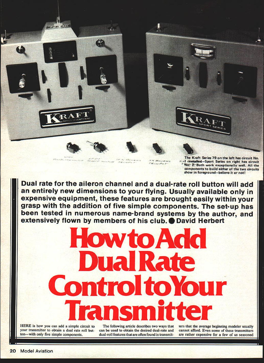
How to Add Dual Rate Control to Your Transmitter
David Herbert
Dual rate for the aileron channel and a dual-rate roll button will add an entirely new dimension to your flying. Usually available only in expensive equipment, these features are brought easily within your grasp with the addition of five simple components. The set-up has been tested in numerous name-brand systems by the author and extensively flown by members of his club.
Here is how you can add a simple circuit to your transmitter to obtain a dual-rate roll button—with only five simple components.
The following describes two ways to obtain the dual-rate and dual-roll features often found in higher-end transmitters. What prompted these circuits was my newest airplane, the Astron (Bill Evans, Model Aviation, April 1979). The Astron is an X-wing flying wing with elevon controls and an outstanding roll rate. Using the sliding-tray elevon control, I found the aileron control could not be mechanically reduced without also reducing the elevator portion. This circuit solves that problem electronically.
Benefits and advantages
- The circuits are not installed in the radio frequency portion of the transmitter, so there is no concern about detuning the system.
- Placing the aileron (or rudder, for 3-channel flyers) into half-rate reduces servo movement by half, making sensitive airplanes easier for beginners to fly and improving smoothness for pattern flying.
- Maintaining a precise constant roll rate during consecutive rolls is achieved with a roll button; only elevator is needed to maintain level flight through the maneuver.
- By switching to half rate and pressing the roll button, a slow roll will be performed; in full-rate mode the same button produces a full roll. The roll rate amount is adjustable.
- Installation is easy and can be completed in less than an hour; no electronic experience is needed beyond basic soldering. If you cannot solder, get help.
- The amount of half-rate desired is adjustable.
Note: I have installed this circuit in an MRC 6-channel radio, three Cirrus 4-channel radios, a Cox Sanwa 4-channel radio, an 8-channel Heathkit (with pluggable frequency modules), a Kraft KPT4A radio, and a Series 79, 7-channel Kraft. They all worked well and worked the first time.
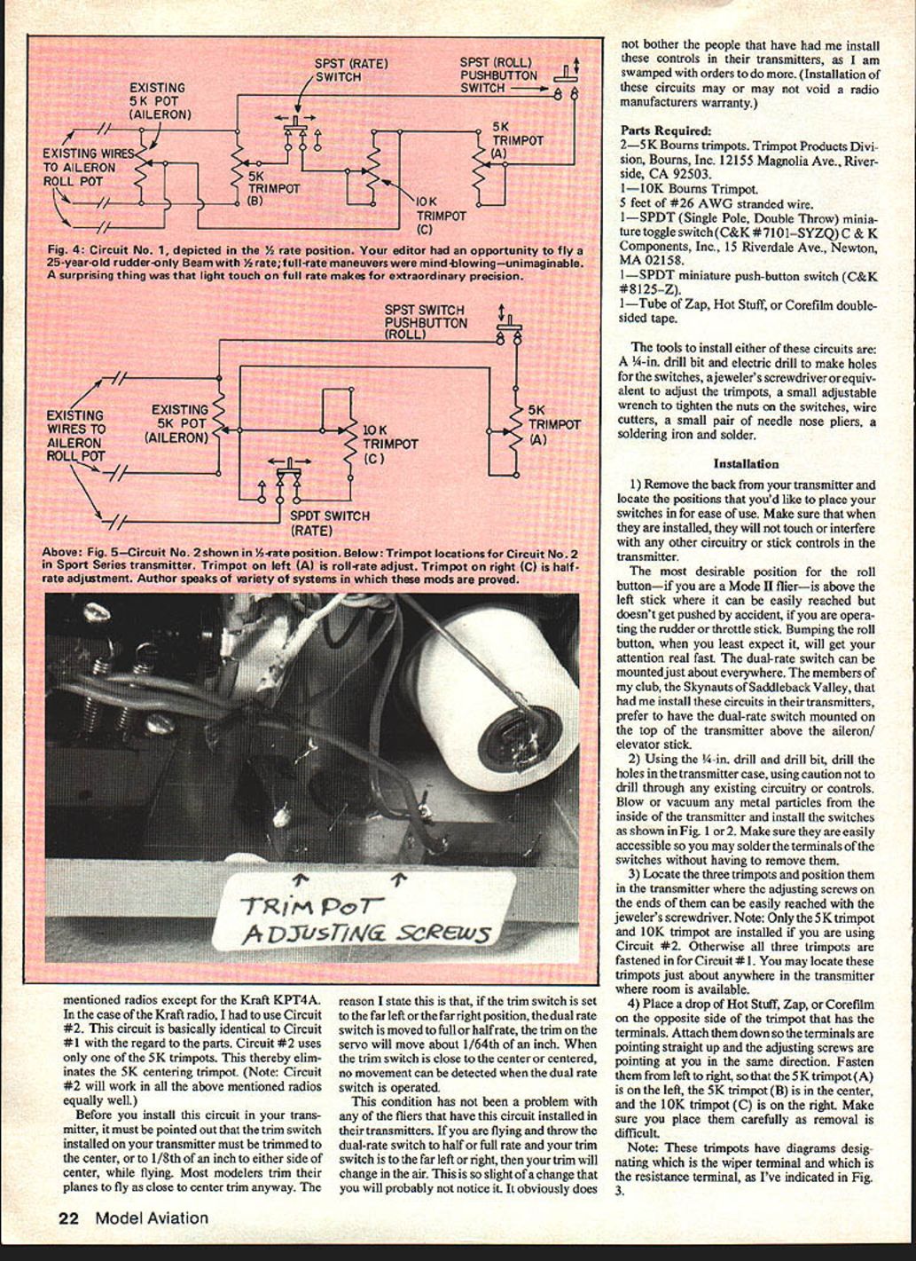
Circuit #1 works well in all the above radios except the Kraft KPT4A. For that radio use Circuit #2. Circuit #2 is basically identical in parts but uses only one 5K trimpot (it eliminates the 5K centering trimpot). Circuit #2 will work in all the radios mentioned.
Before you install this circuit, the trim switch on your transmitter must be set to center (or within 1/8 inch of center) while flying. If the trim is far left or right, switching dual-rate may produce a tiny trim change (about 1/64 inch); this is usually negligible but is worth noting. Installation of these circuits may or may not void a radio manufacturer's warranty.
Parts Required
- 2 — 5K Bourns trimpots (Trimpot Products Division, Bourns, Inc., 12155 Magnolia Ave., Riverside, CA 92503).
- 1 — 10K Bourns trimpot.
- 5 feet of #26 AWG stranded wire.
- 1 — SPDT miniature toggle switch (C&K #7101—SYZQ). C & K Components, Inc., 15 Riverdale Ave., Newton, MA 02158.
- 1 — SPDT miniature push-button switch (C&K #8125—Z).
- 1 — Tube of Zap, Hot Stuff, or Corefilm double-sided tape.
Tools
- 1/4-inch drill bit and electric drill (for switch holes)
- Jeweler's screwdriver (for trimpots)
- Small adjustable wrench (to tighten switch nuts)
- Wire cutters
- Small needle-nose pliers
- Soldering iron and solder
Installation (General)
- Remove the back from your transmitter and choose positions for the switches so they are easy to use and will not touch or interfere with circuitry or stick controls. For Mode II pilots, the roll button is best above the left stick; the dual-rate switch is often mounted on top above the aileron/elevator stick.
- Using the 1/4-inch drill bit, drill holes for the switches, taking care not to drill into circuitry. Clean metal particles from inside the transmitter and install the switches (see Fig. 1 or 2). Make sure they are accessible for soldering.
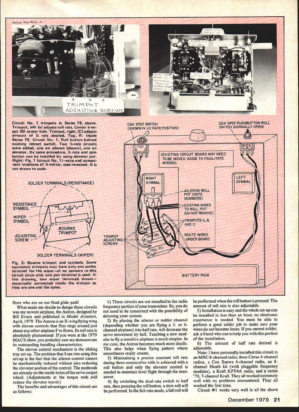
- Locate the trimpots and position them so their adjusting screws can be reached. For Circuit #2, only the 5K (A) and 10K (C) trimpots are used. For Circuit #1, all three trimpots are used (5K A, 5K B, 10K C). Glue them in place so terminals point up and adjusting screws point toward you (left to right: 5K A, 5K B, 10K C).
- Note the trimpot terminal diagrams (wiper and resistance terminals) for correct wiring.
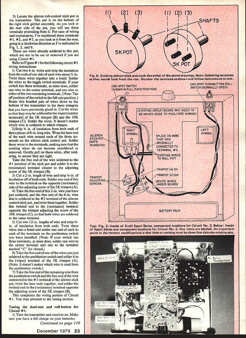
- Locate the aileron roll-control stick pot (bottom of the right stick gimbal assembly). From the rear, number the three terminals #1, #2, #3 clockwise (as shown in Fig. 1, 2, and 6). There are wires already soldered to this pot—do not remove them for Circuit #1.
Circuit #1 — Wiring Instructions
Refer to Figure 1 for terminal orientation and wiring locations.
- Cut two 6-inch wires. Strip 1/4 inch from one end of each, twist those stripped ends together and solder to the toggle switch terminals: one to the center terminal and one to either remaining terminal (if your switch has three terminals). Route the braided pair down to the trimpots and cut to length so they can be soldered to the wipers (center terminals) of the 5K trimpot (B) and the 10K trimpot (C). It does not matter which braided wire goes to which trimpot.
- Cut three pieces of 6-inch wire. Strip 1/4 inch from both ends of each. Wrap and solder one end of each wire to terminals #1, #2, and #3 of the aileron stick control pot, taking care not to disturb existing soldered wires. Pull gently to confirm solid solder joints.
- Solder the free end of the wire from terminal #1 of the stick pot to the resistance terminal closest to the adjusting screw of 5K trimpot (B).
- Cut a 2-inch wire, strip 1/4 inch from both ends. Solder one end to the resistance terminal opposite the adjusting screw of 5K trimpot (A).
- Twist together the free end of the 2-inch wire from step 4 and the free end of the 6-inch wire soldered to terminal #2 of the stick pot. Solder this twisted pair to the resistance terminal opposite the adjusting screw of 10K trimpot (C) so both wires are on the same terminal.
- Cut two 12-inch wires, strip 1/4 inch from both ends of each, twist them together into a braid and solder one end of the braid to the pushbutton switch terminals: one to the center terminal and one to the terminal marked "C" (closed) if your switch has three terminals.
- Solder the free end of one of these braided wires to the wiper (center) terminal of 5K trimpot (A).
- Twist together the free end of the remaining braided wire from the pushbutton and the free end of the wire connected to terminal #3 of the stick pot. Solder this twisted pair to the resistance terminal opposite the adjusting screw of 5K trimpot (B).
This completes the wiring for Circuit #1.
Tuning — Circuit #1
- Turn on transmitter and receiver. Ensure batteries are fully charged.
- Verify the aileron trim control on the transmitter is centered and the control stick is centered during alignment.
- Operate the dual-rate switch on and off while observing the aileron servo. If it jumps or changes trim slightly, adjust the screw on 5K trimpot (B) in small increments until the servo no longer moves when operating the dual-rate switch. This centers the circuit.
- With trim centered, hold the aileron stick full left. Toggle the dual-rate switch and observe the servo. In full-rate you will get full travel; in half-rate adjust the 10K trimpot (C) to set the desired half-rate throw.
- Let the aileron stick re-center. Operate the dual-rate switch again; if the servo changes trim, re-tune 5K trimpot (B) as in step 3.
- With the dual-rate switch in full-rate, press the roll button. The servo should move to the full-left stick position. Adjust 5K trimpot (A) so that pressing the roll button moves the servo the same distance as moving the stick full left. This completes roll adjustments.
Now, with the switch in half-rate, pressing the roll button produces half the full servo movement (slow roll). In full-rate, pressing the roll button produces a full roll.
Circuit #2 — Wiring Instructions
All instructions for Circuit #1 apply except the deletion of 5K trimpot (B). Circuit #2 uses only 5K trimpot (A) and 10K trimpot (C). Refer to Figure 2.
- Install the roll pushbutton, the dual-rate toggle switch, and fasten 5K trimpot (A) and 10K trimpot (C).
- Unsolder the center wire(s) connected to control-stick pot terminal #2. If more than one wire is connected to terminal #2, splice them together to one longer wire. Splice a new wire long enough to reach the center terminal of the dual-rate switch and insulate the splice well (heat-shrink tubing or good electrician's tape).
- Solder a wire to the left-hand terminal of the dual-rate switch long enough to reach the center terminal #2 of the aileron control stick pot — do not solder this wire to the pot yet.
- Solder another wire to the right terminal of the dual-rate switch long enough to reach the resistance terminal (closest to the adjusting screw) of the 10K trimpot (C). Solder this wire to that trimpot terminal.
- Solder a 3-inch wire to the wiper (center) terminal of 10K trimpot (C).
- Solder a 12-inch wire to the center terminal of the roll pushbutton switch and another 12-inch wire to the left (closed) terminal of the same switch. Twist these two 12-inch wires together into a braid and route down to the trimpots.
- Strip about 3/4 inch of insulation from the ends of three wires: the wire from the left terminal of the dual-rate switch, one of the braided wires from the roll pushbutton, and the 3-inch wire from the wiper of 10K trimpot (C). Twist these three bare ends together and solder them to center terminal #2 of the aileron control-stick pot.
- Take the remaining 12-inch wire from the closed (C) terminal of the roll pushbutton and solder it to the resistance terminal opposite the adjusting screw of 5K trimpot (A).
- Solder a 3-inch wire to terminal #3 of the aileron control-stick pot (do not disturb existing wires). Solder the free end of this 3-inch wire to the wiper terminal of 5K trimpot (A).
This completes the wiring for Circuit #2.
Tuning — Circuit #2
- Tune 5K trimpot (A) for the correct amount of roll as explained in Circuit #1 tuning.
- If repeatedly switching the dual-rate switch causes slight servo movement or jump, correct this mechanically by changing the position of the aileron control-stick pot in its housing.
- Some transmitters allow rotating the pot body to center the stick pot. On the Kraft KPT4A, for example, the pot must be slightly repositioned by loosening the set screw that tightens against the control pot shaft.
- With the aileron stick neutral and front trim centered, operate the dual-rate switch back and forth and observe the servo. If it moves while switching, rotate the stick pot shaft slightly (clockwise or counterclockwise) until no servo movement is detected. The shaft should not need more than about 1/64 inch of rotation from center.
- Retighten the set screw on the aileron control stick gimbal assembly (do not overtighten).
- To adjust the half-rate amount, use the same procedure described in Circuit #1 for adjusting the 10K trimpot (C).
This completes the tuning adjustments for Circuit #2.
Flying
Using the roll button is fun and beginners new to ailerons especially appreciate the desensitized half-rate position. The half-rate position works very well on the Astron and other models. This circuit is reliable—I've installed it in seven systems and had no problems. I currently have orders to install six more. Enjoy the improved control and roll options this modification provides.
Transcribed from original scans by AI. Minor OCR errors may remain.

