
How to Adjust That High-Powered AMA Gas Free Flight - Part 2
Last month's installment covered aerodynamic theory and construction techniques of contest models. Concluding the series, the author now describes typical flight-test problems and appropriate adjustments.
— Ralph Prey
There are three elements leading to a consistent max in dead air: a fast steep climb, a smooth transition, and a low sink-rate glide. The key to success is selecting trim adjustments that are in harmony with each other from launch to the end — a max. How do you go about making a selection? Answer: fly it, try it, and fly it again.
The main ingredients of our new-generation free-flight models are high-speed climb, super engine power, and a quick response to adjustments. It makes sense, then, to concentrate on the adjusting techniques affecting the climb pattern. Once the climb is adjusted to our liking, the glide can then be ironed out. If the glide adjustment also affects the climb, we must re-adjust the climb again before proceeding with the glide. This seesaw procedure is necessary because adjusting techniques, such as shifting the center of gravity (CG) and decalage, are often used to adjust both climb and glide.
To begin with, hand test-gliding a high-powered, high-performance model is useful only to verify CG location and decalage. The test glide shows whether the CG is sufficiently forward and whether there is enough decalage to keep the nose up during the initial climb on the first flight. If not, move the CG farther forward and increase decalage to assure a nose-up attitude. Very little time should be spent hand test-gliding to adjust the glide sink rate or circle, because it is difficult to duplicate actual flying speed by hand glides.
A significant part of the adjusting procedure is the use of short engine runs (3 seconds) at or very near full power, followed by quick DT. Engine runs are successively increased 1 or 2 seconds provided the previous climb pattern was safe. Conversely, engine runs are reduced 1 or 2 seconds depending on the trim adjustments made after the last test flight. The logic of using short runs at high power is sound: fewer adjustments are needed when testing under high power. Test flights using longer runs at low power will need re-adjustment each time the power and speed increase. The use of quick DT 2–3 seconds after engine shutoff is a must — it is a safety factor as well as a time saver in chasing. The interval before quick DT varies as test flights progress from climb, to transition, and to eventual glide adjustment.
Let's consider some typical flight-test problems and select trim adjustments from the options available for a particular design. The design of the model must be taken into consideration because each design has flight characteristics peculiar to itself. To complicate matters, no two models of the same design will fly exactly alike or require the same flight-trim adjustments. That's the name of the game — fly, try, fly again. Fortunately, adjustments can be used safely on models of comparable planforms. The problems described below are ones you'll likely encounter. Careful application of the adjustment techniques explained should help adjust comparable models.
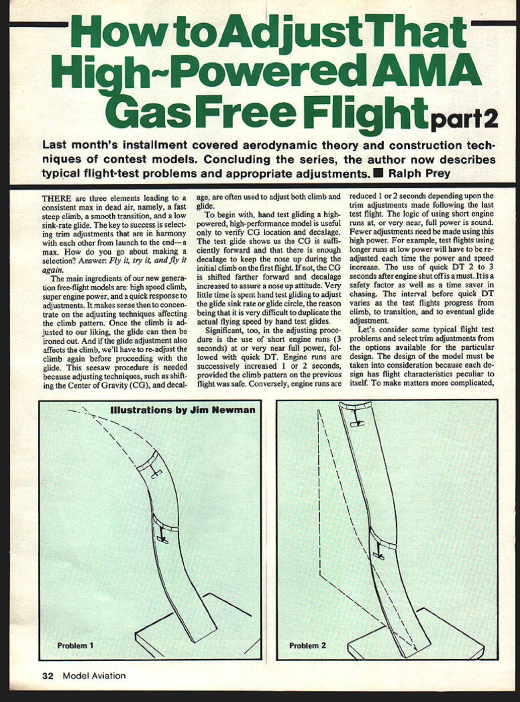
Problem 1
Model goes into a steep right climb for 6–8 seconds, after which the right wing starts to raise and the turn begins to straighten toward the left. The climb attitude remains steep. Any further engine run would result in a climbing left roll. The problem involves the longitudinal and vertical axes.
- For pylon designs with wash-in on the right main wing panel (using right or left thrust): the raising of the right wing after 6–8 seconds is due to wash-in becoming more effective with speed and resulting in a left roll. Thrust effectiveness decreases with speed and is not the cause. To reduce the left roll, decrease the wash-in slightly. Make no other adjustments.
- For pylon designs with wash-out on the left main wing panel (using right thrust), and for designs that also use left fin or rudder offset with wash-out: the wash-out of the left panel becomes more effective with speed, raising the right wing as speed builds and rolling the model to the left. Fin and rudder tab effectiveness increase with speed. Options: reduce left rudder tab or reduce wash-out to reduce left roll. Increasing right thrust is a last-chance option.
- For pylon designs with no wing wash-in or wash-out that use left fin/rudder offset with thrust offset: the right-wing rise after 6–8 seconds is due to increased effectiveness of the left fin/rudder offset with speed. Thrust loses effectiveness with speed; decrease left fin/rudder offset and make no other adjustments.
- For high-thrust-line designs: the model may be climbing in the wrong direction. Check carefully for wing warps. There should be no wash-in in the left main panel or wash-out in the right main panel. Also check the thrust offset: there should be no right thrust. Use a left rudder-tab offset to control the model into a climbing left turn.
Problem 2
Model goes into a steep right climb for 9–10 seconds; the climb angle increases slightly, the turn starts to straighten toward the left, and the right wing begins to raise. With a full 12-second engine run the wing would be almost level with the horizon at a steep climb angle. The problem involves the longitudinal and vertical axes.
- For pylon designs with wash-in on the right main wing panel (using right or left thrust): the wash-in is still the reason for the late changes. Don't change the wash-in. Instead, add a very small amount of right rudder-tab offset. The right tab will become effective as speed builds (6–8 seconds) and will keep the model grooving by overpowering the wash-in in the full run. If the model is set to glide right (the preferred and safest direction), the right tab will help the transition by holding the model in a right turn. As speed decreases, the right tab loses effectiveness and the stabilizer tilt then takes over for the glide turn. Make no other adjustments. If the model is set to glide left, a small right rudder tab should not adversely affect the transition or glide; if it does, do not use the right-tab offset and instead reduce the wash-in.
- A traditional right climb, left glide pattern when using stabilizer tilt and wash-in on the right or wash-out on the left can result in the model diving in the glide, particularly if glide speed increases due to a gust. The increased speed increases the effectiveness of the wash-in/wash-out, resulting in a left rolling dive.
- For pylon designs with wash-out on the left main wing panel that use right thrust (and designs also using left rudder): the wash-out and/or left rudder remain the reasons for the late changes. It may also loop, caused by either a forward CG location or too much decalage, or both. Check the CG: if the CG is farther aft than it should be, move nose weight forward. If the decalage is excessive, reduce decalage. If the model dives, check for an aft CG or too little decalage and correct by moving the CG forward or increasing decalage. Recheck with a short, near-full-power run and a quick DT.
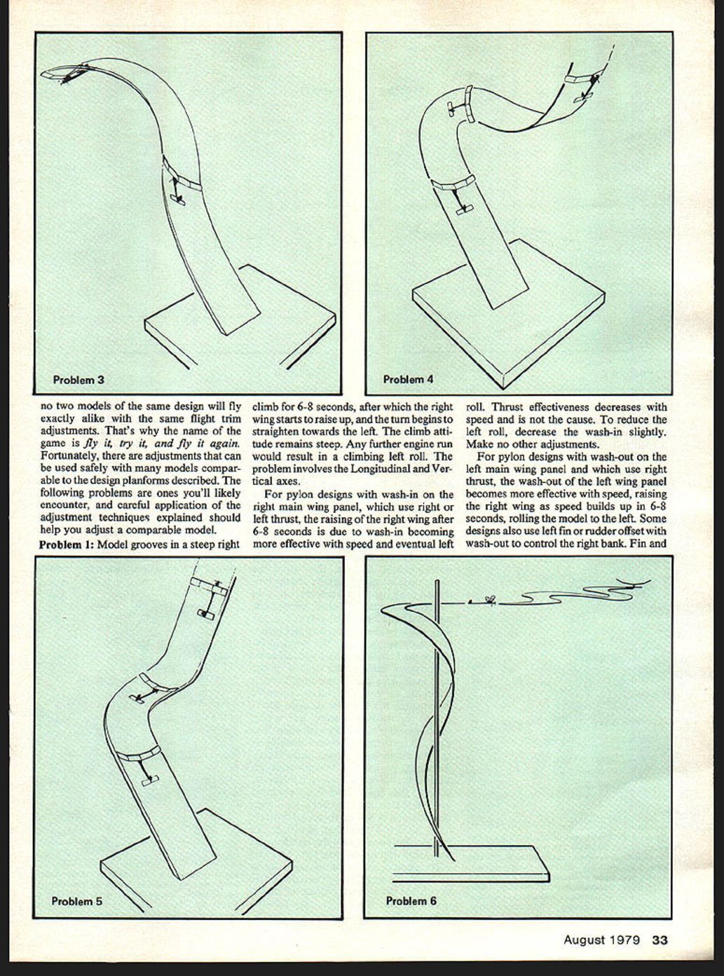
Problem 5
Model starts a steep right climb, and after 1–2 seconds dips to the right, building up speed, then resumes a steep right climb. The problem involves the vertical axis.
- The dip can be due to the angle and direction of launch. If launched near vertical, or steeper than the normal climb angle, it will dip right after launch. Also, if launched crosswind so the wind strikes the left half of the wing more than the right (which would occur when the nose is banked and pointed to the right of the wind), the model will dip. Launch technique is important: point the model up at about an 80-degree angle and almost dead center into the wind with a slight right bank. Never launch a pylon model to the left of the wind, or more than a few degrees to the right of the wind. Never bank the model more than a few degrees to the right while launching.
- If the launch was correct, the dip right after launch is due to the thrust offset:
- For pylon designs with wash-in on the right main wing panel (using right or left thrust): check thrust offset. If right thrust is used, reduce the right thrust. If left thrust is used, increase the left thrust.
- For pylon designs with wash-out on the left main wing panel that use right thrust: reduce the right thrust.
- For pylon designs with no wash-in or wash-out that use left vertical fin or rudder offset (with or without thrust offset): crank in left thrust.
- For high-thrust-line designs: watch the launch closely, or add more left rudder-tab offset. You never want to climb right.
Problem 6
Model completes the full engine run, the transition is satisfactory, and the glide starts turning to the desired glide direction but then slows upwind and starts turning the opposite direction. It speeds up downwind and again starts to change turn direction, repeating the wandering. The problem involves the longitudinal axis.
- For pylon designs with wash-in on the right main wing panel and stabilizer tilt for a left turn: the wash-in is too much, causing drag. The drag increases upwind as the model slows, turning the model to the right. As speed builds downwind, drag decreases and lift increases, turning the model to the left. The process repeats.
- Options:
- Change the glide circle from left to right. Depending on stabilizer size and tilt, the model may glide right without changing the wash-in.
- If you want to stay with the left glide, reduce the wash-in and readjust the climb. (Increasing stabilizer tilt will cause instability and may cause a left dive if speed increases in the glide.)
- With reduced wash-in the model will bank and turn tighter to the right during climb. Use left vertical fin or rudder tab to increase effectiveness as speed increases.
- For pylon designs that have no wing wash-in or wash-out but use left fin/rudder offset and thrust offset: the right wing may rise after 6–8 seconds due to increased effectiveness of the left fin/rudder as speed increases. Thrust loses relative effectiveness as speed increases, which can decrease the corrective effect of the left fin/rudder offset. In such cases, make no other adjustments. The offset will help the transition by initiating a left turn as soon as the engine cuts and will assist the stabilizer tilt for the left glide. If the glide circle was originally set for a right glide, increase the stabilizer tilt. If tilt does not make the model turn right, it may be necessary to decrease the wash-in. If wash-in is reduced, readjust the climb using right rudder as required to bank right in the climb.
- For pylon designs with wash-out on the left main wing panel and stabilizer tilt for a left glide turn: the wash-out becomes effective upwind due to decreased speed. The stabilizer tilt may be trying to overpower the wing forces but cannot quite make it. Increase stabilizer tilt for more left glide turn, but be careful not to use too much tilt, which could cause instability and a left dive when upset by a gust.
- For pylon designs with no wash-in or wash-out that use left vertical fin or rudder offset, and for high-thrust-line designs: the stabilizer tilt may not be enough to keep the model turning as intended. Also, left rudder-tab offset may be affecting the turn as speed increases downwind, causing some wandering. Increase the tilt for more left or right turn, as needed.
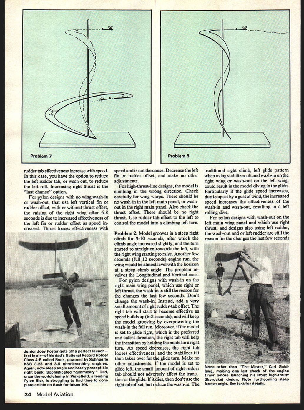
Problem 7
Model completes the full engine run at a shallower angle than you like. It makes about 1/2 to 3/4 turn to the right during the full 12 seconds, but you want at least 1 to 1 1/4 turns. The transition is good, but the glide is too fast and nose-down. The problem involves the lateral axis.
- For pylon models, this is an overall nose-down tendency caused by insufficient decalage. Increasing decalage (by decreasing the positive angle of incidence of the stabilizer) will raise the nose in the climb and in the glide. When decalage is increased it also increases the tendency of the model to turn right in the climb, and conversely decreases the turn in the glide.
- Therefore: decreasing the decalage will increase the right turn in the climb to the desired 1–1 1/4 turns and will slow the sink rate in the glide. Adjust glide turn with stabilizer tilt.
Problem 8
Model grooves in a steep right climb, transition is perfect, glide turn is perfect, but there is an occasional slight stall. The problem involves the lateral axis.
- For most pylon and high-thrust designs, the cure is simple: add a little nose weight to reduce the stall. Many resist adding weight, but the weight will help the model penetrate upwind and improve the glide sink rate.
Problem 9
Model grooves in a steeper climb than you want, transition is good, and the glide is perfect. On a calm day the climb pattern would be acceptable, but the least increase in wind could make the model loop in the climb. The problem involves the lateral axis.
- For most pylon and high-thrust designs: reduce the decalage to flatten the climb, and add weight to the tail to adjust the glide. The decalage can be reduced by shimming under the leading edge of the stabilizer, which will bring the nose down in the climb. Reduced decalage will speed up the glide; however, added weight to the tail will restore a perfect glide. The few grams added to the tail to get the glide adjusted perfectly won't add enough to wing loading to change the glide significantly.
Do's and Don'ts while making adjustments
- When adding incidence to the wing or stabilizer, don't use balsa shims. Balsa compresses and will change the adjustment. Use 1/64", 1/32", or 1/16" plywood shims. If shims less than 1/64" are needed, use brass shims. Any auto-parts store has brass shim stock in various sizes.
- If the vertical fin is to be used for offset instead of a rudder tab, be sure to re-key the stabilizer when the fin is on the stabilizer. Again, use hard woods.
- If a metal engine mount is used, be sure that side thrust can be added without also adding down thrust. For example, when adding side thrust to a mount with only three mounting holes, down thrust is also added, which is not needed. Re-drill the mount so that there are four mounting holes, and don't use the original center bottom hole for mounting. The four holes can be spaced so that when side thrust is needed you don't get down thrust.
- Use metal shims for all engine thrust adjustments when using metal mounts. To keep the shim from pressing into the plywood firewall, use a .020" aluminum spacer against the firewall and the metal mount. Insert the metal shim between the aluminum spacer and the mount.
- Check the DT line for tension. Too much tension can bow the fuselage, changing either the decalage or the vertical fin/rudder offset.
One final thought: stand by your own decisions about adjustments. It's your model and your decision; don't let a bystander con you into other adjustments against your judgment. You've built into your design things the bystander doesn't know about. Even if you make a mistake, let it be your decision — you'll learn more that way. I hope the information in this series will help you make the right decisions and continuously max in dead air.
Transcribed from original scans by AI. Minor OCR errors may remain.

