
How To Do It: Economical
George Kyer
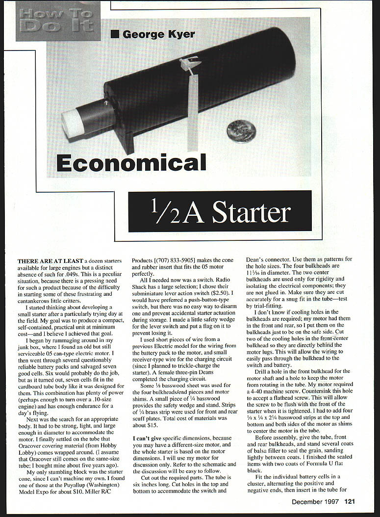
1/2A Starter
There are at least a dozen starters available for large engines but a distinct absence of such for .049s. This is a peculiar situation, because there is a pressing need for such a product because of the difficulty in starting some of these frustrating and cantankerous little critters.
I started thinking about developing a small starter after a particularly trying day at the field. My goal was to produce a compact, self-contained, practical unit at minimum cost — and I believe I achieved that goal.
I began by rummaging around in my junk box, where I found an old but still serviceable .05 can-type electric motor. I then went through several questionably reliable battery packs and salvaged seven good cells. Six would probably do the job, but as it turned out, seven cells fit in the cardboard tube body like it was designed for them. This combination has plenty of power (perhaps enough to turn over a .10-size engine) and has enough endurance for a day's flying.
Next was the search for an appropriate body. It had to be strong, light, and large enough in diameter to accommodate the motor. I finally settled on the tube that Oracover covering material (from Hobby Lobby) comes wrapped around. (I assume that Oracover still comes on the same-size tube; I bought mine about five years ago.)
My only stumbling block was the starter cone, since I can't machine my own. I found one at the Puyallup (Washington) Model Expo for about $10. Miller R/C Products ((707) 833-5905) makes the cone and rubber insert that fits the .05 motor perfectly.
All I needed now was a switch. Radio Shack has a large selection; I chose their subminiature lever-action switch ($2.50). I would have preferred a push-button-type switch, but there was no easy way to disarm one and prevent accidental starter actuation during storage. I made a little safety wedge for the lever switch and put a flag on it so it wouldn't get lost.
I used short pieces of wire from the previous electric model for the wiring from the battery pack to the motor, and small receiver-type wire for the charging circuit (since I planned to trickle-charge the starter). A female three-pin Deans connector completed the charging circuit.
Some 1/8" basswood sheet was used for the four bulkheads/end pieces and motor shims. A small piece of 1/4" basswood provides the safety wedge and stand. Strips of 1/4" brass strip were used for front and rear scuff plates. Total cost of materials was about $15.
I can't give specific dimensions, because you may have a different-size motor, and the whole starter is based on the motor dimensions. I will use my motor for discussion only. Refer to the schematic and the discussion will be easy to follow.
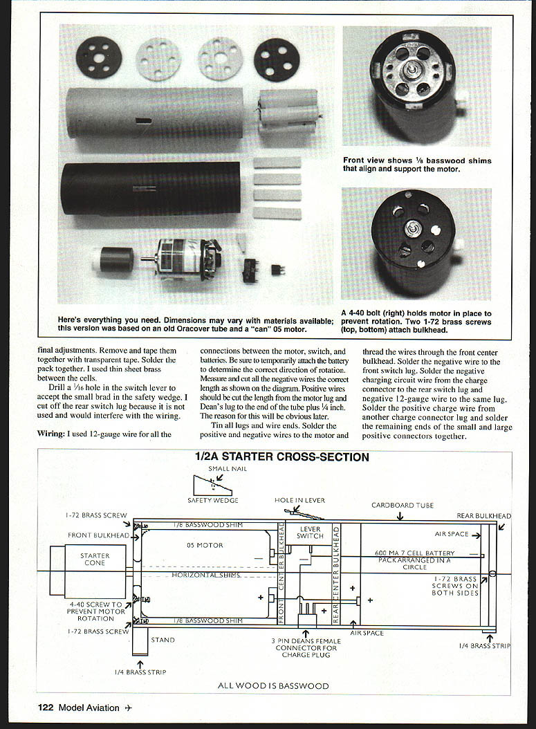
Cut out the required parts. The tube is six inches long. Cut holes in the top and bottom to accommodate the switch and Deans connector. Use them as patterns for the hole sizes. The four bulkheads are 1 11/16" in diameter. The two center bulkheads are used only for rigidity and isolating the electrical components; they are not glued in. Make sure they are cut accurately for a snug fit in the tube — test by trial-fitting.
I don't know if cooling holes in the bulkheads are required; my motor had them in the front and rear, so I put them on the bulkheads just to be on the safe side. Cut two of the cooling holes in the front-center bulkhead; those are directly behind the motor lugs. This will allow the wiring to pass through easily from the bulkhead to the switch and battery.
Drill a hole in the front bulkhead for the motor shaft and a hole to keep the motor from rotating in the tube. My motor required a 4-40 machine screw. Countersink this hole to accept a flathead screw. This will allow the screw to be flush with the front of the starter when it is tightened. I had to add four 1/2" x 1/4" x 2-1/2" basswood strips at the top and bottom and both sides of the motor as shims to center the motor in the tube.
Before assembly, give the tube, front and rear bulkheads, and stand several coats of balsa filler to seal the grain, sanding lightly between coats. I finished the sealed items with two coats of Formula U flat black.
Fit the individual battery cells in a cluster, alternating the positive and negative ends, then insert in the tube for final adjustments. Remove the tape and solder the pack together; I used a thin sheet of brass between the cells.
Drill a 6/64" hole in the switch lever to accept a small brad for the safety wedge. Cut off the rear switch lug because it would interfere with the wiring.
Wiring:
- I used 12-gauge wire for the connections between the motor and the batteries. Be sure to temporarily attach the battery to determine the correct direction of rotation.
- Measure and cut the negative wire to the correct length as shown in the diagram. Positive wires should be cut to length from the motor lug to the Deans lug at the end of the tube — the reason will be obvious later.
- Tin the lug and wire ends. Solder the positive and negative wires to the motor, and thread the wires through the front-center bulkhead.
- Solder the negative wire to the front switch lug. Solder the negative charging-circuit wire to the rear switch lug. Solder the negative 12-gauge wire to the same lug.
- Solder the positive charge wire to the other charge-connector lug. Solder the remaining ends of the small and large positive connectors together.
No additional article text appears on this page — it contains photographs, captions, and the 1/2A starter cross-section diagram that complete the "How To Do It: Economical" article.
Now for the fun. Slip the whole mess into the tube from the front with the front bulkhead mounted to the motor. Push the assembly into the tube until the front bulkhead is flush with the tube front. With long-nose pliers or a hemostat, maneuver the switch and Deans connector into their respective holes until the top of the switch/connector is level with the top/bottom of the tube. Use thin cyanoacrylate (CyA) glue to secure in place.
Remove the front bulkhead and insert the four basswood shims at 90° angles around the motor. Recheck that the front bulkhead is still flush with the tube front, then remove and secure the shims in place with thin CyA.
Run the remaining wires through the rear center bulkhead and slide the bulkhead against the rear of the switch. Run the negative wires through a space between the batteries to the rear battery terminal. Solder the positive leads to the front battery terminal and push the battery pack into the tube. Solder the negative wires to the negative terminal and put the rear bulkhead in place. Use a pin vise to drill small holes in the rear edge of the tube and bulkhead to secure in place. I drilled holes through the front bulkhead into the shims to secure it. #00 brass screws are used in the front and rear.
Add the stand to the front end. I used GOO for this and also to secure the scuff plates. Put a small brad in the safety wedge and cut off the head. Your starter is complete and ready for use.
George Kyer 10824 31st Ave. NE Carnation, WA 98014
Transcribed from original scans by AI. Minor OCR errors may remain.

