
How To Do It: Large Pack Slow Charger
Bob Kopski
The rapidly growing interest in electric-powered aeromodels brings diversity of model size and type, as well as increased use of wide-ranging cell counts in the motor batteries. It is common to find batteries ranging from a few cells to 20 cells or more on the flightline of any meet. It is also common to find high-tech, high-capability fast chargers on the flightline. What seems to be missing are reliable "slow" chargers for the higher-cell-count packs.
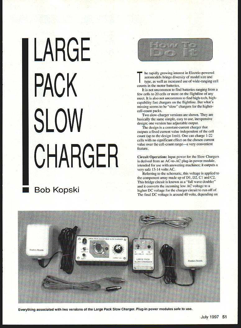
Two slow-charger versions are shown. They are basically the same simple, easy-to-use, inexpensive design; one version has adjustable output. The design is a constant-current charger that outputs a fixed current value independent of the cell count (up to the design limit). One can charge 1–22 cells with no significant effect on the chosen current value over that range — a very convenient feature.
Circuit Operation
Input power for the slow chargers is derived from an AC-to-AC plug-in power module, intended for use with answering machines; it outputs a very safe 13–14 volts AC.
Referring to the schematic, this voltage is applied to the component array made up of D1, D2, C1 and C2. This bridge circuit is known as a "full-wave doubler" and it converts the incoming low AC voltage to a higher DC voltage for the charger circuit to run off of. The final DC voltage is around 40 volts, depending on the exact line voltage in your location. As shown, the circuit also has a voltage tap between C1 and C2 of about 20 volts. This tap has an important use (see Range switch and heat below).
The remainder of the slow charger circuit consists primarily of transistor Q1 and its biasing. Q1 is configured as an electronic current source wherein the "load" (battery being charged) is placed in the collector circuit. The battery is connected between the transistor collector and the switch-selected positive voltage coming from either C1 (≈20 V) or C2 (≈40 V).
Charging current and R2
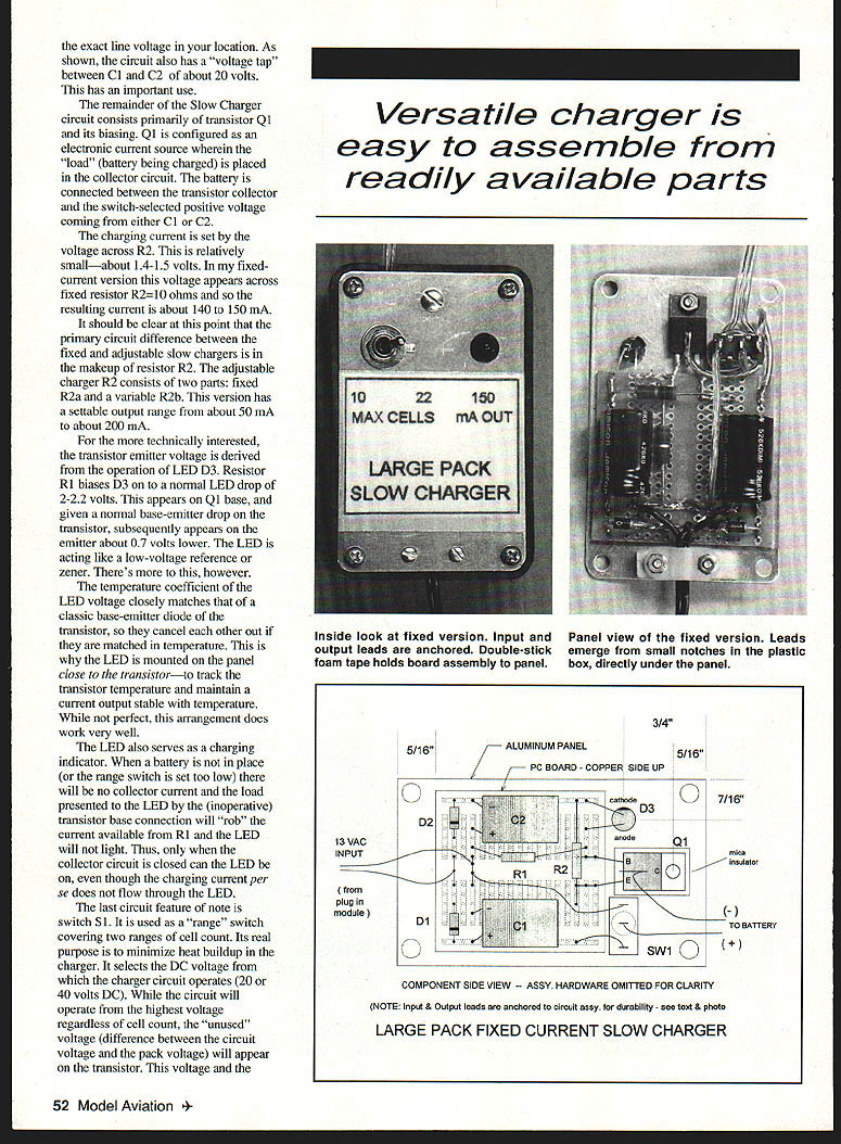
The charging current is set by the voltage across R2. This is relatively small — about 1.4–1.5 volts. In the fixed-current version this voltage appears across fixed resistor R2 = 10 ohms and so the resulting current is about 140–150 mA.
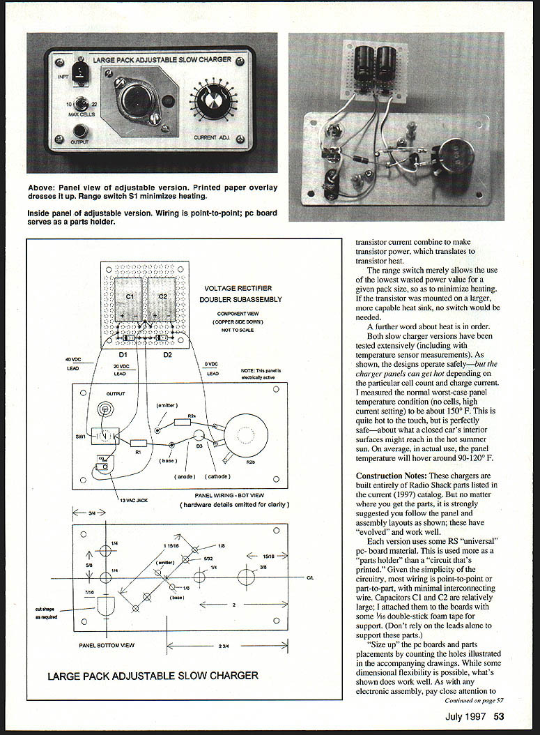
The primary circuit difference between the fixed and adjustable slow chargers is in the makeup of resistor R2. The adjustable charger R2 consists of two parts: fixed R2a and variable R2b. This version has a settable output range from about 50 mA to about 200 mA.
Temperature compensation and the LED
For the more technically interested, the transistor emitter voltage is derived from the operation of LED D3. Resistor R1 biases D3 on to a normal LED drop of about 2.2 volts. This appears on Q1 base, and given a normal base-emitter drop on the transistor, subsequently appears on the emitter about 0.7 volts lower. The LED is acting like a low-voltage reference or zener.
The temperature coefficient of the LED voltage closely matches that of a transistor base-emitter diode, so they cancel each other out if they are matched in temperature. This is why the LED is mounted on the panel close to the transistor — to track the transistor temperature and maintain a current output stable with temperature. While not perfect, this arrangement does work very well.
The LED also serves as a charging indicator. When a battery is not in place (or the range switch is set too low), there will be no collector current and the load presented to the LED by the (inoperative) transistor base connection will "rob" the current available from R1 and the LED will not light. Thus, only when the collector circuit is closed can the LED be on, even though the charging current itself does not flow through the LED.
Range switch and heat
The last circuit feature of note is switch S1. It is used as a range switch covering two ranges of cell count. Its real purpose is to minimize heat buildup in the charger. It selects the DC voltage from which the charger circuit operates (about 20 V or about 40 V). While the circuit will operate from the highest voltage regardless of cell count, the "unused" voltage (the difference between the circuit voltage and the pack voltage) will appear on the transistor. This voltage and the transistor current combine to make transistor power, which translates to transistor heat.
The range switch merely allows the use of the lowest wasted power value for a given pack size, so as to minimize heating. If the transistor were mounted on a larger, more capable heatsink, no switch would be needed.
A further word about heat: both slow charger versions have been tested extensively (including with temperature sensor measurements). As shown, the designs operate safely — but the charger panels can get hot depending on the particular cell count and charge current. The measured worst-case panel temperature condition (no cells, high current setting) was about 150°F. This is quite hot to the touch, but is perfectly safe — about what a closed car's interior surfaces might reach in hot summer sun. On average, in actual use, the panel temperature will hover around 90–120°F.
Construction Notes
These chargers are built entirely of Radio Shack parts listed in the current (1997) catalog. But no matter where you get the parts, it is strongly suggested you follow the panel and assembly layouts as shown; these have "evolved" and work well.
Each version uses some RS "universal" PC-board material. This is used more as a "parts holder" than as a printed circuit. Given the simplicity of the circuitry, most wiring is point-to-point or part-to-part, with minimal interconnecting wire. Capacitors C1 and C2 are relatively large; attach them to the boards with some 1/16" double-stick foam tape for support (do not rely on the leads alone to support these parts).
Size up the PC boards and parts placements by counting the holes illustrated in the drawings. While some dimensional flexibility is possible, what's shown does work well. As with any electronic assembly, pay close attention to parts polarity and wiring completeness and accuracy. Note that LEDs are polarized. The cathode (negative) lead can be identified with a small flat visible on the base of the LED.
Fixed-current version
- Transistor Q1 is mechanically mounted and electrically isolated by the mounting hardware. The thermal conduction and electrical insulation qualities of the mounting kit are only good when used on a flat panel surface free of burrs. Do clean panel work.
- The component PC-board subassembly is held to the aluminum panel with 1/16" double-stick foam tape. Be sure that no component leads protrude through the board holes and contact the panel. The PC board lands are meant more as anchor points than as printed circuitry.
- Assemble, carefully inspect and clean the PC board, then position and stick it to the panel where shown. Mount Q1 on the panel. The transistor base and emitter leads lie flat on, and are soldered to, the three PC lands each. The middle (collector) lead is bent back up over the transistor body and serves as a tie point for the negative output wire.
- The positive output wire comes from S1 middle post, and both output wires are strain-relieved by wrapping them around the body of S1.
- Cut off the connector that comes on the power module output lead and solder the wires directly to the appropriate PC lands. Anchor the wire pair to the panel assembly with a 1/8" plastic landing-gear strap, wood spacer block, and 2-56 × 1/2 hardware. The spacer measures 1/4" × 3/8" × 1".
- The input and output leads emerge from small notches cut in the plastic boxes just under the aluminum panels.
Adjustable version
- Transistor Q1 is the same electrical part as used in the fixed-current version but is mechanically different. The case of Q1 is the collector connection and is hard-mounted to the panel. Thus the panel is electrically equal to the negative end of the motor battery pack. This approach is used because this Q1 must handle and dissipate more power than in the fixed-current version.
- A small amount of properly applied thermal grease between the transistor and panel is advantageous but not necessary. Be sure that Q1 is tightly mounted to a flat, undistorted panel surface to maximize thermal conductivity.
- The input and output lead attachment in this version is connectorized. The connectors provide internal wiring tie points. You may attach the leads permanently if desired.
Operating Notes — Both Versions
With respect to R2 (or R2a + R2b), some selection effort may be needed to suit your particular application (and because of limitations of Radio Shack resistor inventory). The fixed-current version outputs 140–150 mA and is suitable for packs having 1.2, 1.4, and 1.7 Ah cells.
You can lower the current in the non-adjustable version with a larger value of R2, but R2 choices may be limited. To get around this, you can series-parallel available resistors to obtain a desired value. If this is too much for you, get the assistance of your local electronics hobby expert or find a better parts source.
"Resistor fudging" may be used in the adjustable version too. R2a is made up of two 1/4-watt 10-ohm resistors in series and a third one wired across the two. This three-resistor combination calculates to 6.7 ohms. It's what was needed so that when used electrically in series with variable resistor R2b the current adjustment range covered about 50–200 mA.
There are several variables that collectively affect the final current (or current range) values, including the exact LED voltage, transistor base-emitter drop, and resistor tolerances. Thus, having some flexibility in R2 (or R2a) is useful. In any case, do not exceed 150 mA in the fixed-current version and 200 mA in the adjustable one.
Checkout — Both Versions
All that's needed is a multimeter, some test leads, and a temporary load resistor.
- With the ohmmeter function, measure between the (fixed-current version) panel and the transistor collector. This should be an open circuit.
- Verify "open circuit" between the panel and other random circuit points — there should be no contact between any circuit node and the panel.
- For the adjustable version, there should be solid contact (0 ohms) between the panel and the collector — it is made that way.
- With no load connected to the charger output, connect a DC voltmeter between the 0 and 40 volt points (bottom of C2 to the top of C1) and plug in the power module. The LED should not be lit. You should read close to 40 volts DC.
- Confirm the voltage across C2; it should be close to 20 volts. Unplug the module.
- (Note: the voltage readings depend on the exact AC line voltage where you perform this test.)
- Temporarily connect the 100-ohm test load resistor to the charger output and place a DC voltmeter across the resistor. Plug in the module. The LED should now light.
- For the fixed-current version, the resistor voltage should be around 14–15 volts. If you choose a lower current value, the resistor voltage will vary accordingly. The voltage reading should remain close to the same value with the range switch in either position. LED brightness should also be constant.
- For the adjustable version, the resistor voltage should vary from about 5–20 volts over the adjustment range. You may need to adjust R2a to obtain the full range. The 20-volt level may only be achieved with the range switch set to the "10–22" position.
- If all checks out, unplug the module, remove the test resistor, and connect a candidate battery in its place to charge. Temporarily connect an ammeter in series with the circuit. Choose an ammeter range to allow verification of the chosen charge-current levels (either fixed or variable). Plug in the module and confirm the correct current level.
- If possible, substitute packs of differing cell count during this test and verify the constancy of the chosen current level.
Try charging some packs overnight — you should be pleased with the results.
Bob Kopski 25 West End Dr. Lansdale, PA 19446
Transcribed from original scans by AI. Minor OCR errors may remain.

