
How to Make Laminated Prop Blades
Less work, and cheaper, than carving rubber-model props, these sturdy blades will spare you the soul-shattering experience of 'self-destructing' props when striking the ground. • Jim O'Reilly
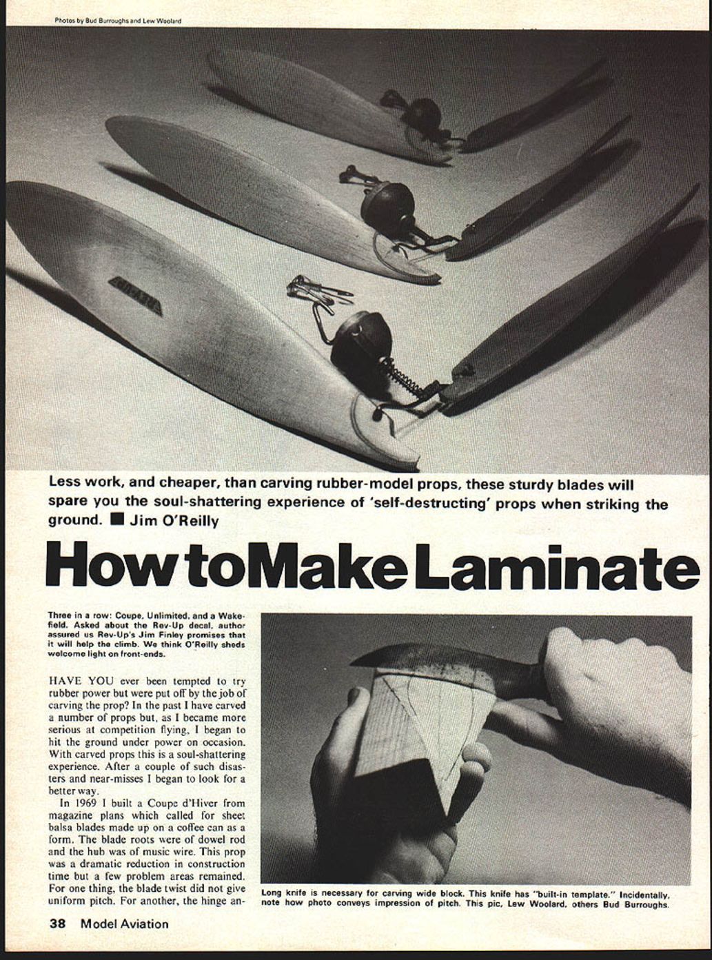
Three in a row: Coupe, Unlimited, and a Wakefield. Asked about the Rev-Up decal, author assured us Rev-Up's Jim Finley promises that it will help the climb. We think O'Reilly sheds welcome light on front-ends.
HAVE YOU ever been tempted to try rubber power but were put off by the job of carving the prop? In the past I have carved a number of props but, as I became more serious at competition flying, I began to hit the ground under power on occasion. With carved props this is a soul-shattering experience. After a couple of such disasters and near-misses I began to look for a better way.
In 1969 I built a Coupe d'Hiver from magazine plans which called for sheet balsa blades made up on a coffee can as a form. The blade roots were of dowel rod and the hub was of music wire. This prop was a dramatic reduction in construction time but a few problem areas remained. For one thing, the blade twist did not give uniform pitch. For another, the hinge and music-wire hub, hinge holes through the blade, were hard to make accurately. In theory one could replace blades; in fact there was no way to make identical blades.
After a couple years I evolved a system that answers these objections. Part of the system was borrowed from buddies, part stumbled onto, and part I invented. The system requires less work than carving and is far cheaper. Replacement blades are truly possible. The total front-end assembly is generally lighter than the carved variety. A final bonus: you may discover that the prop, motor and airframe show new pride of workmanship — mismatched pieces may be possible to salvage by repitching a prop or bending a wire hub. Try a wooden hub.
As for limitations, some rubber fliers feel formed blades will not hold their shape. This tends to be true of non-laminated blades; it is certainly not true of laminated blades. Some people shy away from wire hubs because they are difficult to build accurately. The answer is a drilled-hole form block that serves as a drill jig for the prop blade and also as an alignment jig for forming the wire hub.
Carving block: form block is its accurately drilled hole hinge line. What sets the system apart is the block. The block may be carved from pine, fir, or spruce, or may be poured of polyester auto-body putty or plaster. Dave Linstrum has published Coupe d'Hiver built-up form blocks made of balsa sheet strips. Actually, a built-up block is adequate for forming blades.
Long knife is necessary for carving wide block. This knife has a "built-in template." Incidentally, note how photo conveys impression of pitch. This pic, Lew Woolard; others, Bud Burroughs. Holes on the wire hub and the hinge holes through the blade were a struggle to make accurately. In theory, I could replace blades but, in fact, I had no way to make them identical.
After a couple of years I evolved a system which answers most of these objections. Part of the system was borrowed from my buddies, part was stumbled onto, and part was invented here. The system is not only less work than carving but far cheaper. Replacement blades are truly possible. The total front end assembly is generally lighter than the carved variety. And a final bonus: If you discover that the prop, motor, and airframe, on your new pride and joy are mismatched, it may be possible to salvage it by repitching the prop or by bending the wire hub. Try that on a wooden hub! As to limitations, I am not aware of any. Some rubber fliers feel that formed blades will not hold their shape. This tends to be true of non-laminated blades but is certainly not true of laminated blades. Some people shy away from wire hubs as difficult to build accurately. The answer here is the drilled hole in the form block. It serves as a drill jig for the prop blade and also as an alignment jig for forming the wire hub.
Carving the Block: The form block with its accurately drilled hole at the hinge line is what sets this system apart. The block may be carved from pine, fir or spruce, or it may be poured from polyester auto body putty or from plaster. Dave Linstrum has published a Coupe d’Hiver with a built-up form block made from balsa sheet and strip. Actually a built-up block, while adequate for forming blades, may not be rugged enough to use as a jig for the hub unless it is reinforced by pouring it full of resin. The point here is that you needn’t let the carving throw you.
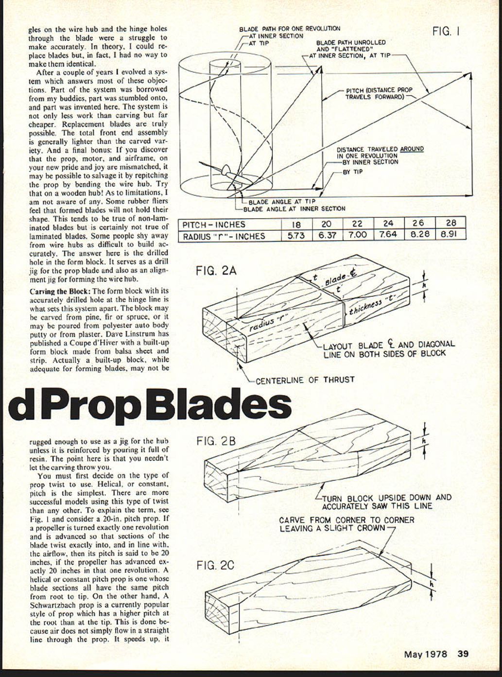
You must first decide on the type of prop twist to use. Helical, or constant, pitch is the simplest. There are more successful models using this type of twist than any other. To explain the term, see Fig. 1 and consider a 20-in. pitch prop. If a propeller is turned exactly one revolution and is advanced so that sections of the blade twist exactly into, and in line with, the airflow, then its pitch is said to be 20 inches. If the propeller has advanced exactly 20 inches in that one revolution, a helical or constant pitch prop is one whose blade sections all have the same pitch from root to tip. On the other hand, a Schwartzbach prop is a currently popular style of prop which has a higher pitch at the root than at the tip. This is done because air does not simply flow in a straight line through the prop. It speeds up, it twists, and it flows inward as it passes through the prop disc.
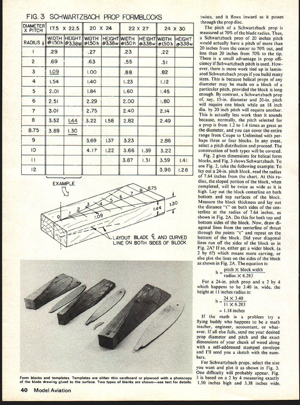
The pitch of a Schwartzbach prop is measured at 70% of the blade radius. Thus, a Schwartzbach prop of 20 inches pitch would actually have a pitch of more than 20 inches from the center to 70% out, and less than 20 inches from 70% to the tip. There is a small advantage in prop efficiency if Schwartzbach pitch is used. However, there is more work tied up in laminated Schwartzbach props if you build many sizes. This is because helical props of any diameter may be made on a block of a particular pitch, provided the block is long enough. By contrast, a Schwartzbach prop of, say, 15-in. diameter and 20-in. pitch will require one block while an 18 inch dia. by 20 inch pitch will require another. This is actually less work than it sounds because, normally, the pitch selected for a prop is from 1.2 to 1.4 times as great as the diameter, and you can cover the entire range from Coupe to Unlimited with perhaps three or four blocks. In any event, select a pitch distribution and proceed. The construction of both types will be covered.
Fig. 2 gives dimensions for helical form blocks, and Fig. 3 shows Schwartzbach. To use Fig. 2, take the following example: To lay out a 24-in. pitch block, read the radius of 7.64 inches from the chart. At this radius, the sloped portion of the block, when completed, will be twice as wide as it is high. Lay out the block centerline on both bottom and top surfaces of the block. Measure the block thickness and lay out the distance "t" on both sides of the centerline at the radius of 7.64 inches, as shown in Fig. 2A. Do this for both top and bottom sides of the block. Now, draw diagonal lines from the centerline of thrust through the points "t" and repeat on the bottom of the block. Did your diagonal lines run off the sides of the block as in Fig. 2A? If so, either get a wider block, (a 2 by 6?) which means more carving, or else plot the lines on the sides of the block as shown in Fig. 2A. The equation is:
h = pitch X block width radius X 6.283
For a 24-in. pitch prop and a 2 by 4 which happens to be 3.40 in. wide, the height at 11 inches radius is:
h = 24 X 3.40 11 X 6.283 = 1.18 inches
If the math is a problem try a flying buddy who happens to be a math teacher, engineer, accountant, or whatever. If all else fails, send me your desired prop diameter and pitch and the exact dimensions of your chunk of wood along with a self-addressed stamped envelope and I'll send you a sketch with the numbers.
For Schwartzbach props, select the size you want and plot it as shown in Fig. 3. One difficulty will probably appear. Fig. 3 is based on a 2 by 4 measuring exactly 1.50 inches high and 3.38 inches wide. Your 2 by 4 will likely be slightly different in width, height, or both. Simply multiply the numbers in the width column by the ratio of your block height to 1.50 inches. For example, if your block is actually 1.48 inches high, divide 1.48 by 1.50 to obtain .99. Multiply all numbers in the width column by .99. In the same way, if your block is not exactly 3.38 wide, multiply numbers in the height column by the ratio of your block width to 3.38. If you are as close in width as .01 or .02 inches you can ignore this step with little difference. Be careful not to do it backwards. If your block is not as high or wide, you will be multiplying by a number like .98 or .99. If your block is bigger rather than smaller, the multiplier will be like 1.02 or 1.04.
When either type of block has been plotted, saw it as in Fig. 2B. Since the blade on a light hobby saw will wander badly, turn the block upside down to saw it because it's the bottom line which needs to be accurate. Finally, carve the block as in Fig. 2C. I use a sharp hunting knife with a concave back and use the back of the blade to gage when carving is complete as shown in the photo. I leave the slight crown only because it's less work than carving down to a straight line, not because I want blade camber.
There are two schools of thought on blade camber. There is not enough evidence to be conclusive, but I believe that flat-bottom blades will outperform under-cambered blades. Ron Roberti of Norman, Oklahoma, is of the under-camber school of thought and Ron laminates blades. He uses a narrow strip of 1/32 balsa glued to the face of the block to form camber into the blade. After carving you have the option of sanding and finishing the form block, but these extra steps are not necessary. You can see in the photos that my blocks are nearly "as carved" with little sanding and no filling or painting.
With the carving and sanding all done the hole for the hinge line can be drilled. I use a skewed hinge line so that the blade rolls as it folds and ends up more or less parallel to the fuselage. Theoretically, the skew angle should be half of the angle at the widest part of the blade. I simply use 10° for a skew angle and it's always within a degree or two. How far the hinge line is located from the prop centerline is also important. Too close in and the blade will fold back and hit the fuselage before it reaches a streamlined position. Too far out and a gap will remain between the prop and the fuselage. (This is not necessarily bad; some fliers feel this gives lower drag when folded.) To be safe, locate the hinge points a half-inch further from the prop centerline than half the width of the fuselage.
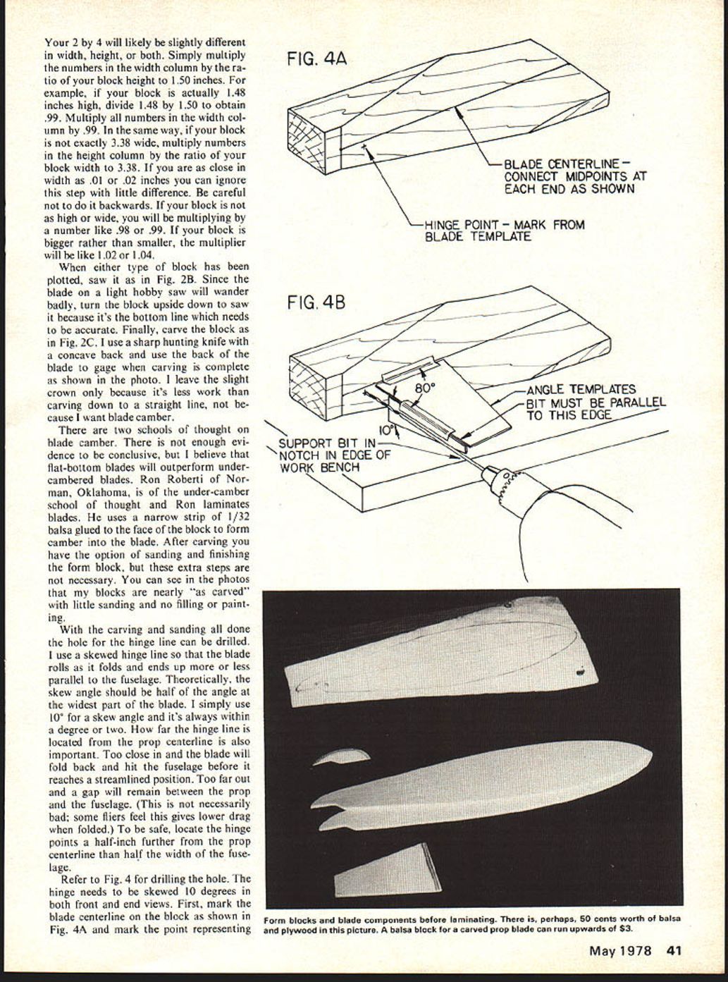
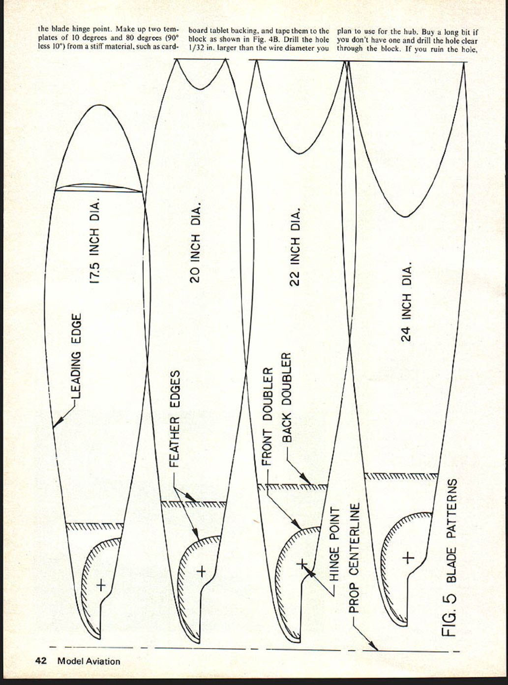
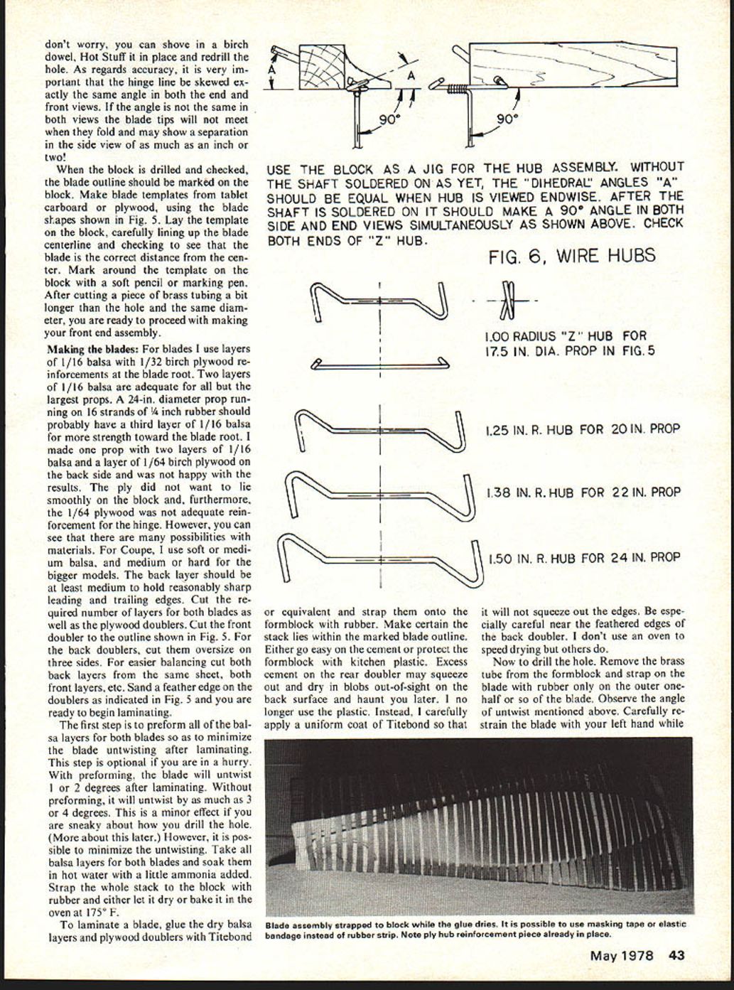
Refer to Fig. 4 for drilling the hole. The hinge needs to be skewed 10 degrees in both front and end views. First, mark the blade centerline on the block as shown in Fig. 4A and mark the point representing the blade hinge point. Make up two templates of 10 degrees and 80 degrees (90° less 10°) from a stiff material, such as cardboard tablet backing, and tape them to the block as shown in Fig. 4B. Drill the hole 1/32 in. larger than the wire diameter you plan to use for the hub. Buy a long bit if you don't have one and drill the hole clear through the block. If you ruin the hole, don't worry, you can shove in a birch dowel. Hot Stuff it in place and redrill the hole. As regards accuracy, it is very important that the hinge line be skewed exactly the same angle in both the end and front views. If the angle is not the same in both views the blade tips will not meet when they fold and may show a separation in the side view of as much as an inch or two!
When the block is drilled and checked, the blade outline should be marked on the block. Make blade templates from tablet cardboard or plywood, using the blade shapes shown in Fig. 5. Lay the template on the block, carefully lining up the blade centerline and checking to see that the blade is the correct distance from the center. Mark around the template on the block with a soft pencil or marking pen. After cutting a piece of brass tubing a bit longer than the hole and the same diameter, you are ready to proceed with making your front end assembly.
Making the blades: For blades I use layers of 1/16 balsa with 1/32 birch plywood reinforcements at the blade root. Two layers of 1/16 balsa are adequate for all but the largest props. A 24-in. diameter prop running on 16 strands of 1/4 inch rubber should probably have a third layer of 1/16 balsa for more strength toward the blade root. I made one prop with two layers of 1/16 balsa and a layer of 1/64 birch plywood on the back side and was not happy with the results. The ply did not want to lie smoothly on the block and, furthermore, the 1/64 plywood was not adequate reinforcement for the hinge. However, you can see that there are many possibilities with materials. For Coupe, I use soft or medium balsa, and medium or hard for the bigger models. The back layer should be at least medium to hold reasonably sharp leading and trailing edges. Cut the required number of layers for both blades as well as the plywood doublers. Cut the front doubler to the outline shown in Fig. 5. For the back doublers, cut them oversize on three sides. For easier balancing cut both back layers from the same sheet, both front layers, etc. Sand a feather edge on the doublers as indicated in Fig. 5 and you are ready to begin laminating.
The first step is to preform all of the balsa layers for both blades so as to minimize the blade untwisting after laminating. This step is optional if you are in a hurry. With preforming, the blade will untwist 1 or 2 degrees after laminating. Without preforming, it will untwist by as much as 3 or 4 degrees. This is a minor effect if you are sneaky about how you drill the hole. (More about this later.) However, it is possible to minimize the untwisting. Take all balsa layers for both blades and soak them in hot water with a little ammonia added. Strap the whole stack to the block with rubber and either let it dry or bake it in the oven at 175°F.
To laminate a blade, glue the dry balsa layers and plywood doublers with Titebond or equivalent and strap them onto the formblock with rubber. Make certain the stack lies within the marked blade outline. Either go easy on the cement or protect the formblock with kitchen plastic. Excess cement on the rear doubler may squeeze out and dry in blobs out-of-sight on the back surface and haunt you later. I no longer use the plastic. Instead, I carefully apply a uniform coat of Titebond so that it will not squeeze out the edges. Be especially careful near the feathered edges of the back doubler. I don't use an oven to speed drying but others do.
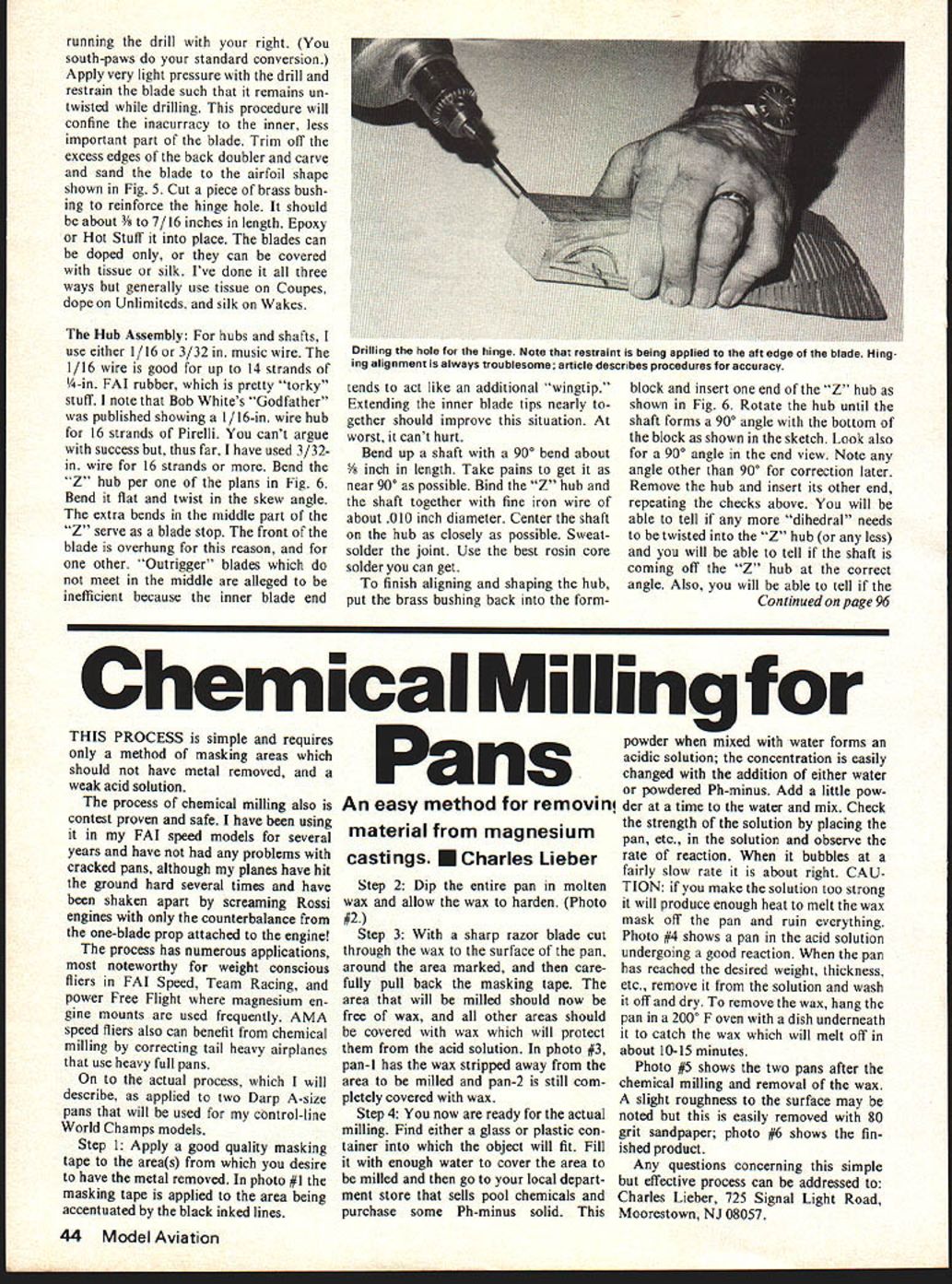
Now to drill the hole. Remove the brass tube from the formblock and strap on the blade with rubber only on the outer one-half or so of the blade. Observe the angle of untwist mentioned above. Carefully restrain the blade with your left hand while running the drill with your right. (You south-paws do your standard conversion.) Apply very light pressure with the drill and restrain the blade such that it remains untwisted while drilling. This procedure will confine the inaccuracy to the inner, less important part of the blade. Trim off the excess edges of the back doubler and carve and sand the blade to the airfoil shape shown in Fig. 5. Cut a piece of brass bushing to reinforce the hinge hole. It should be about 3/8 to 7/16 inches in length. Epoxy or Hot Stuff it into place. The blades can be doped only, or they can be covered with tissue or silk. I've done it all three ways but generally use tissue on Coupes, dope on Unlimiteds, and silk on Wakes.
The Hub Assembly:
For hubs and shafts, I use either 1/16 or 3/32 in. music wire. The 1/16 wire is good for up to 14 strands of 1/4-in. FAI rubber, which is pretty "torky" stuff. I note that Bob White's "Godfather" was published showing a 1/16-in. wire hub for 16 strands of Pirelli. You can't argue with success but, thus far, I have used 3/32-in. wire for 16 strands or more. Bend the "Z" hub per one of the plans in Fig. 6. Bend it flat and twist in the skew angle. The extra bends in the middle part of the "Z" serve as a blade stop. The front of the blade is overhung for this reason, and for one other. "Outrigger" blades which do not meet in the middle are alleged to be inefficient because the inner blade end tends to act like an additional "wingtip." Extending the inner blade tips nearly together should improve this situation. At worst, it can't hurt.
Bend up a shaft with a 90° bend about 3/8 inch in length. Take pains to get it as near 90° as possible. Bind the "Z" hub and the shaft together with fine iron wire of about .010 inch diameter. Center the shaft on the hub as closely as possible. Sweat-solder the joint. Use the best rosin core solder you can get.
To finish aligning and shaping the hub, put the brass bushing back into the formblock and insert one end of the "Z" hub as shown in Fig. 6. Rotate the hub until the shaft forms a 90° angle with the bottom of the block as shown in the sketch. Look also for a 90° angle in the end view. Note any angle other than 90° for correction later. Remove the hub and insert its other end, repeating the checks above. You will be able to tell if any more "dihedral" needs to be twisted into the "Z" hub (or any less) and you will be able to tell if the shaft is coming off the "Z" hub at the correct angle. Also, you will be able to tell if the
Laminated Props/O'Reilly
shaft is centered along the hub. After one round of checks, re-bend and reposition as required. The solder joint will almost certainly break out, don't worry, it will re-solder easily. After resoldering, check again to see that the joint didn't slip while soldering.
Install the blades on the hub and retain them with 1/2A wheel retainers. These are available from Carl Goldberg for 3/32 wire and from Goldberg and Sig for 1/16 wire. Pull both blades to the forward or thrust position. The blade stops will probably prevent them from going all the way forward. Trim the blade stops until both blades are at 90° from the prop shaft. Note that placement of the hinge point behind the blade centerline makes these props flare to higher pitch during the power burst. It is possible to increase or decrease the flare by trimming the blade stops.
You may now complete the front end assembly using the design of your choice. I generally use an ordinary tensioner stop such as you find on the majority of the contest rubber jobs flying. A note of caution may be in order here. If you are flying a short-nosed model which has blades which, when folded, overlap the wing leading edge, a tensioner stop will sometimes disengage for yet one more turn. One tip will hang up on the wing leading edge and the other will hang down and spoil the glide trim. A Montreal stop is the usual fix for this problem, but it will not adapt to a wire hub. A Bob White/Hank Cole stop as described in Bob Meuser's column in the May '76 Model Aviation may be the answer. I am trying a version of the standard tensioner stop with a small .032 wire hook instead of the usual stop screw. So far it has given reliable performance. I would be delighted to receive questions or comments from readers of this article. My address is 4760 N. Battin, Wichita, KS 67220.
Transcribed from original scans by AI. Minor OCR errors may remain.

