
How to Make Wheels & Tires
Harry C. Shoaf
In last month's installment I discussed tire-making techniques for up to 2-1/4-in. diameter wheels. Concluding this month, I go into making both wheels and tires for true "big wheels" — up to 7-1/2-in. diameter for quarter-scalers. (Part 2.)
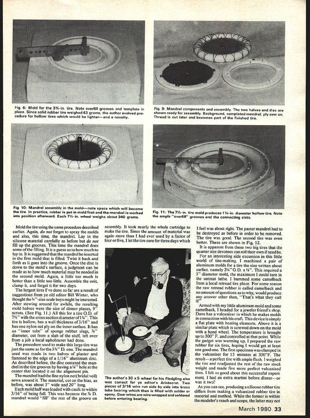
A current project is a 1-1/2-scale Curtiss Fledgling. The full-scale tire was 30" O.D. x 5" D. This makes the model tire 3-3/4" O.D. x 5/8" D., and as such it may be classified as a big tire. The mold (see Fig. 6) was sized to 3-7/8" O.D., undersized for a tight rim fit. Since this tire had over four times the amount of rubber of the biggest yet made, I allowed two days for curing. The results were good although I felt the 43-gram weight was high. But then, I have a light-weight complex anyway. This gave rise to the idea of making this tire hollow. It was felt that the additional work involved would be worthwhile because of the weight savings, and the novelty.
Hollow tire mandrel and disc idea
I decided to try an idea I used on a 2 x 9/32" tire a couple of years ago as an experiment which worked very well. In principle, a thin metal disc is used that has a mandrel around its edge. The mandrel, circular in cross section, is half above and half under the disc edge and is centered in the tire groove so as to form the tire's hollow center. The disc is fixed in position by the mold's alignment pin. The original experiment used a .005" brass shim-stock disc. The mandrel was made of a low-melting-temperature alloy (about 250°F). I formed it in a circular groove with a soldering iron. While these materials worked for the small tire, I felt they wouldn't for the 3-7/8" tire.
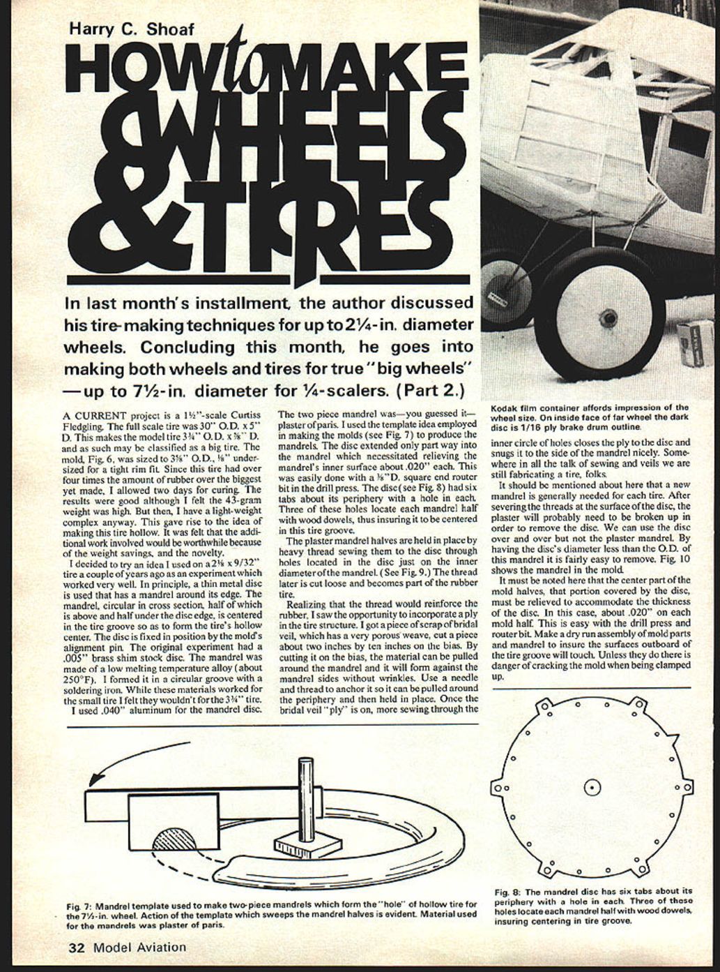
I used .040" aluminum for the mandrel disc. The two-piece mandrel was — you guessed it — plaster of paris. I used the template idea employed in making the molds (see Fig. 7) to produce the mandrels. The disc extended only part way into the mandrel which necessitated relieving the mandrel's inner surface about .020" each. This was easily done with a 1/4" diameter square end router bit in the drill press. The disc (see Fig. 8) had six tabs about its periphery with a hole in each. Three of these holes locate each mandrel half with wood dowels, thus insuring it is centered in the tire groove.
The plaster mandrel halves are held in place by heavy thread, sewing them to the disc through holes located in the disc just on the inner diameter of the mandrel (see Fig. 9). The thread later is cut loose and becomes part of the rubber tire.
Adding a ply reinforcement
Realizing that the thread would reinforce the rubber, I saw the opportunity to incorporate a ply in the tire structure. I got a piece of scrap bridal veil, which has a very porous weave, and cut a piece about two inches by ten inches on the bias. By cutting it on the bias, the material can be pulled around the mandrel and will form against the mandrel sides without wrinkles. Use a needle and thread to anchor it so it can be pulled around the periphery and then held in place. Once the bridal veil "ply" is on, more sewing through the inner circle of holes closes the ply to the disc and snugs it to the side of the mandrel nicely. Somewhere in all the talk of sewing and veils we are still fabricating a tire, folks.
It should be mentioned here that a new mandrel is generally needed for each tire. After severing the threads at the surface of the disc, the plaster will probably need to be broken up in order to remove the disc. We can use the disc over and over but not the plaster mandrel. By having the disc's diameter less than the O.D. of the mandrel it is fairly easy to remove. Fig. 10 shows the mandrel in the mold.
Mold preparation and molding procedure
It must be noted that the center part of the mold halves — that portion covered by the disc — must be relieved to accommodate the thickness of the disc. In this case, about .020" on each mold half. This is easy with the drill press and router bit. Make a dry-run assembly of mold parts and mandrel to insure the surfaces outboard of the tire groove will touch. Do this unless you want the danger of cracking the mold when it is clamped up.
Mold the tire using the same procedure described earlier. Again, do not forget to spray the molds and also, this time, the mandrel. Lay in the silicone material carefully as before but do not fill up the grooves. This time the mandrel does some of the filling. It is a guess as to how much to lay in. It is suggested that the mandrel be inserted in the first mold that is filled. Twist it back and forth as it goes into the groove. Once the disc is down to the mold's surface, a judgment can be made as to how much material may be needed in the second mold. Again, a little too much is better than a little too little. Assemble the unit, clamp it, and forget it for two days.
Very large tires
The largest tires I've done so far are a result of suggestions from ye old editor Bill Winter, who thought the 3/4-size scale boys might be interested. After stewing around for a while, the resulting mold halves were the size of dinner plates, 9" across (see Fig. 11). All this for a tire O.D. of 7-1/2" with a cross-section diameter of 1-1/4". This tire is hollow, has a wall thickness of 3/16" and has one nylon net ply on the inner surface. It has an "inner tube" of sponge rubber slugs, 7/8" diameter, cut from a slab of the stuff left over from a job a local upholsterer had done.
The procedure used to make this large tire was just the same as for the 3-3/4" tire. The mandrel used was made in two halves of plaster and fastened to the edge of a 1/16" aluminum disc. As described before, the disc centered the mandrel in the tire grooves by having a 1/8" hole at the center that located on the alignment pin. The mandrel had the fine nylon net (bridal veil) sewn around it. The material, cut on the bias as before, was about 3" wide and 20" long.
Each mold half was loaded with caulk to within 3/16" of being full. This was because the 7-1/2" mandrel would "fill" the rest of the groove on assembly. It took nearly the whole cartridge to make the tire. Since the amount of material was again more than I had ever used by a factor of four or five, I let it cure for three days, which I feel was about right. The plaster mandrel had to be destroyed as before in order to be removed. The tire was good. The second tire was even better. These are shown in Fig. 12.
It is apparent from these two big tires that the quarter-scale devotees can roll their own if need be.
Vulcanized rubber (camelback) experiment
For an interesting side excursion in this little world of tire-making, I machined a pair of aluminum molds for a tire the size written about earlier, namely 2-3/4" O.D. x 1/2". This required a 3" diameter mold, the maximum I could turn in the Unimat lathe. I bummed some camelback from a local retread tire place. For some reason the raw retread rubber is called camelback and no amount of questions as to why would produce any answer other than, "That's what they call it."
Armed with my little aluminum mold and some camelback, I headed for a jeweler friend's shop. Dave has a vulcanizer in which he makes molds in connection with his craft. This device is simply a flat plate with heating elements. Above it is a similar plate which is screwed down on the mold with a hand wheel. The temperature is brought up to 300°F and controlled at that point. While the gadget was warming up, I prepared the raw rubber for six tires, hoping I would get at least one good one. The first specimen was clamped in the vulcanizer for 15 minutes at 300°F. The result — a perfect tire with ample flash. I weighed the tire and readjusted the rest of the raw stock weight and made five more perfect vulcanized tires. I felt so good about this successful experiment I had an extra martini before dinner—or was it two?
As you can see, producing a silicone rubber tire differs from making a vulcanized rubber tire in material and method. While the former is within the modeler's reach and scope, the latter may not — machine lathes and vulcanizers are not that readily available to most of us.
Making wheels
Making wheels for your tires isn't very complicated if you stay with the disc wheel, or a covered simulated-spoke wheel. If you are interested in a true spoke wheel, I suggest you get them from Fulton Hungerford, who has the best. Although I'm familiar with his manufacturing process, having observed and enjoyed a few bull sessions with him, describing his methods would be too complicated and lengthy for this article.
I'm not going to describe all the possible ways to make various wheels. That would have to include simple things like a double paper cone for baby R.O.G.'s on up. The intent here is to show what I've used with my tires.
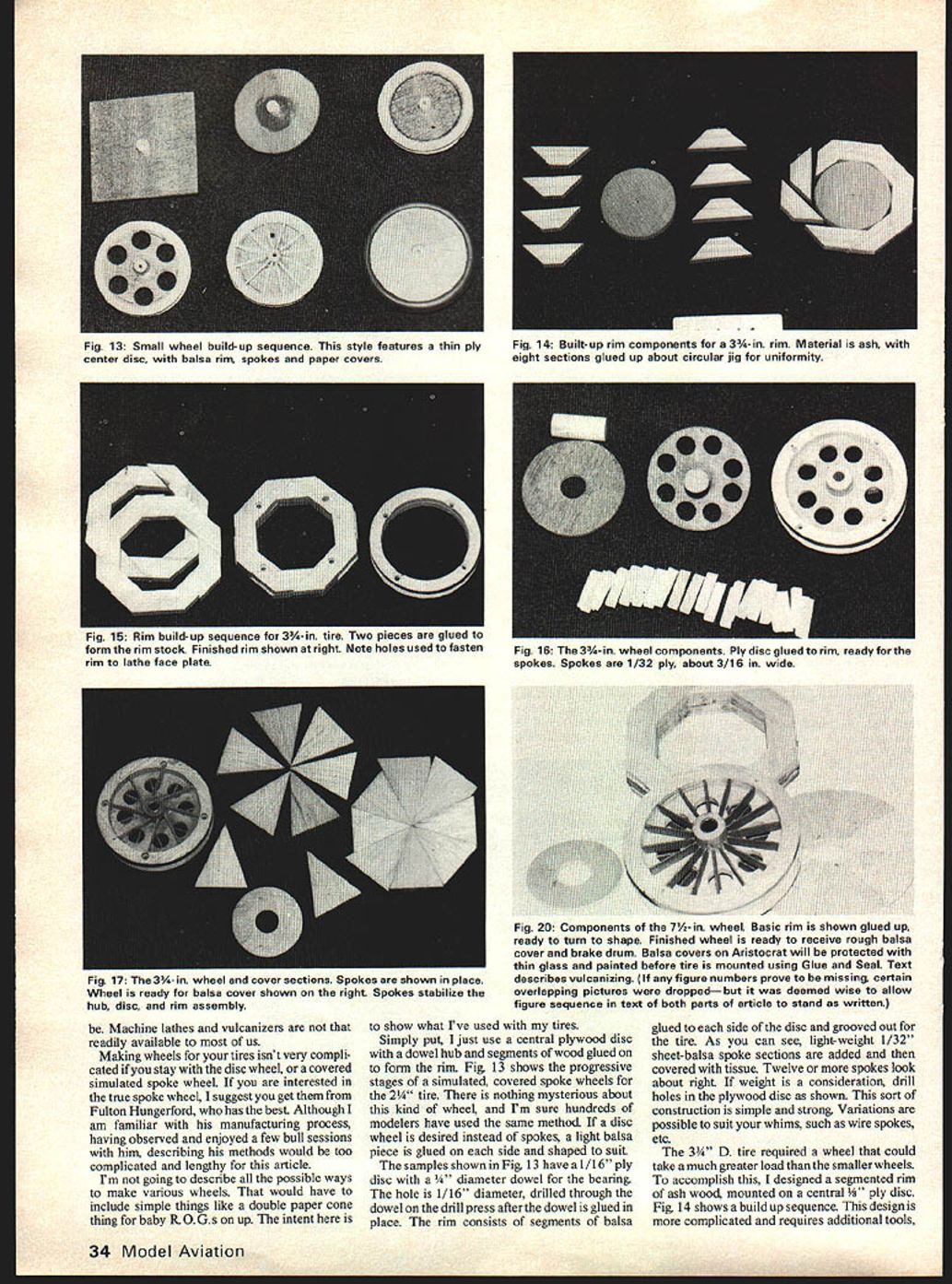
Simply put, I use a central plywood disc with a dowel hub and segments of wood glued on to form the rim. Fig. 13 shows the progressive stages of a simulated, covered-spoke wheel for the 2-1/4" tire. There is nothing mysterious about this kind of wheel, and I'm sure hundreds of modelers have used the same method. If a disc wheel is desired instead of spokes, a light balsa piece is glued on each side and shaped to suit.
The samples shown in Fig. 13 have a 1/16" ply disc with a 3/16" diameter dowel for the bearing. The hole is 1/16" diameter, drilled through the dowel on the drill press after the dowel is glued in place. The rim consists of segments of balsa glued to each side of the disc and grooved out for the tire. As you can see, light-weight 1/32" sheet-balsa spoke sections are added and then covered with tissue. Twelve or more spokes look about right. If weight is a consideration, drill holes in the plywood disc as shown. This sort of construction is simple and strong. Variations are possible to suit your whims, such as wire spokes, etc.
Heavier-duty 3-1/4" wheel
The 3-1/4" D. tire required a wheel that could take a much greater load than the smaller wheels. To accomplish this, I designed a segmented rim of ash wood, mounted on a central 1/4" ply disc. Fig. 14 shows a build-up sequence. This design is more complicated and requires additional tools such as a lathe. The hub is again a hardwood dowel and is 1/2" D. It is drilled to take a brass tube liner.
As Fig. 15 shows, two segmented rim units are glued together with the joints reversed for strength. A rim constructed of three or four thinner units would be even tougher if the need existed. The rims were then turned and finished.
The discs were rough cut, strung on a 1/4" dowel and glued in place. They should be as square with the dowel as you can make them. When dry, cut the dowels and size the discs to fit the rim. I do this by placing the hub in a hole drilled in a piece of 3/8" plywood and rotating the disc blank on a band saw. Clamp the plywood in place so that the blade will cut at a greater disc radius than you want and then make a few cuts, inching them down to the final size. Glue the disc in place, being careful to center it in the plane of rotation as best you can (see Fig. 16).
The spokes are 1/32" ply about 3/16" wide. I cut the spoke lengths slightly longer than the hub-to-rim distance. This eliminates the need for an exact fit by placing the spoke against the hub side (see Fig. 17). The spokes, when dry, are sanded flush with the rim so that the balsa cover stock will fit flat when added later. The spokes are a structural necessity that stabilizes the hub-disc-rim assembly.
With the structure now complete the wheel was returned to the lathe face plate and the hub drilled to receive a 3/16" I.D. brass tube bearing. The bearing is installed after the hub is trimmed to length by flaring the tube ends as shown in Fig. 18.
The balsa wheel covers are made up of eight pie-shaped segments glued to the hub spokes and rim. I shaped the covers by chucking the wheel in the drill press via a 3/16" bolt.
As in the case of the smaller wheel, if a covered-tire wheel effect is wanted, it's pretty easy to stick in a bunch of stainless wire spokes. In this instance, it would be prudent to dope on a silk cover instead of paper.
Assuming the wheel is now complete with paint and ready to roll, mount the tire. Do this by bonding the tire to the rim using the silicone glue and seal material. Let it set for 24 hours before rough usage.
Quarter-scale (big) wheel
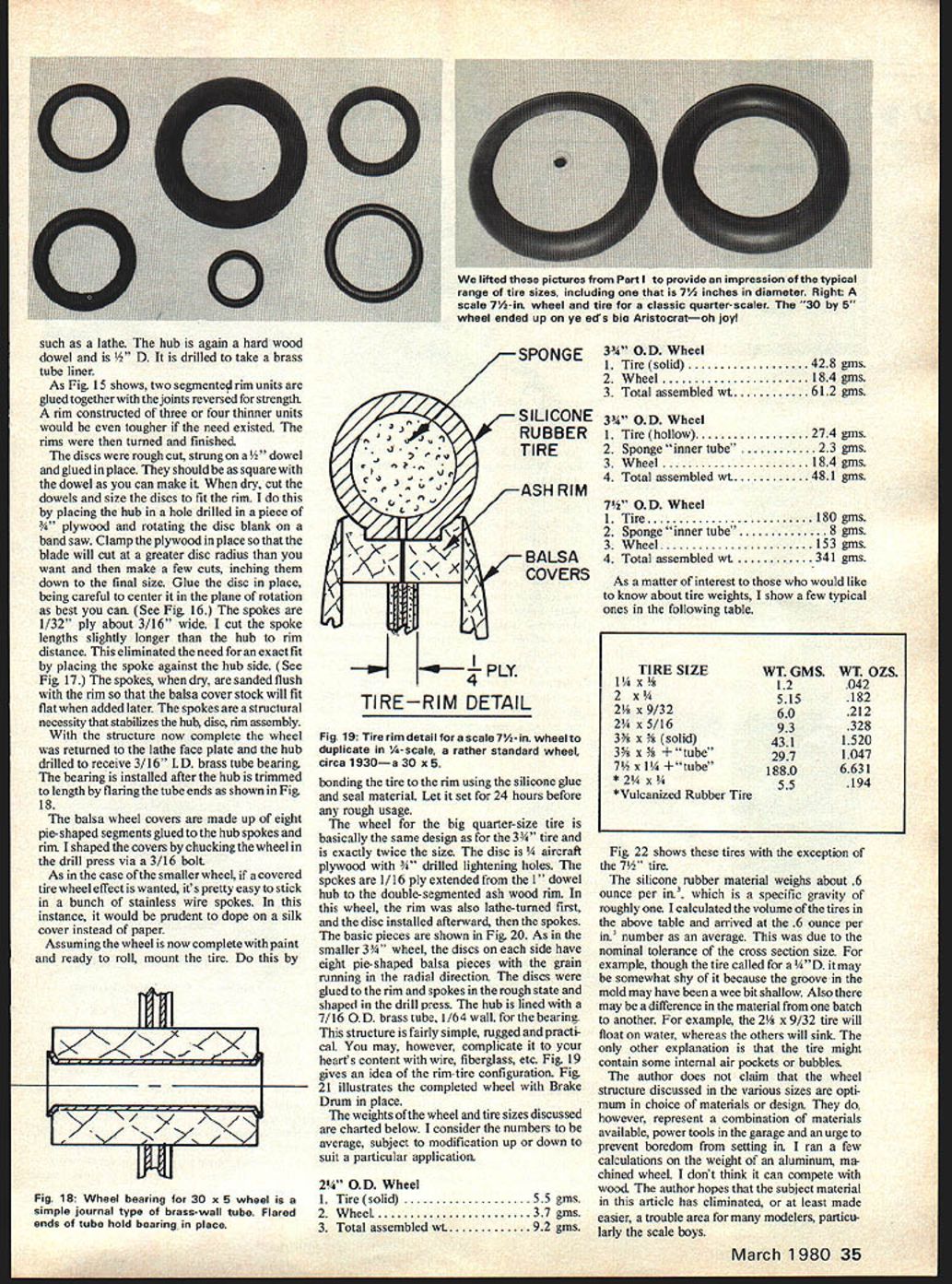
The wheel for the big quarter-scale tire is basically the same design as for the 3-3/4" tire and is exactly twice the size. The disc is 1/4" aircraft plywood with 3/16" drilled lightening holes. The spokes are 1/16" ply extended from the 1" dowel hub to the double-segmented ash wood rim. In this wheel, the rim was also lathe-turned first, and the disc installed afterward, then the spokes. The basic pieces are shown in Fig. 20. As in the smaller 3-3/4" wheel, the discs on each side have eight pie-shaped balsa pieces with the grain running in the radial direction. The discs were glued to the rim and spokes in the rough state and shaped in the drill press. The hub is lined with a 7/16" O.D. brass tube, 1/64" wall, for the bearing. This structure is fairly simple, rugged and practical. You may, however, complicate it to your heart's content with wire, fiberglass, etc. Fig. 19 gives an idea of the rim-tire configuration. Fig. 21 illustrates the completed wheel with brake drum in place.
Weights
The weights of the wheel and tire sizes discussed are charted below. I consider the numbers to be average, subject to modification up or down to suit a particular application.
2-1/4" O.D. Wheel
- Tire (solid) ..................................... 5.5 gms.
- Wheel ............................................. 3.7 gms.
- Total assembled wt. .............................. 9.2 gms.
Fig. 22 shows these tires with the exception of the 7-1/2" tire.
The silicone rubber material weighs about 6 ounces per in.3, which is a specific gravity of roughly one. I calculated the volume of the tires in the above table and arrived at the 0.6 ounce per in. number as an average. This was due to the nominal tolerance of the cross-section size. For example, though the tire called for a 3/4" D., it may be somewhat shy of it because the groove in the mold may have been a wee bit shallow. Also there may be a difference in the material from one batch to another. For example, the 2-1/4" x 9/32" tire will float on water, whereas the others will sink. The only other explanation is that the tire might contain some internal air pockets or bubbles.
The author does not claim that the wheel structures discussed in the various sizes are optimum in choice of materials or design. They do, however, represent a combination of materials available, power tools in the garage, and an urge to prevent boredom from setting in. I ran a few calculations on the weight of an aluminum machined wheel. I don't think it can compete with wood. The author hopes that the subject material in this article has been of interest, or at least has made an area that troubles many modelers — particularly the scale boys — a little easier.
Transcribed from original scans by AI. Minor OCR errors may remain.

