
How to: Overhaul Two-Cycle Engines
Walt Wilson
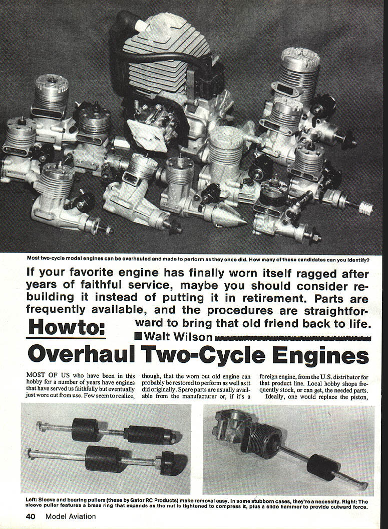
If your favorite engine has finally worn itself ragged after years of faithful service, consider rebuilding it instead of retiring it. Parts are frequently available, and the procedures are straightforward to bring that old friend back to life.
Introduction
Most of us who have been in this hobby for years have engines that served faithfully but eventually wore out. The worn-out engine can often be restored to perform as well as it did originally. Spare parts are usually available from the manufacturer or the U.S. distributor for foreign engines. Local hobby shops frequently stock, or can obtain, the needed parts.
Ideally, one would replace the piston, piston rings, wrist pin, connecting rod, cylinder liner, and possibly crankshaft bearings. A complete overhaul sometimes costs as much as a new engine; often it can be done substantially less. Compare costs before embarking on the overhaul.
Disassembly
- Remove the carburetor, cylinder head, front plate, backplate, etc.
- Before disassembling, note and write down identifying features that indicate sides, orientation of plates, top/bottom, which way the cylinder head or piston/connecting rod face, and which is the front of the engine. If no such features exist, mark parts for future reference.
- Gaskets should be replaced. If a gasket must be reused, carefully remove it before submerging parts in cleaning solution and note its face orientation.
- Note that screws may be different lengths—record which screw goes where.
Some engines have integral front plates; in some cases the piston/connecting rod can't be removed without removing the cylinder liner. On engines with sufficient clearance you can slip the connecting rod off the crank pin. If you only need to remove dirt after a crash, you may be able to wash or wipe enough away to avoid complete disassembly. However, for a thorough overhaul you must remove the piston and connecting rod.
Removing the Cylinder Sleeve
- Most ABC (aluminum piston, brass sleeve, hard chrome-plated) liners don't fit the crankcase very tightly and can be removed by taking off the front plate and crankshaft and pushing the piston toward the top of the bore. Keep gently pushing and the sleeve will usually come out.
- If the piston doesn't start the sleeve, insert a wooden stick (popsicle stick) through the exhaust port and push upward against the piston. Do not use metal objects in the exhaust port — use wood — and avoid excessive force to prevent damage.
If carbon and varnish deposits exist around the exhaust port the sleeve may not come out. Use a heavy-duty cleaner such as automotive carburetor cleaner, following directions and working in a well-ventilated area. Beware: some plastic parts will be destroyed by solvent; cleaners can pit or discolor metal if left too long.
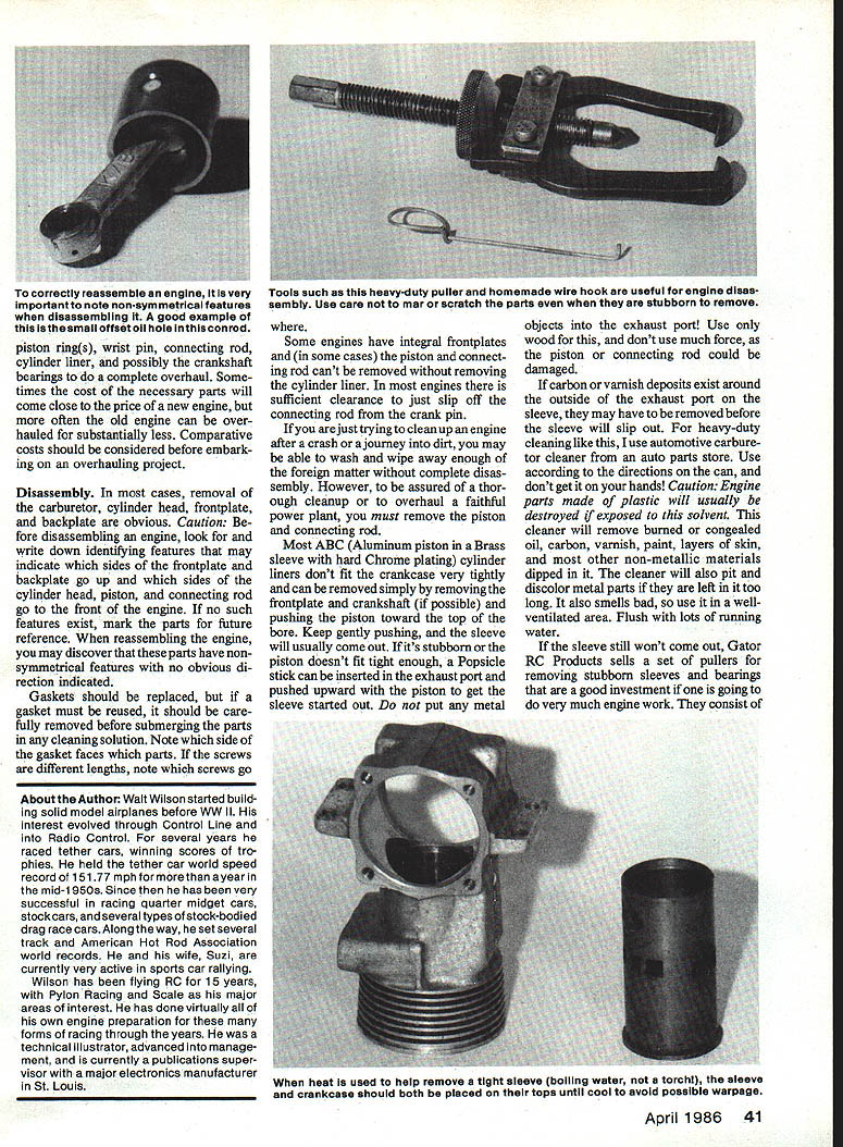
If the sleeve still won't come out, Gator RC Products sells pullers for removing stubborn sleeves and bearings. The puller uses a split brass ring between a tapered and a flat washer that expands when a nut is tightened on a threaded rod; the weighted side-hammer on the rod is used to knock out the sleeve. At last report, these pullers were available only for larger engines (.60 and .40–.52-size bearings) but may fit some smaller sleeves.
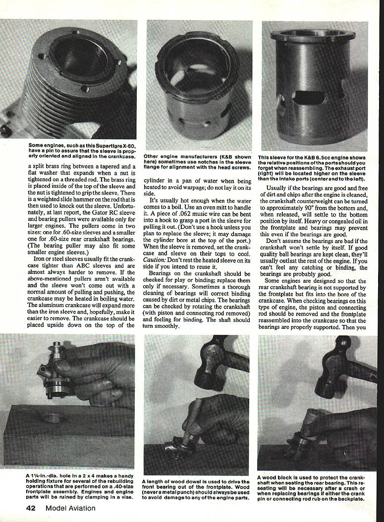
Iron or steel sleeves usually fit the crankcase tighter than ABC sleeves and are harder to remove. If pullers aren't available and normal pulling doesn't work, heat the crankcase in boiling water to expand aluminum more than the iron sleeve. Place the crankcase upside down on top of the cylinder in a pan of water when heating to avoid warpage; do not lay it on its side. Use an oven mitt. A piece of .062 music wire bent into a hook can help grasp a part in the sleeve for pulling it out. (Don't use a hook unless you plan to replace the sleeve; it may damage the cylinder bore at the top of the port.) After removal, set the crankcase and sleeve on their tops to cool. Do not rest a heated sleeve on its side if you intend to reuse it.
Bearings and Crankshaft
- Check bearings for play or binding; replace only if necessary. A thorough cleaning will sometimes correct binding caused by dirt or metal chips.
- To check bearings: remove piston and connecting rod, rotate the crankshaft (with piston/rod removed), and feel for smooth rotation. If the shaft turns smoothly, bearings are probably good.
- A quick check: if bearings are good and clean, the crankshaft counterweight turned to about 90° from bottom will settle to the bottom position by itself when released. Heavy or congealed oil may prevent this even with good bearings—don't assume bearings are bad because the crankshaft doesn't settle.
Some engines have the rear crankshaft bearing unsupported by the frontplate; it fits into the crankcase bore. For these, remove piston and rod and reassemble the frontplate into the crankcase so bearings are properly supported while checking.
Cleaning Bearings
- First try cleaning the frontplate and bearings by soaking in hot water with liquid dishwashing detergent. After a few minutes, remove and flush with running lukewarm water while rotating the crankshaft to flush the bearings. Repeat if necessary.
- When bearings free up, dry the assembly with paper towels and blow out as much water as possible. Then oil the crankshaft and bearings liberally with a light machine oil such as Marvel Oil. If you don't remove water and oil steel parts well, they will rust.
- Alcohol may be used for washing, but detergent is inexpensive and effective.
If cleaning can't free the bearings, proceed to remove the prop drive hub and crankshaft.
Removing Prop Drive Hub and Crankshaft
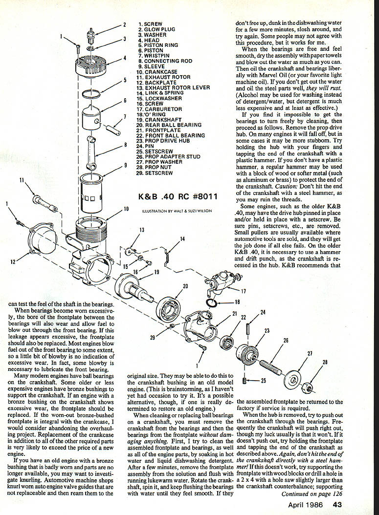
- Remove the prop drive hub. It may fall off; if stubborn, hold the hub and tap the end of the crankshaft with a plastic hammer. If you must use a regular hammer, protect the crankshaft end with a wood block or softer metal (aluminum/brass). Do not hit the crankshaft directly with a steel hammer; you may ruin the threads.
- Some engines (e.g., older K&B .40) may have the hub pinned or secured with a setscrew—remove pins/setscrews. Small pullers (automotive) can help if other methods fail. On older K&B .40s you may need a hammer and drift punch; K&B recommends returning the assembled frontplate to the factory if service is required.
- After hub removal, try to push out the crankshaft through the bearings. If it won't push out, hold the frontplate and tap the crankshaft end as above. If still stubborn, support the frontplate with wood blocks or drill a hole in the frontplate (hole saw) slightly larger than the crankshaft counterbalance to create clearance for the crankshaft; then tap again. If all else fails, most automotive machine shops have a press that will remove the crankshaft.
Inspect the crankshaft for scoring, grooves, or discoloration on the crankpin or around/between the bearings. If there is roughness or wear, replace the crankshaft. If outer races of bearings have been turning in the frontplate, replace the frontplate as well.
Removing and Installing Bearings in the Frontplate
- The front bearing inner race is almost always smaller than the bore in the frontplate. Use a wood dowel the size of the bore and a hammer to tap out the front bearing.
- If the rear bearing stayed on the crankshaft, the puller that removed the drive hub may get it off.
- If you have a Gator RC bearing puller, removal is straightforward. Otherwise, try heating the frontplate in boiling water; aluminum will expand more than the steel bearing outer race, allowing removal. Use a wire hook through the bearing inner bore if space permits. Use a cooking mitt to handle the hot frontplate.
When installing new bearings, gently tap them into place in the frontplate with a plastic hammer. Tap around the outer race so the bearing goes in evenly. Use the crankshaft as a guide to keep the bearing straight. Tap the bearing all the way into the bore and keep everything clean—new bearings are easily ruined.
Oil the bearings and insert the crankshaft. On engines like the K&B .40 the prop drive hub must be aligned so pin holes and setscrew match the hole and flat on the crankshaft; it may be tight and require gentle hammering with protection. Drive in the roll pin and tighten the setscrew if required. Rotate the crankshaft to ensure it turns freely.
Pistons, Rings, and Connecting Rods
- Ring-type pistons, sleeves, and piston pins are available separately and need not be purchased in matched sets. Fit of piston in ring-type engines is not critical for most applications except special racing engines.
- Some engines have a small pin in the ring groove to hold the ring in a given position relative to the ports—check for such a pin before installing the ring.
- Some rings (e.g., Dykes ring in a K&B .40) have a top and bottom; direction is usually obvious. When in doubt, look at the original piston and ring.
To check and set ring end gap:
- Insert the ring into the cylinder sleeve and push it a little way in with the piston to square it in the bore.
- Gap should be about 0.002 in. per inch of bore between ring ends.
- If no feeler gauge is available, check for visible light between the ends for bores 1 in. or less.
- If no gap is visible, remove the ring and file or sand the ends carefully—file a little and check often. Remove all burrs after filing.
- Slip the ring over the piston into the ring groove and align the ends with any locating pin.
Check the fit of the big end of the connecting rod on the crankpin; it should not bind. If it binds, obtain another connecting rod—fixing an existing one is unlikely to help. Compare new and old connecting rods and determine front orientation. Frequently, an oil hole on one side of the big end must face a specific direction. Pistons with a baffle or "fence" on top should have the baffle toward the intake ports.
Oil parts and assemble the connecting rod to the piston using the wrist pin. Many wrist pins have pads in the ends made of Teflon (or similar) to prevent scuffing of the sleeve—make sure pads are in place. Some wrist pins do not go all the way through the piston and have one exposed end; in that case the pad is on the exposed end. Ensure the piston pin opening does not align with any ports in the sleeve.
Lapped iron pistons/sleeves are available only in matched sets—no fitting required. ABC pistons are designed to fit tightly at the top of the stroke; heat from running expands the sleeve more than the piston, so this tight fit is normal. Some ABC engines also use piston rings.
Sleeve Orientation and Reassembly into Crankcase
- If the frontplate was integral with the crankcase and the sleeve had to be removed before the piston and connecting rod, you must reassemble the piston and rod onto the crankpin before inserting the sleeve. Slip the piston into the sleeve from the bottom as the sleeve is inserted into the crankcase—this takes care and patience but is manageable.
- Some sleeves have tapered bores at the bottom to assist in compressing rings when installing.
If no alignment features exist on the sleeve flange, orient the sleeve as follows:
- In every two-cycle model engine encountered here, the exhaust port(s) are closer to the top of the sleeve than the intake ports.
- Locate the exhaust ports on the sleeve and face them toward the exhaust port in the crankcase, aligning ports as you push the sleeve into place.
When parts are clean, the sleeve usually slips into place with finger pressure. If it hangs up, ensure ports are aligned, place crankcase and sleeve upside down on a clean surface, and push firmly with the palm of your hand on the bottom of the crankcase.
If the sleeve still will not push in with reasonable pressure, place the sleeve in a freezer for an hour or so to contract it slightly, then try again. Recheck port alignment after insertion.
For ABC piston/rod assemblies, the assembly must be in the sleeve at the time the sleeve is assembled into the crankcase. Iron pistons and ring-type pistons are usually assembled after the sleeve is in the crankcase (except with integral frontplates).
Oil the piston, wrist pin, and sleeve generously before assembly. For pistons with rings, align any ring-gap locator pin or orient the ring gap so it is not in line with any ports. Push the ring into the groove with fingernails, and gently push the piston into the sleeve—maintain gentle pressure on the top of the piston while compressing the ring if necessary. When seated, align the piston so the bore in the lower end of the connecting rod is perpendicular to the crankshaft centerline.
Frontplate Installation
- If a gasket is used, place it on the frontplate in the proper position. If reusing a gasket, put it exactly as it was removed (same orientation). No sealers are necessary.
- Oil the crankpin, align it with the connecting rod, and slip the frontplate into place. With the backplate removed, support the connecting rod with your fingers as you insert the frontplate and crankpin. If parts don't go in easily, find the problem—don't force it.
- Turn the crankshaft a few times to ensure smooth movement. Insert all frontplate screws and snug them all. Tighten a little at a time, going from one screw to the one directly opposite and working around until all are tight. Be careful not to strip threads—the crankcase is aluminum and threads are delicate.
- Check that the sleeve is still aligned with crankcase ports, then install the cylinder head. Most modern engines don't use head gaskets, but some use thin shims under the head—replace any shim that was present. Snug screws, then tighten gradually in the same opposite-screw sequence.
Squish Band Clearance (Plastigage)
Some engines use a squish band head with a specific clearance. Plastigage (soft plastic wire) can check this clearance:
- Place a small piece of Plastigage on the top of the piston where it contacts the squish band before installing the head.
- Install the head, rotate the crankshaft a couple of times, then remove the head.
- Compare the mashed Plastigage width to the scale provided with the product.
- If the Plastigage is mashed too wide, clearance is too close—use a thicker shim or combination of shims.
- If Plastigage isn't mashed wide enough, clearance is too great—use a thinner shim or no shim.
- When correct, clean off the Plastigage and reassemble the head.
Don't worry about connecting rod and wrist pin clearances allowing the piston to come closer; in a running two-cycle engine, compression and combustion maintain constant down pressure on the piston.
Backplate, Final Checks, and Break-In
- If a gasket is used on the backplate, position it and mount the backplate. Tighten screws using the opposite-screw sequence described earlier.
- Rotate the crankshaft and ensure the crankpin/connecting rod are not rubbing the backplate. If binding is detected, tighten a propeller on the crankshaft to hold it forward. If that doesn't cure it, remove the frontplate, use a wood block to protect the crankshaft, and tap the back of the crankshaft in the center with a hammer to ensure crankshaft and rear bearing are fully seated in the forwardmost position. Reassemble and recheck.
- When the fully assembled engine turns freely (except new ABC engines, which may bind at the top of the stroke initially), install a fresh glow plug and reassemble the carburetor. If an O-ring seals the carburetor, hold down on the carb against the O-ring while tightening screws or nut.
After overhauling, break in the engine using the same procedures recommended when it was new.
Notes and Limitations
- This information applies generally to two-cycle, front-intake RC engines of conventional construction. Other engine types may require different procedures.
- If you have a better method, the author welcomes correspondence: Walt Wilson, 3000 Persimmon Dr., St. Charles, MO 63301.
Addresses
- Gator RC Products, 3713 Pompano Dr., Pensacola, FL 32504
- K&B Manufacturing, 12152 Woodruff Ave., Downey, CA 90241
- Marvel Oil Company, Inc., Port Chester, NY 10573
- Sealed Power Corp. (Plastigage), 100 Terrace Plaza, Muskegon, MI 49443
Transcribed from original scans by AI. Minor OCR errors may remain.

