
How to Trim a Model — Part II
Continuing last month's discussion, this article shows how to develop two force arrangements (FAs). You should refer to Part I (February issue) and also have "A Primer on Aerodynamics" (September 1992 issue) available. I assume you have decided on the general arrangement and objectives for the design (from experience or a chosen commercial design), selected the style of airfoil (undercambered, flat-bottomed, semisymmetrical, or symmetrical) and the angle of attack you will use.
It's time to translate knowledge of aerodynamics into action. The logical way to proceed is to lay out a force arrangement (FA) — a visible depiction of the aerodynamic forces involved. Use paper large enough for at least a half-scale sketch; too small a scale makes it hard to see what's happening.
Hal deBolt
Laying out the FA (step-by-step)
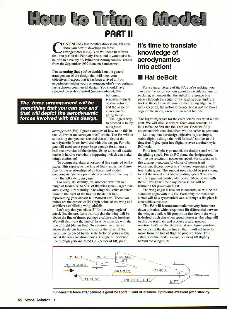
- Draw a horizontal line centered on the paper. This is the line of flight — the datum line for relationships of forces and model components.
- Strike a point about one-quarter of the way in from the left side of the paper. This will represent the wing center of lift (C/L).
- Tail moment arms for adequate stability fall in the range of 40%–50% of the wingspan (larger than 40% gives ultra stability). From the wing C/L, strike a point to the right representing your chosen tail moment arm — this is the stabilizer C/L.
- If the wing incidence (angle of attack) is, for example, 3°, draw a 3° angle-of-incidence line through the wing C/L. If the wing is above the thrust line (e.g., cabin fuselage), measure the thrust-line offset above the datum and plot that as well.
- For clarity, trace the airfoil contour about the incidence line. Remember: the airfoil reference line passes through the center of the leading edge and runs back to the extreme aft point of the trailing edge. With rare exception, the reference line is not the lower edge, even for flat-bottom sections.
First Force Arrangement — Simple, stable flight
Objective: a simple, self-stabilizing design (old-time free flight, sport free flight, trainer-style RC).
Key choices and rationale:
- Design speed: gliding speed for free flight; maximum power-on speed for RC.
- Power: use just enough power to pull the model slightly above gliding speed for a gradual climb; excess power is undesirable for free flight.
- Stabilizer: preferably symmetrical (a flat plate may suffice).
- Stabilizer incidence: set slightly positive (example: +1° on the datum) so it does not need to move from the line of flight to produce work. This positions the model's mean center of lift slightly behind the wing's C/L.
- Nose moment arm: distance from wing C/L to propeller; chosen to help achieve the desired CG location. Keep the nose moment arm as short as practical to reduce destabilizing gyroscopic forces from the spinning propeller.
Trimming and CG:
- Trim is done with CG location. Initial CG: about 10% of the wing chord ahead of the mean C/L; alternatively, locate the CG at the wing's C/L as a safe starting point.
- If flight shows a stalling tendency in the glide or an abnormal angle of climb in RC, move the CG forward until the line of flight appears parallel with the horizon.
- If the line of flight appears to be downward, move the CG rearward.
- For average-size models, CG movements for trimming should not exceed about 1/2 inch at any one time. Adjust by moving internal components or adding small amounts of ballast (e.g., lead shot in modeling clay) near nose or tail.
- Once tuned, replace temporary ballast with permanent weight.
Outcome: With this FA and a properly tuned CG, flight will be smooth and stable with automatic recovery from nose-down attitudes. This arrangement favors safety over aerobatic capability.
Center of resistance and thrust line
- The center of resistance (center of total drag) should be known to relate forces, especially the thrust point.
- Total drag includes profile drag (from the front profile or cross section), inherent drag (drag from producing lift/stabilizing forces), and skin-friction drag (air clinging to surfaces).
- A practical method to estimate the center of profile drag: reproduce the exact front view of the craft on graph paper, measure the area and determine the centroid of that equivalent flat plate. The centroid of the profile drag is usually close to the center of total drag for most normal configurations.
- For maximum efficiency, the thrust line should coincide with the center of resistance. Designers sometimes offset thrust line to produce a nose-down (thrust above center of resistance) or nose-up (thrust below center of resistance) reaction to achieve special handling characteristics.
Second Force Arrangement — Duration with RC-assisted limited engine run
Objective: maximize duration for an RC-assisted powered model with a limited engine run (or a powered free-flight type). Two flight-performance goals:
- Stay aloft as long as possible (minimize sink rate / maximize L/D).
- Gain maximum altitude during the limited power run (best rate of climb).
These goals tend to oppose each other: high lift increases drag, which hurts climb rate. The FA must use complementary factors and compromises.
FA setup for duration
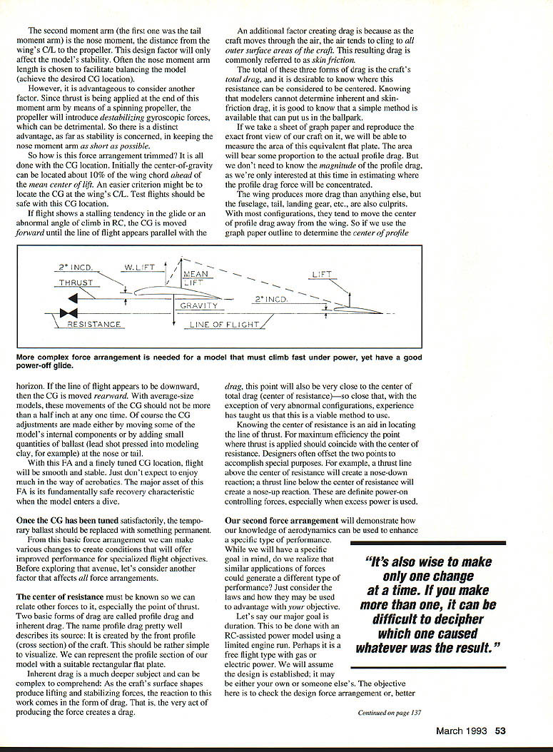
- Choose a high-lift wing airfoil with the least drag for the best L/D ratio.
- Set the wing at its best L/D angle — for example, +2° incidence.
- Use a high-lift flat-bottom section for the stabilizer, also set at about +2° on the FA. (This FA assumes RC control is available for recovery; automatic recovery is not a primary goal here.)
- With both wing and stabilizer producing lift, the model's mean C/L will be between the two; experience indicates it will be aft of the 50% station on the wing chord. For this FA assume mean C/L ≈ 55% of chord.
- For stability, locate the CG ≈ 10% of chord ahead of the mean C/L → starting CG ≈ 45% of the wing chord.
- Determine the center of resistance as before. Place the thrust line parallel to the line of flight and as high above the center of resistance as practical to help control high power (a high thrust line produces nose-down moment).
Trimming procedure — power-on and glide
General principles:
- "It's also wise to make only one change at a time. If you make more than one, it can be difficult to decipher which one caused whatever was the result."
- Two flight envelopes must be trimmed: (A) fast power-on climb (steep but not looping), and (B) flat glide with low sink rate.
- Establish power-on performance first; glide trim will relate to power trim.
Power-on trimming:
- Begin with low-power tests.
- If the model climbs too steeply and/or stalls: increase stabilizer incidence (equivalent to giving down elevator) until the climb is steady without stalling. This adjusts the lift proportion between wing and stabilizer.
- Add more power and repeat as necessary until full power produces the steepest climb angle with positive flying speed.
- If the low-power tests show no stalling tendency, you may be able to reduce stabilizer incidence slightly to increase climb angle — though this is uncommon for average designs.
Glide trimming:
- With power-on trim fixed, use small CG movements to fine-tune the glide without upsetting power-on trim. Small movements (≤ 1/2 inch) can affect glide more than power-on behavior.
- A simple rule of thumb: trim elevator until the line of flight is parallel to the horizon in glide. Note the elevator trim setting on landing:
- If there is up trim present, move the CG rearward until neutral elevator yields a horizontal glide.
- If there is down trim present on landing, move the CG forward until neutral elevator yields a horizontal glide.
- Repeat as needed, remembering not to move the CG more than about 1/2 inch at a time.
Evaluation:
- Judge sink rate and glide angle visually by comparing the line of flight to the horizon — the ideal is parallel to the horizon.
- The combined power and glide adjustments should produce a compromise that yields excellent performance for the chosen objectives.
- If an adjustment has an intolerable effect on another parameter, back off and re-compromise. Only the wing incidence is fixed once chosen.
Applying our knowledge — final notes
- With plenty of lift available, rate of climb is determined by available power, weight, and drag. In FA planning, drag is the main controllable factor.
- Use lift sources that produce the least drag penalty to improve climb and sink performance.
- Remember that each aerodynamic choice affects the others: no single factor dominates. Use the FAs and trimming strategies in conjunction to reach the desired compromise for safe, high-performance flight.
- Replace temporary ballast with permanent weight once trim is finalized.
- Above all, have fun!
Transcribed from original scans by AI. Minor OCR errors may remain.

