
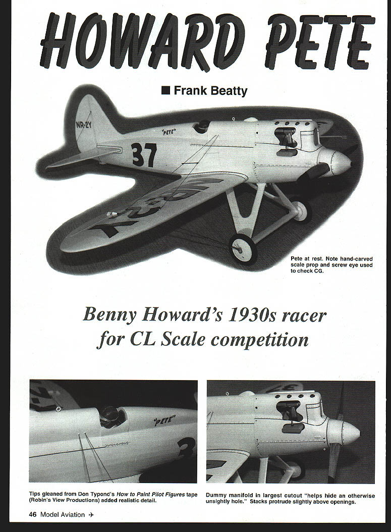
HOWARD PETE
Frank Beatty
Benny Howard's 1930s racer for CL Scale competition
Full-scale aircraft engineers face challenging design and performance requirements that often require compromise or tradeoff. The same holds true for model designers. It will make a big difference in how the model is designed and built, for instance, if it is to be a weekend sport model or an all-out competition machine.
The Pete was intended as a competition machine to participate in a future Nationals. To enhance true-scale appearance, the control system leadout wires are enclosed in the wing. The sharply curved fillet at the wing-to-fuselage joint complicates locating the bellcrank. Space limitations and clearances dictated the use of a short-span (2-1/2 inch) bellcrank, even though that might induce somewhat sensitive fore-and-aft pitch-axis flight qualities.
As design work progressed it was noted that the bellcrank mounting plate must also serve as the rear undercarriage strut-mounting plate. That raised concerns that a hard landing might buckle the plate and render the control system inoperable (that fear proved groundless). It also seemed prudent to build the wing center section as a separate unit to facilitate bellcrank and rear undercarriage strut installation.
Alternate approach for a weekend sport model:
- Locate a 3 to 3-1/2 inch long-span bellcrank on top of the engine mounts between bulkheads 6 and 9.
- Build the fuselage and wing center section as one unit, eliminating concerns about undercarriage strut location.
- Revised cutouts will be required for rerouting throttle and elevator pushrods.
Tradeoffs, anyone?
SPECIFICATIONS
- Type: CL Scale
- Wingspan: 40-3/4 inches
- Engine: O.S. .32
- Flying weight: approx. 65 ounces
- Construction: Built-up
- Covering/finish: Sig Koverall and Sig dope
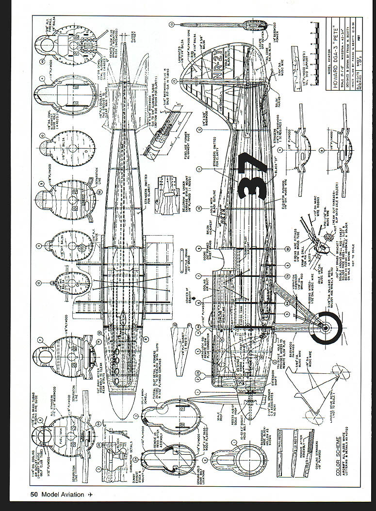
CONSTRUCTION
Though the Pete is not especially difficult to build, construction sequence is important. Build the tail surfaces, wing center section, and wing outer panels first so construction will not be delayed when those parts are needed.
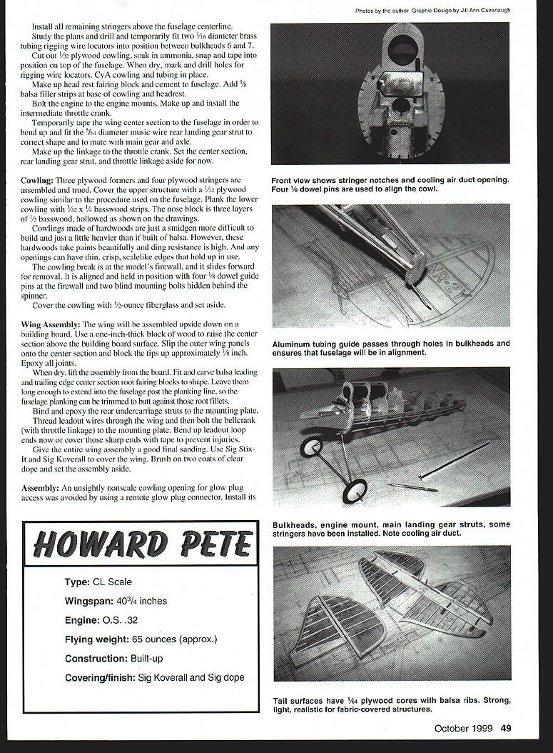
Stabilizer and Elevators
Thin, scale-like, strong fabric-covered tail surfaces can be achieved by building around an internal 1/16" plywood core.
Steps:
- Cut 1/16" plywood cores for the stabilizer and elevators.
- Cement spars and balsa ribs to these cores.
- Soak four 1/16" x 1/4" balsa strips in ammonia and bind them around each outline; when dry, cement them to the structures.
- Install the elevator horn and Robart hinges. Build up epoxy around these hardware items at the plywood cutouts — these joints are quite strong and need no other reinforcement.
- Drill the stabilizer spar and use cyanoacrylate (CyA) glue to attach 1/16" brass tubing into these holes for rigging wire locators.
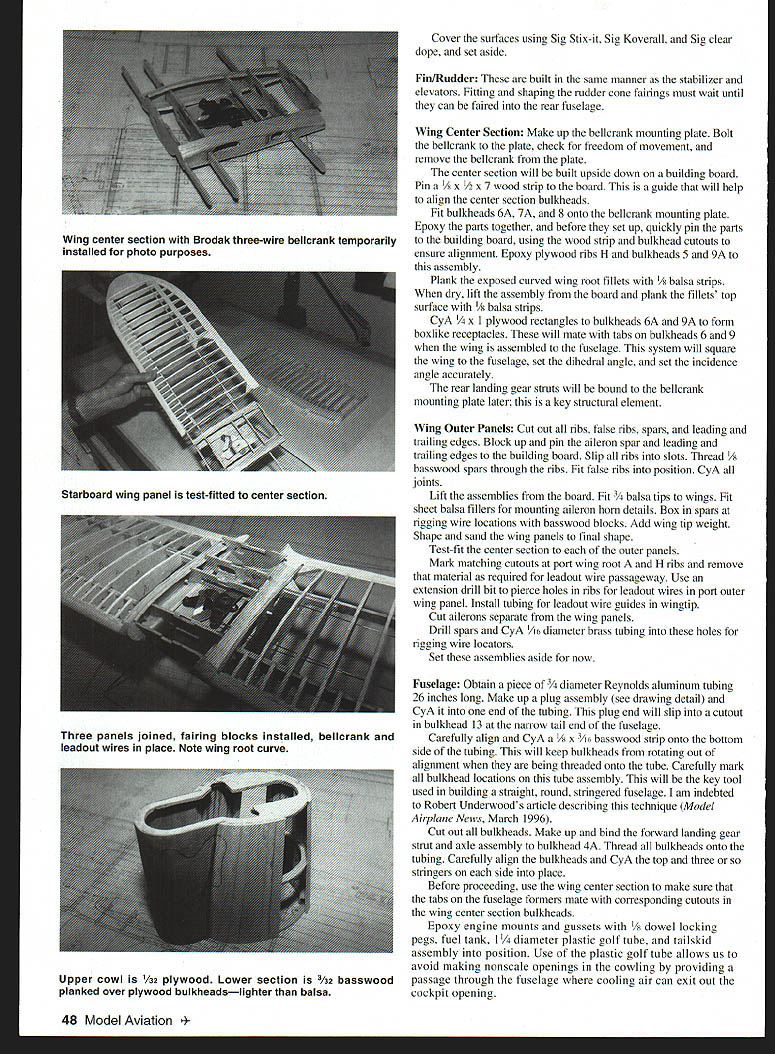
Wing Center Section
Make up the bellcrank mounting plate. Bolt the bellcrank to the plate, check for freedom of movement, then remove the bellcrank for assembly.
Build the center section upside down on the building board:
- Pin a 5/8" x 1/2" x 7" wood strip to the board as a guide to align center section bulkheads.
- Fit bulkheads 6A, 7A, and 8 onto the bellcrank mounting plate. Epoxy parts together; before the epoxy sets, quickly pin parts to the building board using the wood strip and bulkhead cutouts to ensure alignment.
- Epoxy plywood ribs and bulkheads 5 and 9A to the assembly.
- Plank the exposed curved wing root fillets with 1/8" balsa strips while dry on the board. When dry, lift assembly and plank the fillets' top surface with 1/8" balsa strips.
- CyA plywood rectangles to bulkheads 6A and 9A to form box-like receptacles that will mate with tabs on bulkheads 6 and 9. When the wing is assembled to the fuselage the system will square the wing, and set dihedral and incidence angles accurately.
- The rear landing gear struts will be bolted/bound to the bellcrank mounting plate later; this is a key structural element.
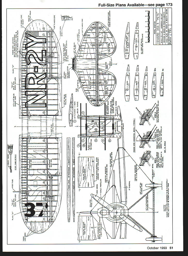
Wing Outer Panels
- Cut out all ribs, false ribs, spars, leading and trailing edges.
- Block up and pin the aileron spar, leading and trailing edges to the building board.
- Slip ribs into their slots and thread 3/32" basswood spars through the ribs.
- Fit false ribs in position and secure with CyA joints.
- Lift assemblies off the board.
- Fit 3/4" balsa tips to the wings and sheet balsa fillers for the aileron horn mounting details.
- Construct box spars and install rigging wire locators (1/16" brass tubing where indicated).
- Add wing tip weight and shape/sand the panels to final shape.
- Test-fit the center section to each outer panel. Mark and cut matching cutouts at the port wing root A and H ribs as required for leadout wire passage.
- Use an extension drill bit to pierce holes in ribs for leadout wires in the port outer wing panel. Install tubing for leadout wire guides in the wingtip.
- Cut ailerons separate from the wing panels, drill spars, and CyA 1/16" brass tubing for rigging wire locators.
- Cover surfaces using Sig Stix-It, Sig Koverall, and Sig clear dope, then set aside.
Fin and Rudder
- Built the same manner as stabilizer and elevators.
- Fit and shape rudder cone fairings later when they can be faired into the rear fuselage.
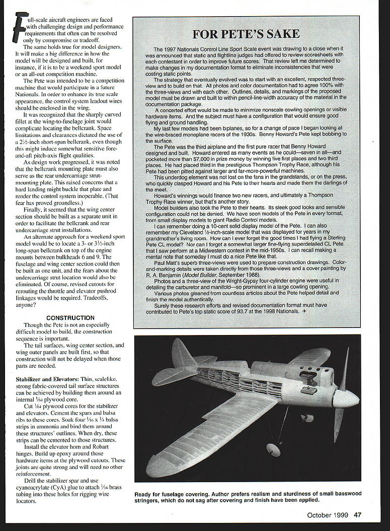
Fuselage
Key technique: use a straight aluminum tube as the spine to build a round, stringered fuselage.
Steps:
- Obtain 3/4" diameter Reynolds aluminum tubing, 26" long. Make up a plug assembly (see plans) and CyA it into one end — this plug slips into a cutout in bulkhead 13 at the tail end.
- Carefully align and CyA a 1/8" x 1/16" basswood strip onto the bottom side of the tube to keep bulkheads from rotating when threaded onto the tube.
- Mark all bulkhead locations on the tube. Cut out all bulkheads.
- Make up and bind the forward landing gear strut and axle assembly to bulkhead 4A.
- Thread all bulkheads onto the tubing, carefully align them and CyA the top and about three stringers on each side into place.
- Use the wing center section to ensure tabs on the fuselage formers mate with corresponding cutouts in the wing center section bulkheads.
- Epoxy engine mounts and gussets with 1/8" dowel locking pegs, install fuel tank, 1/4" diameter plastic golf tube (as a passage for fuel or air exit), and tailskid assembly.
- Install remaining stringers above the fuselage centerline.
- Drill and temporarily fit two 1/16" diameter brass tubing rigging wire locators between bulkheads 6 and 7.
- Cut out 1/32" plywood cowling, soak in ammonia, snap and tape into position on top of the fuselage. When dry, mark and drill holes for rigging wire locators and CyA cowling and tubing in place.
- Make up headrest fairing block and cement to the fuselage. Add 1/8" balsa filler strips at base of cowling and headrest.
- Bolt engine to mounts and make/install intermediate throttle crank.
- Temporarily tape the wing center section to the fuselage to bend and fit the 5/64" diameter music wire rear landing gear strut to the correct shape and to mate with main gear and axle.
- Make up the linkage to the throttle crank. Set center section, rear landing gear strut and throttle linkage aside for now.
Cowling
- Assemble three plywood formers and four plywood stringers; true the assembly.
- Cover the upper structure with 1/32" plywood similar to fuselage procedure.
- Plank the lower cowling with 3/32" x 1/4" basswood strips.
- The nose block is three layers of 1/2" basswood, hollowed as shown on the drawings.
- Hardwood cowling is slightly heavier but more durable and accepts paint well; openings can have thin, crisp edges.
- The cowling breaks at the firewall and slides forward for removal. Align and hold with four 1/4" dowel guide pins at the firewall and two blind mounting bolts hidden behind the spinner.
- Cover the cowling with 1/2-ounce fiberglass and set aside.
Wing Assembly
- Assemble the wing upside down on the building board. Use a 1" thick block to raise the center section from the board.
- Slip outer panels onto the center section and block the tips up approximately 1/8". Epoxy all joints.
- When dry, lift the assembly from the board.
- Fit and carve balsa leading and trailing edge center-section root fairing blocks to shape, leaving them long enough to extend into the fuselage past the planking line so the fuselage planking can butt against the root fillets.
- Bind and epoxy the rear undercarriage struts to the mounting plate.
- Thread leadout wires through the wing and bolt the bellcrank (with throttle linkage) to the mounting plate.
- Bend up leadout loop ends or cover sharp ends with tape to prevent injuries.
- Final-sand the entire wing assembly, cover with Sig Stix-It and Sig Koverall, and brush on two coats of clear dope.
Assembly
- Install a remote glow plug connector to avoid an unsightly nonscale cowling opening. Access the connector through a scale hole in the bottom of the cowling.
- Attach the wing to the fuselage. Tabs at bulkhead separation lines should mate with the receptacles on the wing center-section bulkheads; these should align the wing in all axes, but double-check before epoxying.
- Cement and dowel-pin the fin to the stabilizer, then mount the assembly to the fuselage.
- Install all elevator pushrods and throttle linkages and check for freedom of movement.
- Fit 1/8" x 1/4" sheet balsa fairings all the way around each wing root at the fuselage, then add the remainder of the stringers.
- Fit, shape, and cement fairing blocks at the fin-to-stabilizer joint.
- Sand the entire fuselage and cover using Sig Stix-It, Sig Koverall and two coats of Sig clear dope.
- Install fairings on undercarriage axle and struts (basswood preferred for resistance to compression/fatigue). Cover all struts with 1/2-ounce fiberglass.
Finish
A word on weight and finishing:
- My model, assembled with engine, wheels and hardware, weighed approx. 51 ounces before final finish and hung nose-down about 5° when suspended from its designated CG location. I expected a completed weight in the mid-60s.
- A fatal error: I replaced an old compressor and switched dope brands. The new compressor applied heavier paint/sealer coats than intended, resulting in a much heavier, tail-heavy model. Time constraints led me to finish rather than strip paint.
Recommended finishing process:
- Apply several coats of sanding sealer with wet-or-dry sanding between coats.
- Apply coats of white dope, sanding after every coat or so until satisfied.
- Mask racing and registration numbers and spray black where required.
- Apply gold accents using the glass-transfer lettering technique:
- Prepare a pane of glass with very soapy water; when dry, spray the glass gold.
- Cut out the "Pete" and "NR-27" lettering from the gold film, lift from the glass and apply to the model using thinner as bonding agent.
- Protect with a clear dope overspray.
- Rub talcum lightly over gold lettering to provide a base for pen work. Use a black top-filter pen or line pen to draw pinstriping around lettering; protect with clear dope overspray.
- Apply panel lines using the talcum-and-panel-line-pen technique.
- Simulate rivets or screw heads with a Pilot Silver Marker and protect with clear dope.
- Spray several coats of Sig clear dope over the entire model, then hand-rub with compound and polish.
Final Assembly
- Install rigging wires on the wings and tail. Details for brackets at axles and sweated tubing fittings at each rigging wire junction are on the plans.
- Note: the original top-of-wing axle fittings failed on the first flight; these were replaced by sweat-tubing hardware, which has held up well. The rigging is considered functional and the model should not be flown without it.
- Cockpit doors: form from .010" sheet brass, attach with miniature pins; draw hinge line with a panel-line pin and protect with clear dope.
- Add remaining details: vibration dampeners, exhaust stacks, dummy carburetor and manifold.
- Install a dummy pilot if visible in flight; paint per recommended techniques (I used methods from Don Typond's videotape "How to Paint Pilot Figures").
- Carved propeller: make from four 7/32" basswood laminations; carve, stain, paint, varnish and bolt to the model.
FLYING
There is no question that excess weight is bad and should be avoided. Lately, however, I've come to appreciate some advantages of a heavier model: they are less tossed about by wind and can taxi more predictably. That said, overweight models are less forgiving of pilot error and require ample power and correct balance.
Advice and observations:
- If built as intended with a ready-to-fly weight of 60–65 ounces, the Pete is an excellent machine in flying and ground handling.
- My overweight Pete (approx. 90 oz) flew satisfactorily when properly balanced and powered, but demanded discipline from the pilot.
- Balance: nose should hang down about 5° when suspended from the CG location.
- Use shorter-than-normal lines for control feel—about 52 feet.
- The O.S. .32 provides ample power; the Pete flies fast and smooth.
- Avoid high flight in significant wind — the lightly loaded wing can stall suddenly with bad consequences.
- Power-on landings: maintain sufficient power and speed to keep flying until touchdown; gradually reduce power and altitude until rolling on main gear, then reduce power further and use a bit of elevator to set the tail on the ground.
- The trick is to maintain enough speed to avoid stalling on final, yet be slow enough to avoid excessive ballooning or bouncing on landing.
During learning flights I made several hard landings and one cartwheel when wheels dug into a soft dirt surface. Surprisingly, no compression, fatigue or stress cracks appeared on the model.
So: build light or fly right.
Frank Beatty 2608 Pontoon Rd. Granite City, IL 62040
Transcribed from original scans by AI. Minor OCR errors may remain.

