
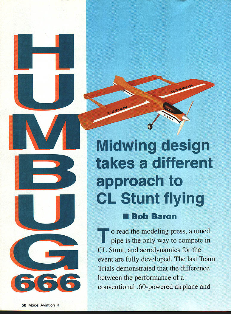
Humbug 666
Midwing design takes a different approach to CL Stunt flying
Bob Baron
To read the modeling press, a tuned pipe is the only way to compete in CL Stunt, and aerodynamics for the event are fully developed. The last Team Trials demonstrated that the difference between the performance of a conventional .60-powered airplane and the tuned-pipe .40 is less than the scatter between the judges. With several very fine large engines coming on the scene (SuperTigre .51, Discovery Retro .55 from the Ukraine, and Double Star .60 from Moldova), I felt it was time to once again explore aerodynamic avenues for improved performance.
Using conventional engines allows more time to be devoted to the airplane, since these engines are relatively trouble-free and are easy to adjust through air intake and compression changes (compared to piped engines).
In discussions with Bill Netzeband, it seemed that the combination of the Humbug concept (characterized by a midwing configuration coupled with a very large high-aspect-ratio stabilizer/elevator) with a more optimum use of flaps could lead to an interesting result.
Since the effect of flaps on the Humbug could not be predetermined with any confidence, it was decided to make the flap-to-elevator ratio adjustable over a large range. Since the associated drag with the flaps was also unpredictable, it was decided to build the airplane so that numerous engines could be installed with a minimum of cutting on the airframe.
A dural landing gear was used to allow easy replacement if more prop clearance was required, and the two-position mounting pattern ensured safe takeoffs from grass and asphalt surfaces. The tank compartment was made large enough to allow whatever capacities were anticipated for the various candidate engines, with enough vertical room for shimming to ensure that the run characteristics were not compromised.
The old trick of incorporating a finite amount of play in the flap-to-elevator connection was explored, making the feature adjustable along the flap-to-elevator ratio.
Humbug 666 — specifications
- Type: CL Stunt
- Wingspan: 53 3/4 inches
- Engine: SuperTigre .51 / Discovery Retro .55 (tested)
- Flying weight: 58 ounces (typical)
- Construction: Built-up with sheet-covered wing
- Covering / finish: Dope
Humbug 666 — weight data (summary)
- Total moments: 212.93
- Total weight: 58.25 ounces
Structural weights (ounces)
- Booms: 1.00
- Wing: 16.00 (includes 2 oz. extra in flaps)
- Stabilizer/elevator: 2.50
- Fuselage: 8.50
- Structural weight: 28.00 (≈48% of total)
Finish
- Covering/paint: 5.25
- Paint on fuselage/fillets: 3.50
- Finish weight: 8.75
- Projected minimum weight: 56.25 ounces
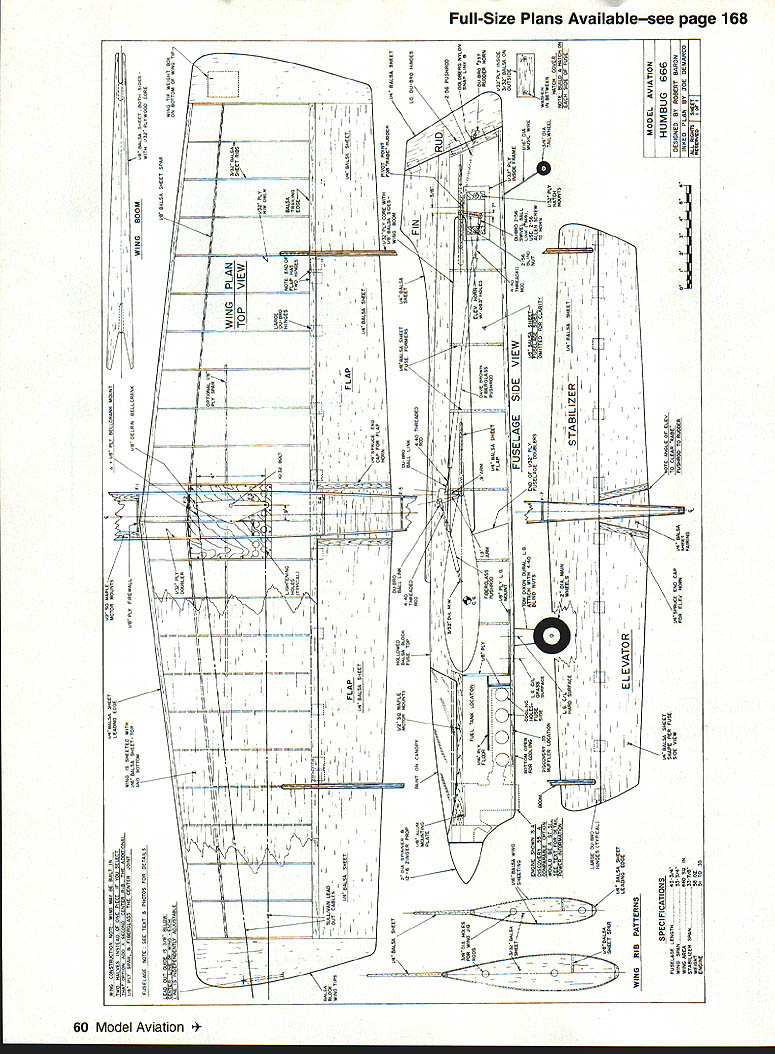
No additional narrative appears on the plans page — it contains full-size plans, drawings, and labels for the Humbug 666.
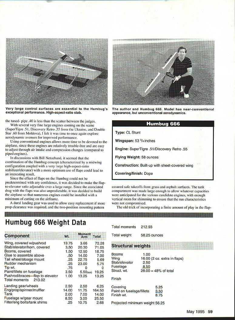
Humbug's wing area (660 square inches) is midrange for contemporary Stunt airplanes. The weight (58 ounces) is also very typical for present-day airplanes. Consequently, any performance increases or perceived improvements in handling and ease of adjustment can be attributed to the aerodynamics rather than an unusually low wing loading.
The flaps were first placed between the booms because it was structurally the natural thing to do. Using only the portion between the booms for flaps minimized the prospect of the tip stalling before the center of the wing, and the booms could conceivably add to the efficiency of the flaps by acting as tip plates.
The original engine was a Fox .40 with the flap-to-elevator ratio set at 0.66. After a few short flights, it was evident that more power would be needed to make this airplane perform competitively. Even with the 60%-span flaps moving much less than the elevator, it was clear that the drag was too much for the engine, and the wing could be induced to stall in hard corners. An O.S. FSR .45 that had been slightly detuned by Tom Dixon was then installed. This was a significant increase in power over the Fox .40, and the model immediately showed promise of performing on a par with full-span flapped models.
After trying an assortment of props, an 11.5 x 5.5 made from a Zinger 12 x 6 appeared to provide a good balance of vertical thrust and comfortable lap speeds in the 5.0–5.2 second range. At this time, serious testing of various flap-to-elevator ratios began, as the .45 was easily pulling the model around on 70-foot lines. I first increased the flap travel to provide a one-to-one flap/elevator ratio. Not only were the corners sharper, but the plane was easier to fly through the maneuvers (although level flight still required more-than-average attention).
Tom Dixon and I have joked that "if a little is good, too much is just about right." We have since revised this to "too much is still insufficient." Following this premise, I increased flap travel to 1.35 flap / 1.00 elevator. Again the corners were sharper and the airplane became still easier to fly. With this ratio, the plane could be hammered hard in any maneuver with no sign of dropping or inducing any stall.
The only time the increased drag showed up as a potential problem was when flying an outside loop entered at only 30° elevation using full control; this maneuver resulted in the bottom of the loop still having approximately 10 feet of clearance from the ground. Try this maneuver with a piped airplane and see how safe it feels.
Full control in flight was measured by wrapping wire on one of the leadouts and measuring the travel used after the wrap was pushed by the leadout guide. This full control was measured at approximately 29° of flap to 22° of elevator. When using full control on a complete outside loop, the model would slow visibly and just start to wobble, indicating an approaching tip stall.
At this point the Humbug's handling characteristics were very pleasant, but it begged the question of what would result when more power was installed. I went to a SuperTigre .51. When coupled with a plastic spinner and lightweight expansion muffler, it weighed no more than the FSR .45 with the original metal spinner and Adamisin muffler. With no CG or weight change, a significant increase in torque was now on tap.
The result, using the same prop, was no change in level-flight speed, but the full-control outside loop resulted in a clean, tight loop with no wobble on exit. We now had an airplane that could not be caused to stall or wobble regardless of the control input, yet still had extremely competitive performance.
With the increased torque (and hence braking action) of the .51, Humbug was even easier to fly, since the acceleration in a vertical dive was reduced from that of the .45.
Time for the duration of the wingover, from the beginning of the pullup to the end of the pullout, was a mere 3.02 seconds. The theoretical time for this (at a 5.0-second lap, assuming a corner radius of 15 feet) would be 2.69 seconds if there was no loss in airspeed, so only 0.33 second was lost due to the plane slowing through the corner and climbing vertically. This demonstrates the significant vertical capability provided by the .51, and also the apparent efficiency of the model in not creating excessive drag in developing the lift through the corner.
With the increased torque of the .51, I decided to once again try a 1:1 flap-to-elevator ratio, since there was a chance that this would produce a tighter corner than the 1.35:1 ratio. Sure enough, the corner was tighter, but it came at a price of noticeably more slowing than the previous ratio. Even with the increased torque of the .51, the sharp increase in drag was too much for the engine, and a wobble (most likely due to tip stall) could be induced by high control inputs.
We now appeared to have stumbled onto a new way to trim maximum performance into a CL Stunter: to optimize the flap-to-elevator ratio. In the past, flying just below stall was achieved by reducing the total control travel or by moving the CG forward. Both techniques lead to reduced performance compared to that provided by optimizing the flap-to-elevator ratio.
Much of the test flying was done in very light (0–2 mph) wind. This has the advantage of allowing any imbalance in the trim to be easily spotted, since wind is not a factor. The many flights under these conditions clearly demonstrated the importance of having the engine power come on and off in the classic Stunt fashion.
By adjusting the compression, the increase in power during the two-cycle portion can be altered. With too little compression, the airplane slows too much and begins to lose tension. With too much compression, the airplane lurches with the surge in power and becomes unbalanced, leading to a wobble. Flying under these marginal conditions emphasized how delicate the balance is between two- and four-cycle power, and why having the two–four break is important to smooth execution of the pattern.
The control system was installed with minimal play, using a Delrin bellcrank and Du-Bro ball-end sockets at the flap and elevator horns. Note the angle of the horns at the flap and elevator. The angle of the bellcrank pushrod at the flap horn (created by the bellcrank location behind the main spar) and the angle of the elevator pushrod at the flap and elevator horns, due to the midwing configuration, lead to unequal travel unless the controls are installed per the plans.
The CG at 20% of mean aerodynamic chord, combined with the large stabilizer, indicated that the Humbug would be stable — and it was. However, level flight still required concentration to maintain smoothness. I began to experiment with varying amounts of controlled play introduced into the elevator horn. I removed the ball from the socket and sleeved the retaining screw for the socket with different sized tubing, then safety-wired the arrangement with a washer on the screw. Varying amounts of free play can be incorporated into the control system without changing any other variable.
I found that when there was sufficient play to allow the trailing edge of the elevator to move 1/8 in. total with the flaps restrained, the airplane could immediately be flown more easily in level flight.
On the wingover, it was apparent that the model was maintaining a more accurate track. I was testing on a particularly good day with smooth air and a cloudless blue sky. Under these conditions I could see the smoke trail from the muffler, which confirmed that the track in the wingover was extremely straight.
I was anticipating a dead spot in the intersection of the horizontal and vertical eights, due to the play in the controls, but I could not detect it. Putting play in the elevator-to-flap linkage appears to be one of those rare instances when there is a clear benefit with no apparent downside.
CONSTRUCTION
Fabrication of Humbug 666 is conventional for CL Stunt models, but a few building techniques are worthy of note.
The original model was built using conventional open-bay wing construction and was covered with 21st Century cloth. Although somewhat easier to apply than MonoKote, the 21st Century material contributed little to the stiffness of the wing in torsion and was noticeably weaker than MonoKote in this regard. In addition, the weight penalty compared to MonoKote was approximately two ounces.
Since it has been established that stiffer airframes perform much better in windy weather, the construction was changed to a sheet-covered wing with dope finish. The only weight penalty for the second-generation airplane is the weight of the additional planking.
The solid-sheet flaps shown on the drawing save about two ounces over the more complex built-up sheet flaps that followed the airfoil on the original. The hinging on the prototype had to be done at the ends of each flap, and the stiffness required precluded lightening the original flaps by cutting out sections. Available data seem to indicate that there is no aerodynamic benefit to having the flaps be a continuation of the airfoil, compared to the simpler flat flap used on the majority of Stunt models. The faired-in flap looked good on the plans, but lost its appeal once the actual building took place.
I recommend that the wing and tail be built and finished (exclusive of color) separately from the fuselage. Knowing the weights of the wing and tail as well as the fixed hardware, it is possible to determine the nose length by summing the moments of the individual components such that the center of gravity is located per the plans, with no ballast required.
The nose length shown on the plans reflects the best estimates, based on the original model, and should be very close. The optimum nose length will depend on component weights, engine selection, finish, etc.
The plan shows a Discovery Retro .55 engine, soon to be imported from the Ukraine and distributed by Tom Dixon. This engine has a front intake and rear exhaust and is sold with a very lightweight muffler. The power — based on direct-comparison tests run with a .12 & 6 Zinger — is more than a SuperTigre .51 and the weight is the same. The SuperTigre .51, however, has been demonstrated to work very well with this design and is readily available. The muffler, being mid-fuselage instead of outside, eliminates the eccentric weight and drag of the side-exhaust engine.
I would not suggest increasing the engine size to a .60 because of the weight penalty of the engine, fuel tank, structure, and fuel.
When building the fuselage, make a crutch consisting of the two engine bearers glued to the cross-grained 1/2-inch spacer. This glue joint should be made on a very flat surface such as a piece of glass or a hard table. Mount the two aluminum rails or the engine bearers with small screws that have been countersunk below the surface of the aluminum. These rails prevent local crushing of the engine bearer when the engine is tightened down.
Make the aluminum rails flat and parallel by sanding the crutch assembly on sandpaper that is laying on a hard, flat surface. When this crutch assembly is incorporated into the fuselage, it is assured that the engine casing will not be distorted, even if there are slight misalignments in the rest of the fuselage.
Assembly of the fuselage sides together with the crutch and plywood bulkhead just forward of the wing is best done with the fuselage upside down on a flat surface using a slow-curing epoxy. The entire fuselage is built with the top block and bottom sheet tack-glued in place and all the shaping and sanding completed prior to installation of the wing. The top block is then removed and hollowed to 1/8" wall thickness. All cowl details should also be completed at this time.
Installation of the booms, stabilizer, and pushrod assembly to the wing is done prior to the fuselage installation. The nature of the booms pretty much assures accurate alignment of the stabilizer incidence, provided the booms are cut accurately. However, it is always a good idea to check the stabilizer with a Robart incidence meter; misalignment here will result in poor handling characteristics.
The fuselage is now glued to the wing/tail assembly, taking care to make the cutout in the fuselage for the stabilizer a good fit. Again, use slow-curing epoxy to provide time to accurately align the fuselage.
Once it is confirmed that the controls operate smoothly, the gear mount, bottom block and top block can be installed. Note that the pushrod from the flap to the elevator is made from composite for stiffness, as the adjustable feature of the control system does not allow pushrod braces to be used in the fuselage.
I install the top block with slow-curing epoxy, using masking tape to position the block until the glue dries. The slow-curing epoxy provides a superior bond and allows ample time to accurately position components and for this reason I use it for critical operations where alignment takes precedence over speed of assembly.
Trimming and flying is similar to any other Stunter. Determine that the engine is running reliably and provides lap times of 5.0–5.2 seconds on 70 feet of line. The best prop pitch is between 5-1/4" and 5-1/2", using a Prather pitch gauge. It is very important to sand the blades to this pitch, as most props are off in pitch by at least 1/2". Rev-up blades tend to be 1/2–1" low; Zinger props are fairly close, but not constant at all blade stations.
No commercial prop provides the exact pitch required for the best performance of a given design; a flier should become comfortable with altering the pitch of commercial props to suit a particular airplane.
The initial center of gravity should be very close to that shown on the plans. If one wing is high in level flight, but low in inverted flight, most likely the wing is warped. The rigid construction of the all-sheet wing requires the time-honored tradition of tweaking the flaps to level the wings. Be sure, however, that the elevators are parallel to one another, since the large empennage on this design is sufficiently powerful to roll the airplane.
Set the original control at the elevator horn such that the flaps move 1.35 to the elevator moving 1.00. With the wings level and the engine running well, begin flying various hard-corner maneuvers, such as an inside square.
If the level flight speed is close to 5.0 seconds per lap and the engine lacks power in the maneuvers, reduce head clearance in 0.005 inch increments. If the engine tends to come on too hard in the maneuvers and runs too slowly in level flight, it may be overcompressed, requiring additional head shims. All flights reported here were conducted with 10% nitro, 24% lubricant Taffinder PA fuel.
Provided the airspeed gives lap times in the low-five-second range, and the wings are level, the leadout position can be adjusted. I use the leadout position to counteract precession as well as to trim the model for maneuvering; independent leadout adjustment for each line permits this.
Generally:
- If the leadouts are too far forward, there will be a loss of tension above 45°.
- If the leadouts are too far back, the line tension will be excessive in level flight, but will drop off significantly in maneuvers due to excessive yaw.
Tip weight can also be adjusted at this time. The first indication that tip weight is insufficient is that the outside wing will be up, both upright and inverted. Also, insufficient tip weight will lead to loss of tension above 45°. Too much tip weight will cause a violent wobble at the first or last corner of the triangle.
Experience is always the best asset in trimming out a Stunter, but the above sequence of adjustments will help you get a sense of what each change does.
Once you have adjusted the engine, leadouts, tip weight, and center of gravity, you can move on to changing the flap-to-elevator ratio from 1.35 to 1.00 to determine where you like the performance of the airplane. Remember that each time you change the horn location at the elevator, there has to be a corresponding change in the handle width to compensate for the change in control rate, if your evaluation is to have validity.
The Humbug 666 has demonstrated that there is still room for improvement in the design arena and that we need not settle for enlarged versions of existing designs if we are willing to explore new territory. It has also underscored the value of building in as much adjustment as possible as long as weight, strength, and alignment are not compromised. And once again, the adage that there is no substitute for cubic dollars (or for Stunt models) — cubic inches — rings true.
Notes
- Very large control surfaces are essential.
- The model has a near-conventional appearance but unconventional aerodynamics.
Transcribed from original scans by AI. Minor OCR errors may remain.

