
HUMBUG '91
Old-timer and Nostalgia events for competitive models have grown to the point where they rival the corresponding contemporary events in popularity. Control Line Stunt is no exception to this trend.
The attraction of the old-time (pre-1952) stunt planes is in their unique personalities, since they typically do not offer the performance of present-day contest models. Some Nostalgia stunters (designs more than 25 years old) exhibit performance equal to or greater than present-day models. Such is the case with the Humbug.
The flapless, .19-powered Humbug was conceived in 1966 by Bill Netzeband and was a radical departure from the designs of the period. Though it had approximately the same wing area as its competition, the Humbug used an engine only half the size of the flapped stunters of the day to attack the pattern with a vengeance, using the full 70 feet of line the event allows.
Since it was flown in the days when a muffled engine was too anemic for acceptable performance, the high-revving Veco .19 produced an earsplitting noise, turning an 8 x 5 prop at about 12,000 rpm.
The Humbug never gained much acceptance from the stunt community because of its deviant appearance and noisy engine. For example, the plane scored the highest flying points at two Nationals events, but finished out of the running due to low static points (40 points were available at the time). Clearly the performance was there, but the package was lacking. In fact, a fellow modeler said that a good-looking Humbug would be an oxymoron.
I thought it would be most interesting to revisit this unusual plane and see how it flew after updating it with a modern engine, revised control system, and some structural improvements. The new version, equipped with an O.S. .28, a muffler, a nonlinear control system, and carbon fiber wing spars, has resulted in a plane that is silly. That's right — a plane that makes you giggle.
With the updated power plant, the Humbug '91 can easily do consecutive vertical square eights followed by consecutive hourglasses. After flying this plane, I began to wonder what would have happened to stunt performance, rather than the package, had performance ruled the roost for the last 25 years.
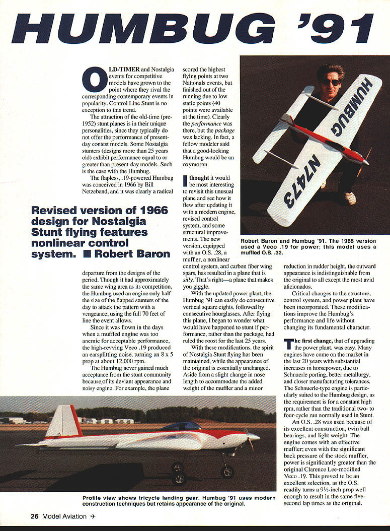
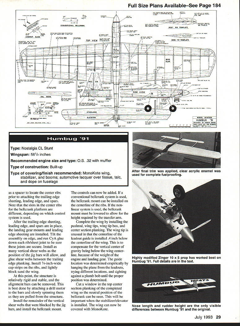
With these modifications, the spirit of Nostalgia Stunt flying has been maintained while the appearance of the original is essentially unchanged. Aside from a slight change in nose length to accommodate the added weight of the muffler and a minor reduction in rudder height, the outward appearance is indistinguishable from the original to all except the most avid aficionados.
Critical changes to the structure, control system, and power plant have been incorporated. These modifications improve the Humbug's performance and life without changing its fundamental character.
The first change, upgrading the power plant, was easy. Many engines have come on the market in the last 20 years with substantial increases in horsepower due to Schnuerle porting, better metallurgy, and closer manufacturing tolerances. The Schnuerle-type engine is particularly suited to the Humbug design, as the requirement is for a constant high rpm rather than the traditional two- to four-cycle run normally used in Stunt.
An O.S. .28 was used because of its excellent construction, twin ball bearings, and light weight. The engine comes with an effective muffler; even with the significant back pressure of the stock muffler, power is significantly greater than the original Clarence Lee–modified Veco .19. The O.S. readily turns a 9-1/2-inch prop well enough to result in the same five-second lap times as the original.
The O.S. .28 has since been superseded by the O.S. .32. The .32 is slightly heavier because the fins on the cylinder are larger; otherwise it is very similar. The .32 turns a larger-diameter prop than the old Veco .19 could, resulting in much greater thrust during maneuvers. This extra thrust enables the model to corner harder than the original while maintaining sufficient speed for a clean exit.
Tank setup and engine details:
- Run either conventional vent or Uniflo (muffler-pressure). Best runs were obtained using Uniflo.
- No-muffler-pressure runs simply required setting the engine just below maximum power.
- The engine runs hard as a two-cycle for the entire flight.
- Fuel: 10% nitro.
- Inlet diameter: .250 inch.
- Muffler exhaust opening enlarged from stock .250 inch to .270 inch.
- A .010 head gasket was used in addition to the stock gasket.
The greatest potential improvement after two decades of progress in construction techniques did not require drastic changes to some structures. The main spar in particular and the assembly sequence used the second time around are almost completely reversed from the original. The main structural problem with previous Humbugs was severe cornering loads that fatigued and broke the wooden wing spar after several hundred flights. I thought that additional torsional stiffness would improve stability in the wind.
I tried to use carbon tows running at 45° angles between the ribs to develop torsional stiffness, but I could not get a sufficiently reliable bond between the balsa and carbon fiber at the sheeting or at the ribs to be able to transmit loads into the fibers. I tried various brands of cyanoacrylate (CYA) glues and accelerators without success. Bonding unidirectional fibers with epoxy throughout the wing frame was too tedious, so I abandoned further attempts to incorporate carbon fiber into the structure.
After addressing the structural problems of the original Humbug and finding a suitable modern power plant/muffler combination, the next challenge was the control system.
One by-product of the exceptional performance of the original plane was that its control sensitivity for level flight and round maneuvers necessitated many hours of practice. This was not a stability problem—the Humbug was stable—but the control inputs necessary for level flight and round maneuvers were so subtle that it was hard to make minor corrections.
We designed a control system that slowed inputs for low control deflections (less than 10°) but allowed full control when needed for squares. Such a system was designed by Bill Netzeband ten years earlier and was incorporated into a revolutionary 1/2A stunter called the Barecatter.
Bill and I found that unless such a system was incorporated into a Humbug-type model, the airplane's performance would always have to be backed off because of the limitations imposed by the need to fly level and still be able to perform accurate round maneuvers. This nonlinear system, analogous to variable-ratio steering on an automobile, results in a dramatic improvement in the ability to fly level and execute round maneuvers without sacrificing the plane's ultimate performance in a square.
The 30% increase in the speed of the control system at the extremes of travel results in a corresponding 30% loss in mechanical advantage. This means that unless the control forces are kept light (through aerodynamic balancing or small moving surfaces), the system will be unable to generate enough torque for full travel of the controls.
Such is the case with a conventional flapped stunter—the high hinge moments required to actuate the flaps are too much for this control system to handle. It is important to remember that in a control line system only limited force is available. This force is limited to the line tension generated by the centrifugal force of the plane. Once the available force is used to overcome hinge moments, nothing remains to provide control effectiveness.
We eliminated the flaps and used a nonlinear bellcrank arrangement to provide reduced movement near neutral and increased movement near the extremes. This approach retains precise, small corrections for level and round flying while allowing full authority for square flying and aggressive maneuvers.
The transfer arm that provides the variable ratio is mounted below the rib centerline to clear the bellcrank and to simplify the slotting of the elevator horn. The geometry is arranged so that small handle movements around neutral produce small elevator deflections, and larger handle inputs progressively increase the elevator deflection per degree of handle movement. The system is simple, reliable, and perfectly suited to a model such as the Humbug that must be capable of both delicate round flying and aggressive square maneuvers.
If control deflection demands exceed what can be generated by the line tension, no additional deflection (hence, lift) can be obtained.
The system requires careful fitting and installation. The only way to accurately establish the critical slot and hole locations is by using a mill—the tolerances are too demanding for hand work. It is particularly important that the system be in the neutral position when the elevator is neutral, or the up and down control response will be significantly different.
In addition, the length of the control horn on the elevator does more than simply change the sensitivity at the handle. With this system, the length of the elevator control horn determines the maximum travel of the elevator and determines the extent that the nonlinear aspects of the system will be observed in the flight properties of the airplane. This differs from a conventional system in which elevator horn length changes only the relationship between handle movement and control deflection. From the standpoint of control sensitivity, changing the handle width in a conventional system has an effect identical to changing the horn length.
Because of the critical nature of horn length in relation to the rest of the control system, a slot was machined in the horn and the effective length made infinitely adjustable over the anticipated range. Adjusting horn length changes the maximum travel of the elevator until the cornering ability and associated speed loss through the corner are to your liking. The handle width is then altered to adjust sensitivity.
All of this adjusting is done after the center of gravity (CG) is positioned as per the drawings. For simplicity, a conventional control system (shown on the plans) can be substituted, but there will be some loss in performance for the reasons stated above.
CONSTRUCTION
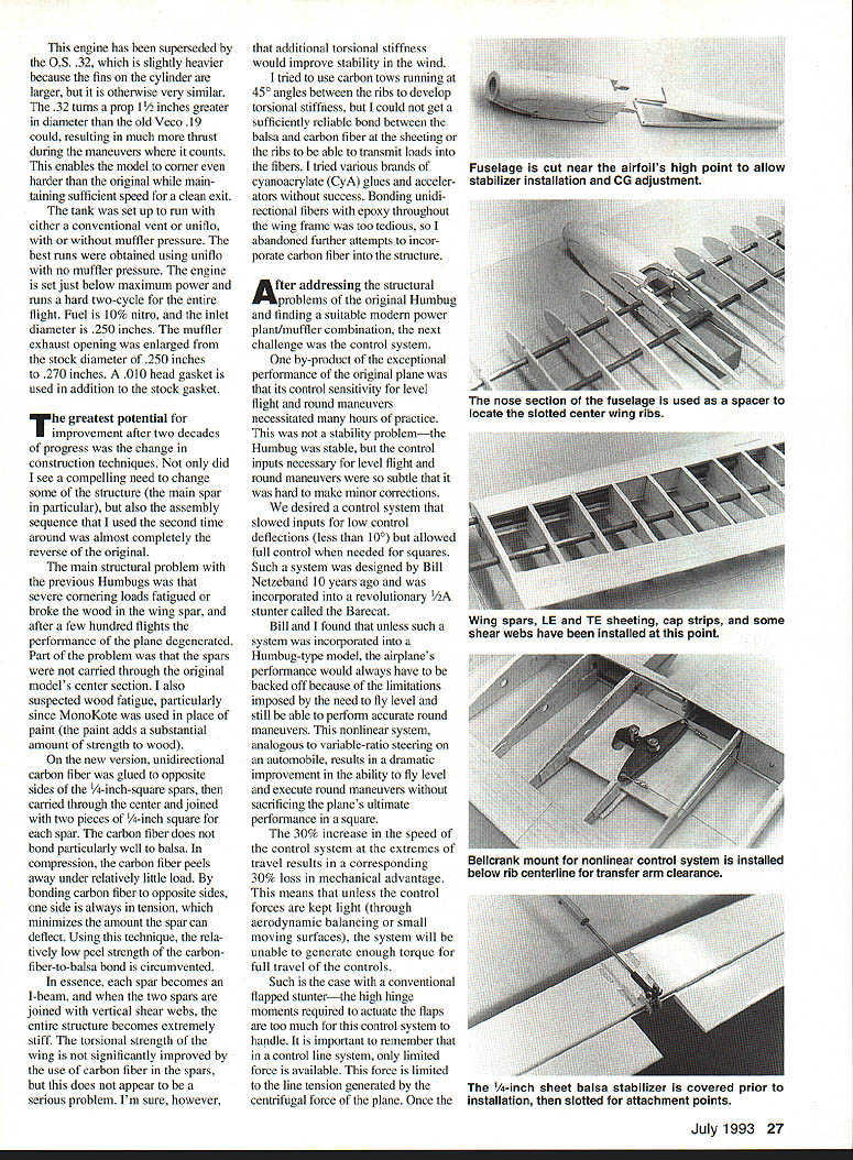
The fuselage is made first, since its exact width is needed to accurately locate the center ribs. The fuselage is made in one piece, as it would be on a conventional plane, then is cut in two near the high point of the wing. This is necessary to install the aft fuselage around the stabilizer (which is attached before the fuselage is added) and to allow the nose length to be altered to adjust the center of gravity.
With this construction, the nose can be sawed off in the center and still be made to fit to the wing and aft body. Depending on the engine/muffler combination used, the CG can be altered by adjusting the nose length, which minimizes ballast requirements.
The bottom block should be glued on permanently, while the top block should be tack-glued for removal when installing the aft fuselage around the stabilizer. Note that the cowling hold-down consists of two screws in the front, which tie into blind nuts located on a 3/32 plywood rim, and two screws in the side of the body, which tie into tabs on the cowling. The reason for the tabs is that there is no room for a more conventional attachment point at the rear of the cowling, since the tank vents, landing gear mount, and tank installation would interfere.
The bottom portion of the fuselage forward of the fuselage break is 1/8" Lite Ply with the grain running fore and aft to provide the nose gear mount. Underneath the plywood, 1/8" balsa with the grain running across the fuselage adds significant stiffness to the bottom with very little weight increase. Blind nuts are used in conjunction with nylon clips to fasten the nose gear. 1/8" aluminum plates are used under the engine to prevent denting of the bearers when the engine is bolted in.
Once the fuselage is complete, the wing construction can be started. The ribs are made by placing thirteen 3/32" sheets between 1/16" plywood templates, drilling precise 3/32" diameter holes, and installing a brass tube in each hole prior to carving the ribs to exact size. The holes in the ribs are best cut by a drill press and a sharpened piece of 1/8" brass tubing. A conventional drill bit will produce a very poor-quality hole when drilling through a stack of balsa.
The ribs are then marked so that they will be oriented on the jig bars the same way they were during the carving process. This cancels out any error introduced if the jig alignment holes are not exactly on the centerline of the ribs. After the ribs are made, the innermost and outermost ribs are traced and cut from 1/16" sheet balsa. These two ribs need to be made wider to facilitate construction and to provide additional strength.
The ribs are then slid onto the jig bars. The use of jig bars, demonstrated years ago by Al Rabe, is the most accurate way to construct a built-up wing. Not only does it work exceptionally well, but it does not increase construction time and actually makes the wing come together very easily.
Now it should be evident why the fuselage is constructed first. The two 1/4" sheet center ribs must be located to the exact fuselage width, since this will be an important glue join to attach the fuselage to the wing. Use the fuselage nose portion as a spacer to locate the center ribs prior to attaching the trailing edge sheeting, leading edge, and spars. Note that the slots in the center ribs for the bellcrank platform are different, depending on which control system is used.
After the trailing edge sheeting, leading edge, and spars are in place, the landing gear mounts and leading edge sheeting are installed. Tilt the assembly on edge, and run CYA glue down each rib/sheet joint to be sure these joints are secure. Install as many vertical shear webs as the position of the jig bars will allow, and glue shear webs between the trailing edge planking. Install 1/4"-wide cap strips on the ribs, and lightly block sand the wing.
At this point the structure is relatively rigid and stable, and the alignment pins can be removed. This is best done by attaching a drill motor to the bars and slowly spinning them as they are pulled from the structure.
Install the remainder of the vertical shear webs that were blocked by the jig bars, and install the bellcrank mount.
The controls can now be added. If a conventional bellcrank system is used, the bellcrank mount can be installed on the centerline of the ribs. If the nonlinear system is used, the bellcrank mount must be lowered to allow for the height required by the transfer arm.
Complete the wing by installing the pushrod, wing tips, wing tip box, and center section planking. The wing tip is unusual in that the centerline of the leadout guide is installed 0.4" below the centerline of the wing. This compensates for the vertical center of gravity being below the wing centerline because of the weight of the engine and landing gear. The guide location was determined empirically by hanging the plane from the leadouts, trying different locations, and sighting against a plumb bob until the proper position was determined.
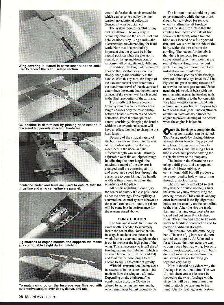
Cut a window in the top center section planking of the completed wing so the neutral position of the bellcrank can be seen. This will be important when the stabilizer/elevator is installed. The wing can now be covered with MonoKote.
The booms are made next by sandwiching a length of 1/32" plywood between two pieces of 3/16" balsa. This makes an extremely stiff and light boom (about 1/2 ounce). The MonoKote covering is wrapped around the edge where it joins the wing and is then cut away just enough to effect a good bond to the wing.
Cut away just enough MonoKote on the wing for a good glue joint—so that no bare wood is exposed outboard of the booms. The booms are then glued to the wing using a slow-curing epoxy, which gives time to accurately align them as well as to wipe away the excess glue with alcohol or thinner.
The stabilizer and elevator are made from 1/4" sheet balsa. These are covered with MonoKote prior to installation, cutting slots in the covering as per the booms. The stabilizer is now glued to the booms, taking care to locate them accurately relative to the wing. Note that the body is not glued at this time, but is placed into the wing as a reference for stabilizer alignment.
Now look in the window of the wing center section planking, and place the bellcrank in the neutral position. Tape the pushrod to the wing so it cannot move. The pushrod is attached to the elevator horn with the elevator temporarily held in place by the hinges (do not glue the hinges at this time). The clevis is adjusted until the elevator is neutral while the pushrod/bellcrank is maintained in the neutral position. At this point, release the tape from the pushrod and check the action of the controls.
Remove the top block of the rear portion of the fuselage and install the aft body around the stabilizer, taking care not to put any load on the stabilizer. Cut slots in the MonoKote to attach the rear fuselage to the wing. Glue the top block on, and cut the slot for the fin.
At this point the nose portion of the fuselage can be pinned in place, and the center of gravity can be determined by installing all of the hardware. If the plane is nose heavy, the fuselage can be cut in the center section and shortened until the proper center of gravity is approximately 1/8" in front of the position shown on the plans. The weight of the fillets and paint will shift the center of gravity slightly aft.
If the entire plane is painted rather than covered with MonoKote, you will have to estimate the weight of the paint and its effect on the center of gravity to determine the nose length that will require minimum ballast. Glue the fuselage with a slow-curing epoxy, using a Robart incidence meter in conjunction with a bubble level to ensure that the thrustline is parallel to the wing centerline. Glass the nose using 3/4-ounce cloth and epoxy. The fin can be permanently glued to the fuselage and the canopy added to complete the framing of the aircraft.
The fuselage can be painted per your favorite finishing technique. For my model, standard dope, tissue, and tail finish was used to fill the grain. Since none of the commercial modeling dopes are a good match to white MonoKote, I used automotive lacquer. After trim, the paint and canopy can be sealed with Ditzler acrylic enamel to completely fuel-proof the finish.
When applying the final clear coat, it is recommended that the masking tape be placed slightly outside the fillet so the enamel can run around the edge of the fillet and seal the edge. I use 3M fine line tape for masking, as it gives a clean edge and leaves no residue when it is removed. Remember to pull the tape off while the enamel is still tacky to prevent bonding the tape to the plane and to allow the enamel to seal the edge.
During all finish work—including doping, applying paper, fillets, spraying, and masking—I use a jig that attaches to the engine mounts and suspends the plane at a comfortable height. Complete paint trim, rudder and elevator hinging, and landing gear installation while the plane is held in the jig.
FLYING AND TRIMMING
Since the Humbug has no flaps, it is easier to adjust than a conventional stunter. First, install any ballast required to position the center of gravity as shown on the plans. From a stability standpoint, the plane will tolerate a more aft center of gravity, but line tension is not positive under varied conditions if the CG is aft of the position shown on the plans. Set the leadouts for each line as shown on the plans.
Test flights should be on short lines (62–64 feet x .015) for safety. Once the model is trimmed out, 65–68 feet is optimum. Place approximately 3/4 ounce of weight in the tip tank. Adjust the elevator horn to provide 25° of travel in each direction. I started with a four-inch-wide handle.
As with all stunters, prop selection is critical. It is amazing how that little piece of wood can affect flight performance. I prefer wood props—they are readily modified, and their light weight keeps precession to a minimum.
To get the most from this or any stunt plane, a pitch gauge is a must. Not only can you make the blades more accurate with a pitch gauge, you can also determine exactly which way you need to adjust pitch to obtain the desired performance.
In general:
- The lower the pitch, the greater the vertical capability, provided the engine can turn the prop fast enough to give adequate airspeed.
- Increasing the pitch will increase airspeed, but will also increase the tendency to whip up in windy conditions.
- Increased diameter also increases vertical capability, but at a cost of increased whip-up in wind.
- Changing blade shape alters power requirements, but may not cause a corresponding change in airspeed or thrust.
Finding the trade-off between diameter, pitch, and blade shape is a challenge.
For the Humbug '91, here are the dimensions of my best prop to date:
- Start with a Zinger 10 x 5 (measured pitch 4.6 to 5 inches).
- De-pitch to a true 4.0 inches at all stations.
- Cut the diameter to 9-1/2 inches, using dial calipers to exactly measure each blade's length.
- Carve a sweep in the leading edge starting approximately 1 inch from the tip, ending in a tip diameter of about 1/8 inch.
- Balance the blades to minimize vibration.
Carefully check your flying site for the presence of small rocks. Even with tricycle landing gear, the thin prop turning at high rpm can easily be broken, leading to a shaft run that can damage the airframe.
Set the engine to a hard two-cycle, but clearly off maximum power. With the 9-1/2 x 4 prop, lap times should be 4-3/4 to 5 seconds. Check that the wings are level in both upright and inverted flight. If one wing is high, steam the wing over a kettle of boiling water until the model flies level, both upright and inverted.
I found that while the wing was obviously in need of steaming based on initial flights, the warp was not readily detected by sighting down the trailing edge. In any event, steam the wing in the direction indicated by the attitude of the plane in level flight. If the wing is high in both directions, add tip weight; if low in both directions, remove weight.
Next make sure the engine is running the same in both attitudes. Checking lap times both upright and inverted is a good way to determine if the tank needs trimming. If the plane is slower right-side-up than inverted, shim the tank down until lap times each way are close to equal.
Once the above steps have been completed, final trimming is a matter of adjusting the control travel to trade off cornering against loss of airspeed, then adjusting handle width to suit your needs. I ended up with 22° of elevator travel. Minor adjustments to leadout rake can be made by adjusting the up line to improve inside maneuvers and the down line for outside maneuvers.
Small changes in prop diameter (1/8 inch at a time) will result in tighter, slower corners as the diameter is decreased, with the opposite effect as diameter is increased. As with any high-performance vehicle, very small adjustments have significant effects on flight characteristics. A 1/8-inch change in leadout rake or a few millimeters change in airspeed will be readily noticed at the handle. With many possible adjustments, a very wide range of performance and handling characteristics is available to the flier.
The Humbug will utilize all your trimming and flying skills. On one hand, it can be trimmed to fly like a trainer; on the other, it can be trimmed to deliver performance to tax the most experienced pilot. You make the choice!
Transcribed from original scans by AI. Minor OCR errors may remain.

