
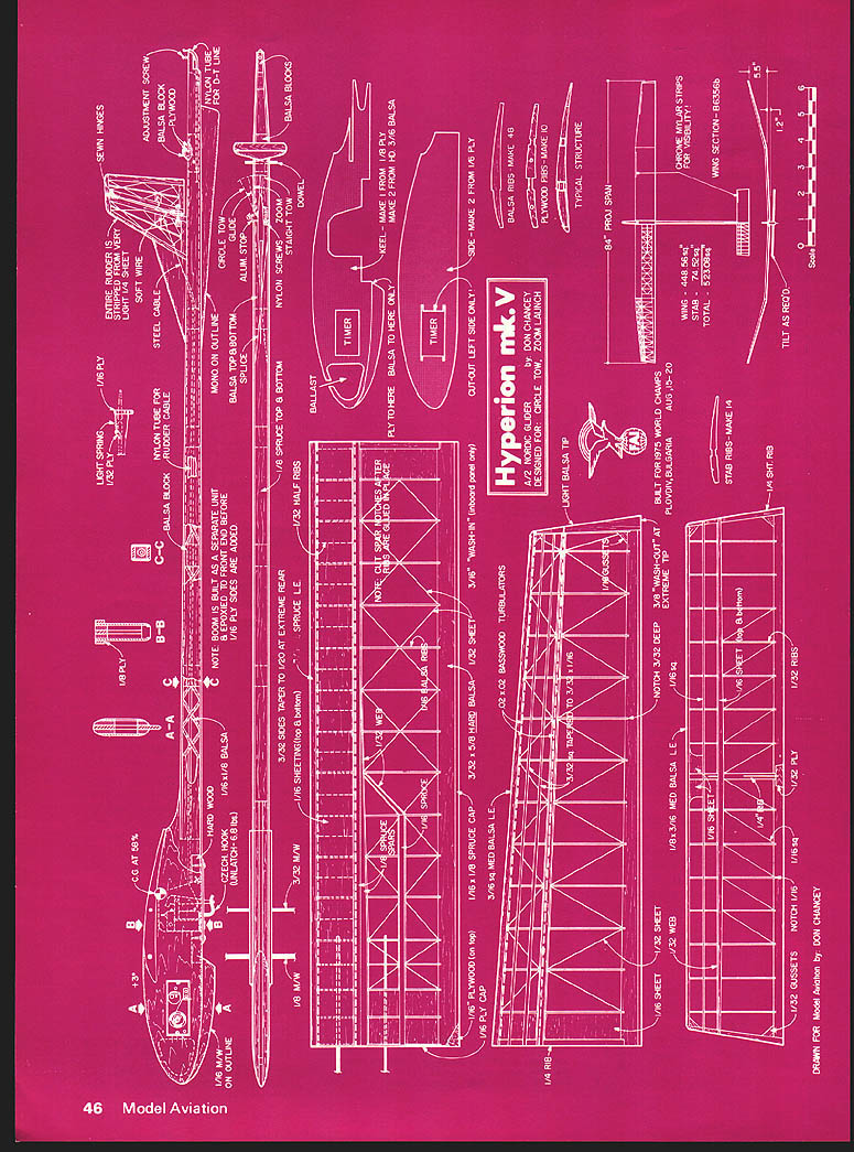
Hyperion mk. V
Designed—by a member of the U.S. 1975 Nordic team—for circle tow and zoom launch this glider incorporates the latest practice.
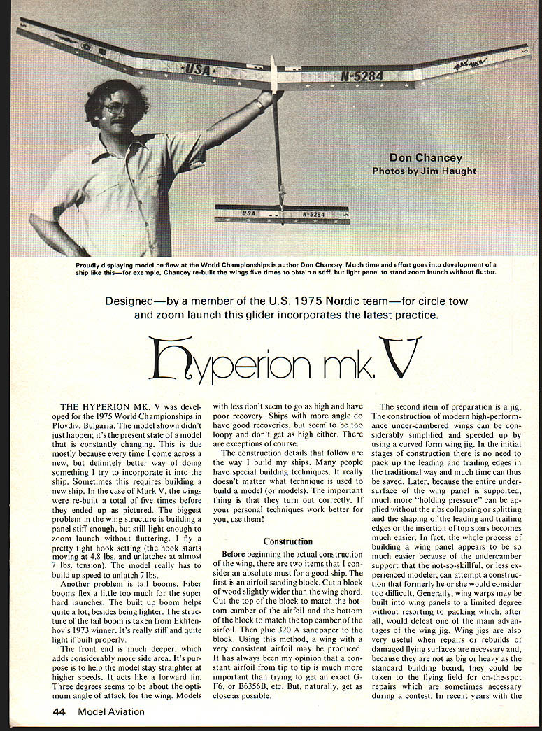
THE HYPERION MK. V was developed for the 1975 World Championships in Plovdiv, Bulgaria. The model shown didn't just happen; it's the present state of a model that is constantly changing. This is due mostly because every time I come across a new, but definitely better way of doing something I try to incorporate it into the ship. Sometimes this requires building a new ship. In the case of Mark V, the wings were re-built a total of five times before they ended up as pictured. The biggest problem in the wing structure is building a panel stiff enough, but still light enough to zoom launch without fluttering. I fly a pretty tight hook setting (the hook starts moving at 4.8 lbs., and unlatches at almost 7 lbs. tension). The model really has to build up speed to unlatch 7 lbs.
Another problem is tail booms. Fiber booms flex a little too much on super hard launches. A built-up boom helps quite a lot besides being lighter structurally. The tail boom is taken from Ekhtenhov's 1973 winner. It's really stiff and quite light if built properly.
Its front end is much deeper, which adds considerably more side area. Its purpose is to help the model stay straighter at higher speeds; it acts like a forward fin. Three degrees seems to be about the optimum angle of attack for the wing. Models with less don't seem to go as high and have poor recovery. Ships with more angle do have good recoveries, but seem to be too loopy and don't get as high either. There are exceptions of course.
The construction details that follow are the way I build my ships. Many people have special building techniques. It really doesn't matter what technique is used to build a model (or models). The important thing is that they turn out correctly. If your personal techniques work better for you, use them!
Construction
Before beginning the actual construction of the wing, there are two items that I consider an absolute must for a good ship. The first is an airfoil sanding block. Cut a block of wood slightly wider than the wing chord. Cut the top of the block to match the bottom camber of the airfoil and the bottom of the block to match the top camber of the airfoil. Then glue 320 sandpaper to the block. Using this method, a wing with a very consistent airfoil may be produced. It has always been my opinion that a constant airfoil from tip to tip is much more important than trying to get an exact G, F6, B6356B, etc. But, naturally, get as close as possible.
The second item of preparation is a jig. The construction of modern high-performance under-cambered wings can be considerably simplified and speeded up by using a curved-form wing jig. In the initial stages of construction there is no need to pack up the leading and trailing edges in the traditional way and much time can thus be saved. Later, because the entire under-surface of the wing panel is supported, much more "holding pressure" can be applied without the ribs collapsing or splitting and the shaping of the leading and trailing edges or the insertion of top spars becomes much easier. In fact, the whole process of building a wing panel appears to be much easier because of the undercamber support. The not-so-skillful, or less experienced modeler, can attempt a construction that formerly he or she would consider too difficult. Generally, wing warps may be built into wing panels to a limited degree, but resorting to packing, which, after all, would defeat one of the main advantages of the wing jig. Wing jigs are also very useful when repairs or rebuilds of damaged flying surfaces are necessary and, because they are not as big or heavy as the standard building board, they could be taken to the flying field for on-the-spot repairs which are sometimes necessary during a contest. In recent years with the advent of quick-drying epoxies, complicated field repairs are possible; a jig will certainly prove beneficial.
Construction of Wing Jig (Aero Modeller)
Draw the airfoil full size as accurately as possible. Using the undercamber portion only, carefully draw tangents at the leading and trailing edges so that a smooth continuous line is produced, and extend them 1/2" at the front and rear of the airfoil so that the width of the baseboard is determined. The length of the baseboard is such as to accommodate the longest length of wing panel likely to be assembled over the jig. Something around 30" is normal. Having determined the dimensions of the baseboard, it must now be cut to size from 3/4" block board, clipboard or similar, but make sure that whatever material is used it is perfectly flat.
Using a set square, mark off the locations of the ribs allowing a uniform spacing of about 2" or 2-1/2" between ribs and then mark the locations of any webbing. Carefully make a plywood rib template and make sufficient ribs with it from 1/8" medium balsa sheet. When they are all cut out, pin them together and sand them to ensure they all have an identical profile. Epoxy the ribs to the baseboard in the marked off locations. The next stage is to epoxy into place all the webs. These are made from 1/4" medium balsa sheet and are located at the leading and trailing edges and intermediates along the chord to give about 2 to 2-1/2" gaps. Make the webs slightly oversize in the vertical direction and when the epoxy is set plane or sand them to the correct camber flush with the ribs.
Next cut a piece of 1/16" thick plywood slightly oversize to fit over the top of the assembled structure. Cover the structure with contact cement and attach the plywood top using rubber strips or weights to hold it down until the epoxy sets. When all is dry remove the rubber strip or weights and trim the plywood to size. Finally give the jig four or five coats of dope, rubbing down between each coat with 600 grade wet and dry paper, and complete with two or three coats of car or floor wax polish.
Wing: Make the plywood center ribs first, making sure they are well exactly the same and that the holes line up. Spar notches are cut before assembly in the plywood ribs only. Next, cut the main ribs for the center panels from 8-10 lb. C-grain 1/16" sheet. Cut the main ribs for the tips from slightly lighter material. Select a good hard piece for the balsa portion of the trailing edge, and epoxy it to the spruce portion (the spruce cap on the rear of the T.E. is an absolute necessity with the thin airfoils of today). Do most of the shaping and notch the T.E. before assembly. Pin the L.E., and T.E., and bottom sheeting in place on the jig. Position the plywood root ribs and tack in place with epoxy. (Note: best results come from building center panels end to end. Tubing is cut in two after complete assembly of wing.)
Now glue in all main ribs and allow to dry. Using a straight edge, mark and cut notches for all top spars. Install top spars, sheeting, etc. Allow to dry while still on jig. After this is thoroughly dry, remove the wing from the jig and do the same for the bottom. Next, add the webbing to the spars, the remainder of the sheeting and the cross ribs. The cross ribs are cut slightly oversize and sanded to shape after assembly with the airfoil block. The tips can now be assembled on the jig with the leading edges straight. Due to the taper and the airfoiled jigs, this will automatically "build in" the required amount of wash out.
Dihedral angles may be sanded into the 1/4" "top of ribs" by propping the wing up to the desired angle and sanding with a flat sanding block "hand launch glider" style. Finish sanding the entire wing with 400-A sandpaper. At this point I apply a total of five coats of 60-40 dope to the entire structure. This serves a dual purpose. First it insures that the tissue will stick to every part of the structure it touches, and secondly it is especially helpful in weather proofing the wood. Models done this way will last for several years of flying. Allow the structure to dry thoroughly and cover with Japanese tissue.
Monokote does not give the proper rigidity required for zoom launching, plus the fact that it is just too slick. The slick surface definitely reduces the glide. (Bob White is using a flannel in his dope to roughen up the flying surfaces — an obviously successful attempt to make the air stick to the airfoils better.) The bottom of the center panels should be double-covered to help cut down on punctures. (Note: I don't remember seeing one single airplane at the World Champs that was Monocoated; that's in all 3 events.) Apply several coats of dope and allow to dry thoroughly. Add
Hyperion mk. V
Designed by Don Chancey — for circle tow, zoom launch
Built for the 1975 World Championships, Plovdiv, Bulgaria
Drawn for Model Aviation by Don Chancey the turbulators and set up to cure while you finish the rest of the model.
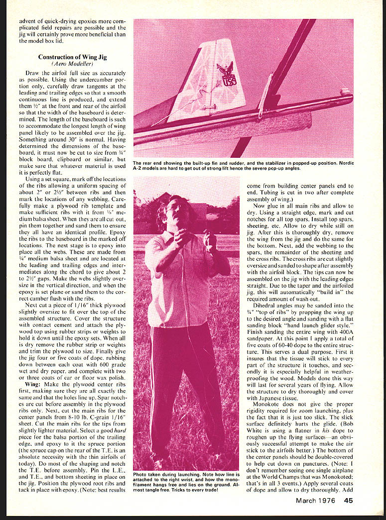
Stab and Rudder: Carefully select the wood for the rudder/fin and stabilizer. Lightness is a virtue, but don't build too flimsy. I hear talk of 7- to 10-gram stabs and people just turn green with envy. A stab that light is not necessary (the 1975 World Champion's stabs weigh almost 12 grams). I recommend building a substantial stab of 10 to 12 grams. You can make up for the extra weight elsewhere on the tail end. The built-up rudder can save 1 to 2 grams if built properly. The wood for my rudders is all stripwood from 1/4" sheet. Use 4-lb. stock when possible. After construction, coat the entire rudder with "Hot-Stuff." This will yield a rudder that is extremely light yet very tough. Coat the framework of the rudder and stab with three thin coats of clear dope and cover with Japanese tissue. About three coats of dope over the tissue is fine. Set this aside and allow to cure.
Fuselage: If you want to build an all-out serious model and do not have access to materials for making large diameter fiberglass tube, the built-up balsa and spruce tail boom is the best way to go. It can be built much easier than a rolled balsa tube. The ones that I built turned out extremely stiff (much more so than a fiber boom). My built-up booms are not only stiffer, but also 4 to 6 grams lighter than a comparable length fiber tube.
Cut the sides for the tail boom from stiff but light 3/32" sheet. I use "C" grain, because that's what I use almost everywhere. Make sure both sides match exactly. Sand the sides so that they taper from 3/32" thick at the front to 1/32" at the extreme rear. Pin the two sides to a flat board and add the square blocks and geodetic bracing. To avoid excess pulling, and especially excess weight from glue build-up, the entire aft end of my ships (from rear of wing back) is built with "Hot-Stuff."
Build-up the tail boom as a separate unit. After the front end is constructed to a certain stage the boom is just plugged in place and epoxied there. Be sure to make provisions for the braided steel auto-rudder cable.
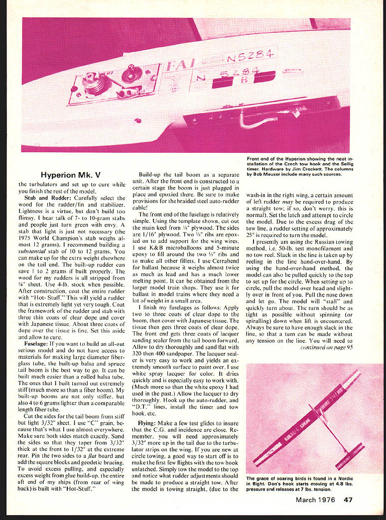
The front end of the fuselage is relatively simple. Using the template shown, cut out the main keel from 1/8" plywood. The sides are 1/16" plywood. Two 1/8" ribs are epoxied on to add support for the wing wires. I use K & B microballoons and 5-minute epoxy to fill around the two 1/8" ribs and to make all other fillets. I use Cernarenda for ballast because it weighs almost twice as much as lead and has a much lower melting point. It can be obtained from the larger model train shops. They use it for ballast in model trains where they need a lot of weight in a small area.
I finish my fuselages as follows: Apply two to three coats of clear dope to the boom, then cover with Japanese tissue. The tissue then gets three coats of clear dope. The front end gets three coats of lacquer sanding sealer from the tail boom forward. Allow to dry thoroughly and sand with 320 then 400 sandpaper. The lacquer sealer is very easy to work and yields an extremely smooth surface to paint over. I use white spray lacquer for color. It dries quickly and is especially easy to work with. (Much more so than the white epoxy I had used in the past.) Allow the lacquer to dry thoroughly. Hook up the auto-rudder, and "D.T." lines, install the timer and tow hook, etc.
Flying: Make a few test glides to insure that the C.G. and incidence are close. Remember, you will need approximately 3/32" more up in the tail due to the turbulator strips on the wing. If you are new at circle towing, a good way to start off is to make the first few nights with the tow hook unlatched. Simply tow the model to the top and notice what rudder adjustments should be made to produce a straight tow. After the model is towing straight, (due to the wash-in in the right wing, a certain amount of left rudder may be required to produce a straight tow; if so, don't worry, this is normal). Set the latch and attempt to circle the model. Due to the excess drag of the tow line, a rudder setting of approximately 25° is required to turn the model.
I presently am using the Russian towing method, i.e., 50-lb. test monofilament and no tow reel. Slack in the line is taken up by reeling in the line hand-over-hand. By using the hand-over-hand method, the model can also be pulled quickly to the top to set up for the circle. When setting up to circle, pull the model overhead and slightly out in front of you. Pull the nose down and let go. The model will "stall" and quickly turn about. The turn should be as tight as possible without spinning (or spiralling) down when lift is encountered. Always be sure to have enough slack in the line, so that a turn can be made without any tension on the line. You will need to to pull tension at the proper point in the circle to build up speed for the launch, etc. Because of the stretchiness of the monofilament line, the model will continue to slack slightly after tension is applied. It is better to have a little extra speed than none at all. Once you have mastered the circle the launch is simply a matter of timing. Pull the model up on the circle and when the line is vertical, give a quick snap-down on the stick while holding the model firmly with the other hand. This will produce the desired zoom launch.
THE HYPERION MK V developed 1975 World Championships Plovdiv, Bulgaria. The model shown didn't just happen; its present state is the result of constant changes, due mostly to the times I come across a new, definitely better way of doing something and try to incorporate it. Sometimes this requires building a new ship. In the case of the Mark V wings, they were re-built a total of five times before I ended up with the pictured version. The biggest problem in wing structure is building the panel stiff enough yet still light enough for zoom launch without fluttering and to fly with a pretty tight hook setting. The hook starts moving at .48 lbs, unlatches almost 7 lbs tension; the model really has to build up speed to unlatch 7 lbs.
Another problem was tail booms. Fiber booms flexed a little too much on super hard launches. A built-up boom helps quite a lot besides being lighter. The tail boom design was taken from Ektenhov's 1973 winner. It's really stiff and quite light if built properly. The front end is much deeper and adds considerable side area. Its purpose is to help the model stay straighter at higher speeds, acting like a forward fin.
Three degrees seems about the optimum angle of attack on the wing. Models with less don't seem to go high and have poor recovery. Ships with more angle have good recoveries but seem too loopy and don't get high either. Of course, construction details follow the way I build ships. People have special building techniques and it really doesn't matter what technique is used to build models; the important thing is that they turn out correctly. Use personal techniques that work better for you.
Construction
Before beginning actual construction of the wing two items I consider absolute musts for a good ship. First, an airfoil sanding block. Cut a block of wood slightly wider than the wing chord. Cut the top block to match the top camber airfoil and the bottom block to match the bottom camber airfoil. Glue 320-grit sandpaper to the block. Using this method a very consistent airfoil may be produced. I have always been of the opinion that a constant airfoil tip-to-tip is much more important than trying to get exact G, F, 6, B, etc.; naturally get as close as possible.
The second item is a preparation jig for construction. Modern high-performance under-cambered wings can be considerably simplified and speeded up using a curved-form wing jig. In the initial stages of construction there is no need to pack up leading and trailing edges in the traditional way. Much time can thus be saved. Later, because the entire undersurface of the wing panel is supported, much holding pressure can be applied without ribs collapsing or splitting. Shaping leading and trailing edges and insertion of top spars becomes much easier. In fact, the whole process of building a wing panel appears much easier because the undercamber support is provided; a less skillful, less experienced modeler can attempt construction formerly considered too difficult. Generally, wing warps may be built into wing panels to a limited degree without resorting to packing; doing so would defeat the main advantages of the wing jig. Wing jigs are also very useful for repairs and rebuilds of damaged flying surfaces. They are necessary because a big heavy standard building board could be taken to the flying field for on-the-spot repairs sometimes necessary during contest days. In recent years with the advent of quick-drying epoxies, complicated field repairs are possible; a jig will certainly prove beneficial.
Construction — Wing Jig
Draw the airfoil full size as accurately as possible. Using the undercamber portion, carefully draw tangents to the leading and trailing edges to produce a smooth continuous line. Produce and extend the rear airfoil width on the baseboard. The baseboard length should accommodate the longest wing panel likely to be assembled over the jig—something around 30" is normal.
Having determined the dimensions of the baseboard, cut it to size from hardboard or clipboard or similar; make sure whatever material used is perfectly flat. Using a set square mark off locations for ribs allowing uniform spacing of about 2½" between ribs. Mark locations for webbing. Carefully make a plywood rib template. Make sufficient ribs from balsa sheet, cut out, pin together and sand to ensure they have identical profile. Epoxy ribs to the baseboard at the marked locations. The next stage is filament the model can be tugged and pulled at without prematurely unlatching the hook. The same hook tension can be flown in all conditions. (Starts moving at 4.8 lbs. and unlatches at almost 7 lbs.) The stretchy line makes thermal flying much better. A no-stretch line should be used in calm, no-lift situations. Conditions should be compensated for by changing the towline and not by readjusting the tension of the towhook.
The only real reason for accidentally coming unlatched is a lack of practice. I won't try to explain all the details of circle towing here. Most won't make a lot of sense anyway until you've tried it. If you have any questions feel free to ask. Best of luck with the model and remember, there is absolutely no substitute for practice! Practice until towing is second nature. The only thing you should have to worry about when on the line is finding a thermal.
Transcribed from original scans by AI. Minor OCR errors may remain.

