
IceBox 25
John Oldenkamp
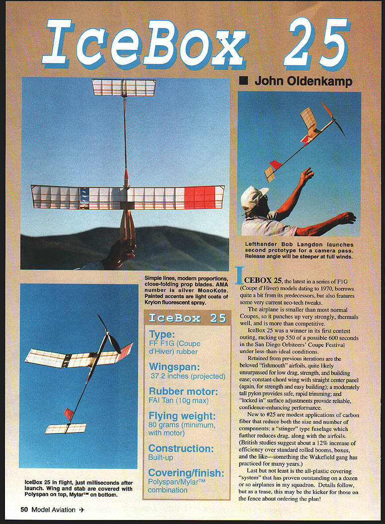
ICEBOX 25, the latest in a series of F1G (Coupe d'Hiver) models dating to 1970, borrows quite a bit from its predecessors while adding several current neo-tech tweaks. The airplane is smaller than most normal Coupes, so it climbs strongly in thermals and is more than competitive. IceBox 25 won in its first contest outing, scoring 550 of a possible 600 seconds in the San Diego Orbiters' Coupe Festival under less-than-ideal conditions.
Retained from previous iterations are the beloved “fishmouth” airfoils—excellent for low drag, strength, and ease of building; a constant-chord wing with straight center pylon for strength and simple construction; a moderately tall pylon for safe rapid trimming; and “locked-in” surface adjustments for reliable, confidence-enhancing performance.
New to #25 are modest applications of carbon fiber that reduce both the size and number of components; a “stinger” type fuselage to further reduce drag; and an all-plastic covering system that has proven outstanding on a dozen or so squadron airplanes. British studies suggest the stinger/boom approach yields about a 12% increase in efficiency over standard rolled booms and boxes—an approach the Wakefield crowd has long practiced.
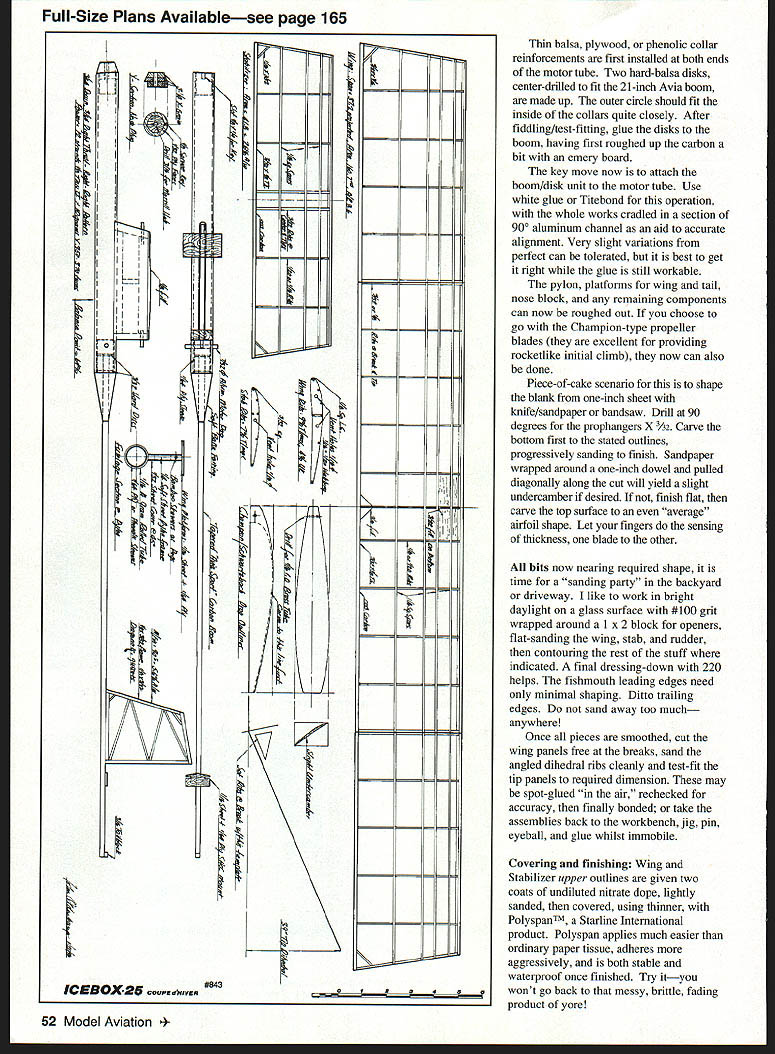
Full-size plans available—see page 165.
IceBox 25 (boxed data)
- Type: FF F1G (Coupe d'Hiver) rubber
- Wingspan: 37.2 inches (projected)
- Rubber motor: FAI Tan (10 g max)
- Flying weight: 80 grams (minimum, with motor)
- Construction: Built-up
- Covering/finish: Polyspan/Mylar combination
Construction
First-time builders should arrange a bit of mentoring from someone familiar with Coupe-class construction and the drawing. IceBox is a relatively puzzle-free build and can be completed in an average workshop in three days or less. Success requires careful selection of wood, access to an accurate gram scale, and economical use of thin cyanoacrylate (CyA) glue. Plasti-Stic CyA is recommended for general use and particularly for carbon-to-balsa bonds. See the supplier list at the end for sourcing.
Select sheet and stripwood for low weight and strength:
- Rib stock: 9–12 g per sheet, quarter-grain preferred.
- Motor-tube material: A-grain, about a 10 g starter sheet.
- Sticks: whippy; medium-hard to hard for leading edges and main spars.
- Pylon frame: medium-soft.
- Platforms and ancillaries: medium (capped plywood where indicated).
Carbon strip should be cut from sheets sanded lightly and wiped clean with MEK (methyl ethyl ketone) or dope thinner prior to laying up frames. Trace rib templates with complete spar notches and cut from thin plywood. Cutoff pins help register parts during production. Cover the plan top and bottom with waxed paper and position on a level, pin-accepting surface such as Celotex.
Build rudder, stabilizer, and wing as flat as possible so parts fit closely with no residual stresses that might later cause warps. Lay structures down fully with pins trapping major elements; apply Plasti-Stic glue right to left. When locating and pinning trailing edges, pull the vertical-facing carbon strip along to create a good bond. As rib ends are glued in place the carbon will adhere between the nubs. After curing, remove the structure from the building surface and final-glue between-rib areas in the air. Repeat this approach for bottom spars, stick gussets, various sheet elements, and full-span wing spar webbing (note: webbing grain runs spanwise).
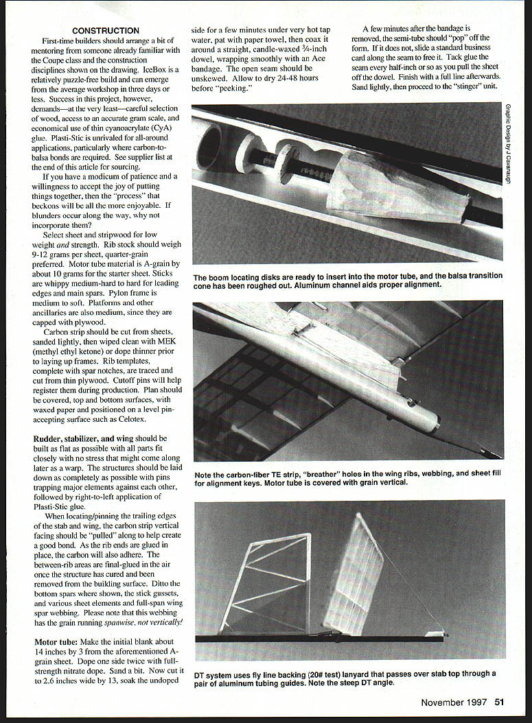
Thin balsa, plywood, or phenolic collar reinforcements are installed at both ends of the motor tube first. Make two hard-balsa disks center-drilled to fit the chosen boom (e.g., Avia boom). The outer circle should fit the inside of the collars closely. After test-fitting, glue the disks to the boom, lightly roughening the carbon with an emery board first.
Attach the boom/disk unit to the motor tube with white glue or Titebond, cradling the assembly in a section of 90° aluminum channel for alignment. Slight variations are tolerable, but it is best to get alignment accurate while the glue is workable.
Rough out the pylon, wing and rail platforms, nose block, and remaining components. If using Champion-type propeller blades (excellent for rocket-like initial climbs), shape the blanks now.
Shaping and sanding
- Shape prop blades from 1/8" or 1" sheet as indicated, drill prop-hanger holes at 90° (3/32"), and carve to outline. Use a dowel and sandpaper to produce slight undercamber if desired.
- Finish all parts with progressive sanding: start flat with #100 grit on a block, contour where indicated, then finish with 220 grit.
- Fishmouth leading edges and trailing edges need minimal shaping—avoid removing too much material.
Join wing panels at the breaks and sand dihedral ribs cleanly. Test-fit tip panels to required dimensions; they may be spot-glued in the air, rechecked, then finally bonded, or assembled on the bench with jigs and pins.
Motor tube
Make an initial blank about 14 inches long from the A-grain sheet. Dope one side twice with full-strength nitrate dope and sand lightly. Cut the sheet to length, soak the undoped side a few minutes under very hot tap water, pat with a paper towel, and coax it around a straight, candle-waxed 3¼-inch dowel, wrapping smoothly with an Ace bandage to keep the seam unskewed. Allow to dry 24–48 hours before checking. A few minutes after removing the bandage, the semi-tube should pop off the form; if it sticks, slide a business card along the seam to free it. Tack-glue the seam about ½ inch, pull the sheet off the dowel, finish the full seam afterward, sand lightly, and proceed with the stinger unit.
Install thin collars at both ends of the motor tube, fit the balsa disks into the boom, and finish the motor-tube/balsa transition cone as shown on the plan. An aluminum channel can aid alignment. Note the carbon-fiber trailing-edge strip, breather holes, wing ribs, webbing sheet fill, and alignment keys. Cover the motor tube with grain vertical to the centerline/thrustline.
The DT (dethermalizer) system uses flyline backing; a 20 lb test lanyard passes over the stabilizer top through a pair of aluminum tubing guides. Note the relatively steep DT angle; final DT angle recommended is about 60° for pop-up deployment.
Covering and finishing
- Prepare surfaces:
- Coat wing and stabilizer upper outlines with two coats of undiluted nitrate dope and sand lightly.
- Cover upper surfaces with Polyspan (Starline International product):
- Polyspan applies easier than tissue, adheres aggressively, and is stable and waterproof once finished.
- Try to get it reasonably smooth; trim excess with a new razor blade.
- Do not dope or fully finish yet. Turn the surfaces over and cover the bottom of the wing and stabilizer, and both sides of the rudder, with adhesive-backed iron-on .0015" Mylar (Model Research Labs).
- Attach with low heat on a Monokote or equivalent covering iron.
- Tack at mid-rib ends, corners, then midpoints lengthwise; gentle tugs help smooth the film after tacking.
- Iron each undercamber line fully—this takes a bit of practice but is manageable.
- The method aims to preserve optimum airfoil performance: the bottom surface is kept as smooth as possible while the upper surface remains slightly nap‑like and self-turbulating (classic Lippisch style). The result is a stable, puncture-resistant finish that tissue cannot match.
- Motor tube: apply a couple coats of nitrate (thinned 50%) before covering with Polyspan with grain vertical. Seal the seam with more dope, then spray two light coats of Deft semi-gloss Clear Wood Finish (contains lightweight fillers). Treat pylon, platforms, noseblock, prop blades and other parts similarly and sand to smooth.
- While these parts dry, apply two water-thin coats of nitrate to wing and stabilizer upper areas. Then shrink the coverings top and bottom using medium-high heat on the covering iron, working slowly and shuttling back and forth on the Polyspan and Mylar. If warps occur, apply opposite twist while shrinking to remove them. Small warps or offsets can also be induced or removed intentionally with heat and twist.
Other finishing steps
- If wrinkles appear on the motor tube covering, heat-shrink carefully.
- Mask off areas for color accents and spray very light coats of Krylon paint (two very light coats), then Krylon Crystal Clear. For a more durable, professional finish, follow with Behlen Hard Gloss Polyurethane when time permits.
- Add AMA numbers (vinyl press-on), owner labels, club decals, etc.
Final assembly
- Attach the stabilizer mount, wing platforms, and rudder in proper locations. Allow for 1/2" tilt in the stabilizer for right glide turn (right side of stabilizer higher than left when viewed from the rear).
- Prepare the motor peg, DT hardware (lanyard-over-stabilizer-from-front-fuse system preferred), a 10 g motor, prop and noseblock assemblies.
- Because of the short nose moment, a Montreal-stop front end is recommended; John Morrill designs are dependable and economical.
- Propellers: store-bought blades are available; the Champion unit illustrated provides excellent climb performance.
Assembly and balance:
- Install a twelve-strand 10 g motor with Crockett hook up front and fit prop blades to the hub/noseblock.
- Band the wing and stabilizer to their platforms.
- Tape the pylon/wing to rough location as shown on the plan and suspend the airplane (with blades folded) to establish the trial balance point.
- Adjust the pylon fore-aft until proper level suspension occurs with the balance point at about 64% of wing chord. Mark the pylon position fore and aft, roughen through the covering with emery board, then retape the pylon (without the wing), align with rudder and thrustline, tack-glue both pylon ends, remove the tape, and finish with a full-length bead of Plasti-Stic CyA.
Preflight checks:
- Ensure proper right and down thrust as shown on the plan—these are essential.
- Confirm approximately 1/8" incidence between wing and stabilizer.
- Verify prop blades fold flat and noseblock key seats firmly.
- Test that the pop-up DT function is friction-free, at correct angle (≈60°), and deploys quickly.
Trimming and flying
- Start trimming on a calm morning. Use a few test glides and add or subtract incidence with index-card shims.
- First flight: use about 33% turns (or 125 turns on the counter). Launch level into the drift—do not shove it steeply up.
- Observe for a smooth right turn under power, precise prop stop and fold, and correct right glide. Initial stalls may indicate the need for downthrust or slightly less incidence—but not both at once.
- Always install and light the DT fuse even in low winds.
- Enlist an experienced observer during testing to help interpret subtle flight behaviors.
- At full power, IceBox 25 will accelerate almost vertically then settle into a strong cruise, especially in thermals. Its small proportions give top competitive performance in moderate conditions, though it is not an extreme light-air machine. Consider a longer-wing version for early-morning light-air work.
If you have machine-shop skills, a removable tailboom, two-piece wing, and associated hardware would be useful improvements. As built, IceBox 25 is a very pleasing design; the challenge is learning air-picking, changing motors before each flight, and pushing performance against rivals.
Questions and assistance are welcome at my hangar or by telephone.
John Oldenkamp 1625 Fern St. San Diego, CA 92102 (619) 233-4837
Sources
- Starline International
6146 Cactus Wren Road, Scottsdale AZ 85253 Tel.: (602) 948-5798 Carbon graphite sheet and strips, Polyspan covering, winders.
- FAI Model Supply
Box 360, Sayre PA 18840 Tel.: (717) 882-9873 Tan II rubber strip, John Morrill Teeny-Torque Montreal front-end units, Morrill winders, winding stooges, Crockett winding hooks.
- Aerodyne
1924 East Edinger, Santa Ana CA 92705 Tel.: (714) 258-0805 Nitrate dope, thinner, Old-Timer Free Flight kits, plans, materials, and accessories.
- Model Research Labs (MRL)
25108 Marguerite #160, Mission Viejo CA 92692 Carbon fiber sheet, Plasti-Stic CyA glue, iron-on Mylar covering stock, random-weave polyester tissue.
- Kite Country
566 Horton Plaza, San Diego CA 92101 Tel.: (619) 233-9495 Avia Sport spiral-wrapped carbon tapered booms (32.5" length), Skyshark Response Zero tapered carbon booms, various tubes and booms.
- Superior Props
2412 Tucson Avenue, Pensacola FL 32526 Tel.: (904) 944-1972 Custom and ready-made balsa propellers, front-end hardware. Prop used on IceBox 25 was nominal 17" diameter x 19" pitch.
- X-Acto
Speedball Road, Statesville NC 28677 Razor blades (e.g., #X670). Available through hobby and art-supply stores.
Transcribed from original scans by AI. Minor OCR errors may remain.

