
If the Whistle Blows, Don't Fly
By Dennis Tierney
Background
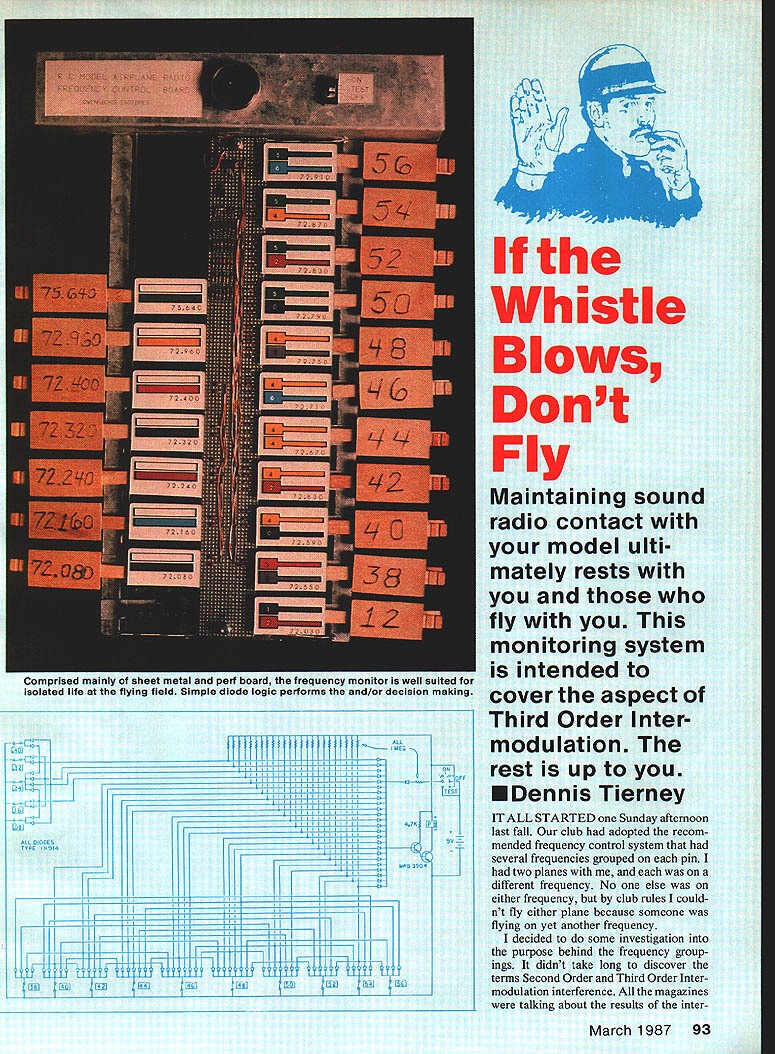
It all started one Sunday afternoon. Our club had adopted the recommended frequency control system with several frequencies grouped on each pin. I had two planes, each on a different frequency. No one else was on either frequency, but by club rules I couldn't fly because someone was flying on another frequency.
I investigated the purpose behind the frequency groupings and discovered Second‑Order and Third‑Order intermodulation interference. After testing (thanks, guys), it became clear that Third‑Order Intermodulation was the primary concern. A short program to calculate interfering frequencies (2 × f1 − f2) revealed a definite pattern: two frequencies of a particular separation can produce a third, offending frequency.
If a pin board could monitor frequencies in use and determine prohibited frequencies, more people could fly more of the time.
Intermodulation and the solution
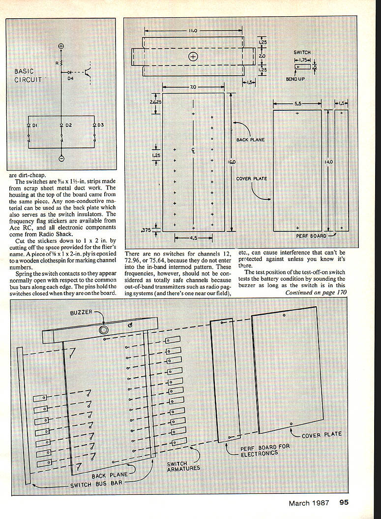
The solution is simple. A switch on each pin feeds an AND gate for each set of offending frequencies. Those AND gates feed an OR gate which sounds an alarm if any forbidden combination occurs. AND and OR gates are basic decision‑making parts of a computer: an AND gate produces an output only when all its inputs are active; an OR gate produces an output when any one of its inputs is active.
- Our AND gates have three inputs (output when input 1 AND input 2 AND input 3 are active).
- The OR gate has 18 inputs (output when input 1 OR input 2 OR … OR input 18 is active).
- The OR output drives an amplifier that activates a piezo buzzer.
Rather than using integrated‑circuit gate packages (which require power supplies and are more expensive), a diode arrangement was chosen. It is dirt‑cheap and requires only a 9‑V battery for power.
Construction
Materials and assembly details:
- Switch strips: 9/16 × 1 1/4‑in. strips made from scrap sheet‑metal ductwork; the housing top board came from the same piece.
- Back plate: any nonconductive material, which also serves as switch insulators.
- Switch contacts: spring the switch contacts so they appear normally open with respect to the common bus bars along each edge; pins hold switches closed when they are on the board.
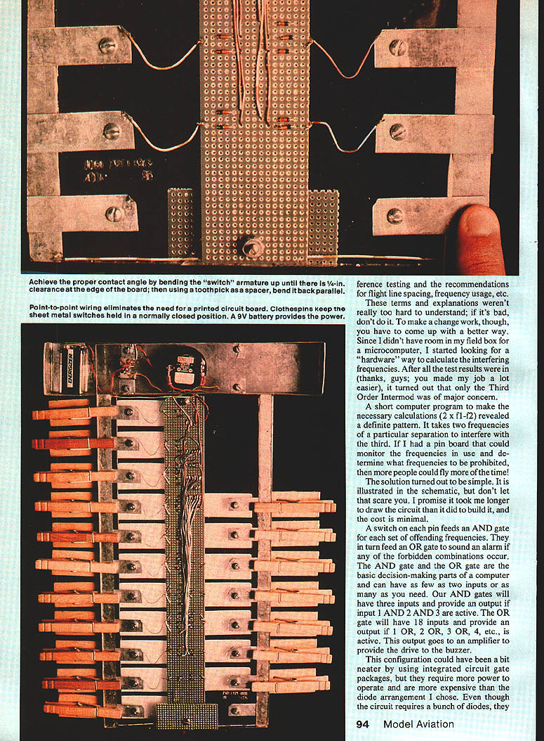
- Armature adjustment: achieve proper contact angle by bending the switch armature up until there is 1/16‑in. clearance at the edge of the board, using a toothpick spacer; then bend back parallel.
- Wiring: point‑to‑point wiring eliminates the need for a printed‑circuit board.
- Marking channels: frequency flag stickers are available from Ace RC or Radio Shack. Cut the stickers down to 1 × 2 in., removing the space provided for the flier's name. Epoxy a piece of 3/8 × 1 × 2‑in. ply to a wooden clothespin to mark channel numbers. Clothespins keep the sheet‑metal switches held in the normally closed position.
- Power and components: a 9‑V battery provides power; electronic components are standard Radio Shack parts.
This configuration requires a number of diodes but is inexpensive and quick to build. It likely took longer to draw the schematic than to assemble the board.
Operation and testing
- For normal operation move the test‑off‑on switch to the ON position.
- The TEST position checks battery and buzzer by sounding the buzzer while the switch is held in this position.
- To verify proper interlock operation: remove pins 44 and 46. Now removal of either pin 42 or 48 should sound the alarm. These are examples of the possible forbidden combinations; finding all combinations can be instructive and fun.
Notes and recommendations
- Proper flight‑line spacing and pilot judgment remain essential. Don’t fly your plane right in front of another transmitter 500 ft. away; that increases risk.
- There are no switches for channels 12, 72.96, or 75.64 because they do not enter the in‑band intermod pattern. However, they should not be considered totally safe—out‑of‑band transmitters (for example, nearby radio paging systems) can cause interference that this board cannot protect against unless you know it exists.
- Integrated‑circuit gate packages could make the configuration neater but require more power and are more expensive than the diode arrangement.
If the whistle blows, don't fly.
Parts List (Radio Shack Cat. No.)
- 1N914 diodes — 2 pk — 276-1620
- MPS3904 transistors — 2 — 276-2016
- P.B. piezo buzzer — 1 — 273-068
- Test‑off‑on switch — 1 — 275-664
- 1 Megohm resistors — 4 pk — 271-1356
- 4.7K ohm resistor — 1 — 271-1330
Transcribed from original scans by AI. Minor OCR errors may remain.

