
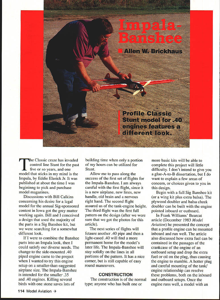
Impala-Banshee
Allen W. Brickhaus
The Classic craze has invaded control-line Stunt for the past five or so years, and one model that sticks in my mind is the Impala, by Eddie Elasick Jr. It was published about the time I was beginning to pick up and purchase model magazines.
Discussions with Bill Calkins concerning his desire for a legal model for the annual Sig-sponsored contest in Iowa got the grey matter working again. Bill and I conceived a design that used the majority of the parts in a Sig Banshee kit, but we were searching for a somewhat different look. If I were to combine the Banshee parts into an Impala look, then I could satisfy our diverse needs.
The change to the side‑mounted .40 piped engine came to the project when I wanted to try this engine setup on a smaller-than-suggested airplane size. The Impala-Banshee is intended for the smaller .35 and .40 engines. Killing several birds with one stone saves lots of building time when only a portion of my hours can be utilized for Stunt.
Allow me to pass along the success of the first set of flights for the Impala-Banshee. I am always careful with the first flight, since it is a new airplane: new lines, new handle, old brain and a nervous right hand. The second flight assured us of the tank‑engine height. The third flight was the first full pattern on the design (after we were sure that we got the photos for this article).
The next series of flights will feature another .40 pipe and then a light‑cased .40 will find a more permanent home for the model's later life. The Impala-Banshee stays solidly on the lines in all portions of the pattern. It has a nice corner, but is still capable of easy round maneuvers.
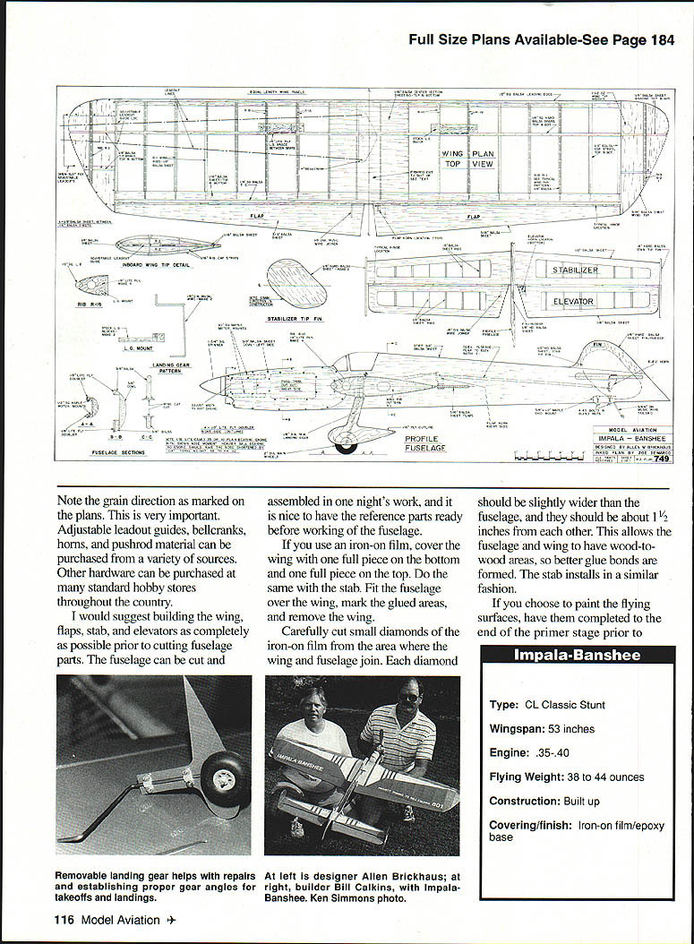
- Type: CL Classic Stunt
- Wingspan: 53 inches
- Engine: .35–.40
- Flying weight: 38 to 44 ounces
- Construction: Built up
- Covering/finish: Iron-on film / epoxy base
Construction
The construction is of the normal type; anyone who has built one or more basic kits will be able to complete this project with little difficulty. I don't intend to give you a glue‑A‑to‑B dissertation, but I do want to explain a few areas of concern and choices given to you in this design.
Begin with a full Sig Banshee kit (or a wing kit plus extra balsa). The plywood doubler and balsa cheek doubler can be built with the engine pointed inboard or outboard. In Frank Williams' Bearcat article (December 1983 Model Aviation) he presented the concept that a profile engine can be mounted inboard and run well. The article also discussed how extra fuel can be contained in the passages of the crankcase of the engine on an outboard setup and drop the extra fuel or oil on the plug, causing the engine to stumble. A hotter plug and careful mounting of the tank/engine relationship can resolve these problems, both on the inboard and outboard setups. Once the engine runs well, a model with an outboard setup will perform satisfactorily.
For the wood fuselage, use 6– to 7‑pound stock wood. Lighter wood will allow unwanted twisting of the fuselage during maneuvers. If you choose to use iron‑on film for flying surfaces, choose wood that will add strength where the parts are being built without adding excess weight. Painted-on coverings will add quite a lot of total weight; lighter wood can be selected when paint is not used. Spars need dense stock for stiffness; the stabilizer should be slightly dense as should the elevators. Note the grain direction as marked on the plans — this is very important.
I would suggest building the wing, flaps, stab, and elevators as completely as possible prior to cutting fuselage parts. The fuselage can be cut and assembled in one night's work, and it is nice to have the reference parts ready before working on the fuselage.
If you use iron‑on film, cover the wing with one full piece on the bottom and one full piece on the top. Do the same with the stab. Fit the fuselage over the wing, mark the glued areas, and remove the wing. Carefully cut small diamonds of the iron‑on film from the area where the wing and fuselage join. Each diamond should be slightly wider than the fuselage, and they should be about 1½ inches from each other. This allows the fuselage and wing to have wood‑to‑wood areas, so better glue bonds are formed. The stab installs in a similar fashion.
If you choose to paint the flying surfaces, have them completed to the end of the primer stage prior to attaching them to the fuselage. There is less to bang on the end of a table, hit the ceiling, or insert in a running ceiling fan while the model is in an early stage of construction.
On profile models, the horns can be fitted at the aft end of the wing or stab slot prior to fitting the wing or stab. This reduces unsightly or excess fuselage holes, which may have to be filled and finished later. Use of two nylon horns mated together (as Custom Models kits do) adds strength without excess weight.
Use plenty of straightedges, lines, and incidence meters to be sure all thrustlines are parallel to each other. No moving surface can be put in any kind of neutral position if the main parts of the structure are askew.
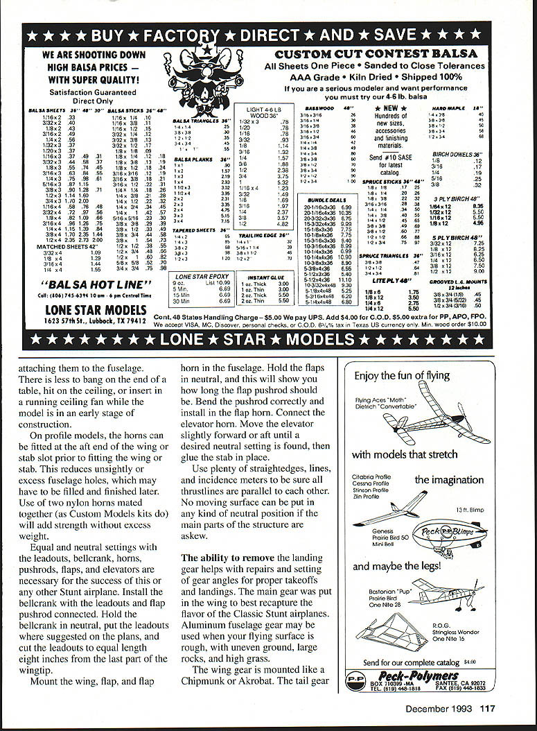
The ability to remove the landing gear helps with repairs and setting of gear angles for proper takeoffs and landings. The main gear was put in the wing to best recapture the flavor of the Classic Stunt airplanes. Aluminum fuselage gear may be used when your flying surface is rough, with uneven ground, large rocks, and high grass. The wing gear is mounted like a Chipmunk or Akrobat. The tail gear is attached with two 4‑40 bolts, with blind mounting nuts embedded in the motor mount.
The landing‑gear area is further braced with 1/8" lite ply sections. One piece fits behind the landing‑gear blocks and between the top and bottom spars; four others copy the airfoil shape and double the two ribs holding the landing gear blocks forward of the spars.
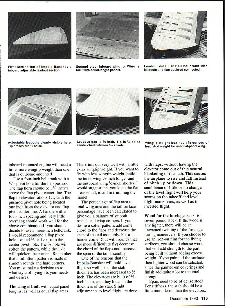
The inboard wingtip is not as complicated as the drawings suggest. The purpose is to create a hole or slot for the leadouts. The two 1/16" inboard wingtips are separated by a 1/8" piece near the leading edge, and another at the trailing edge. This allows a 1/8" gap for the leadouts. Once this is glued in place, treat it like the outboard wingtip construction: add the half ribs R‑2, capstrip them, and then glue in place the extra 1/8" balsa tip braces as shown. Approximately 1½ ounces of weight was installed at the location shown on the plans. If you decide to build an unequal‑panel wing, adjust the amount of tip weight accordingly.
Leadout detail
Install a bellcrank built for equal‑length panel leadouts. Hold the bellcrank in neutral, put the leadouts where suggested on the plans, and cut the leadouts to equal length — eight inches from the last part at the wingtip. Mount the bellcrank with the leadouts and flap pushrod connected.
Use a four‑inch bellcrank with a 13/64" pivot hole. The flap pushrod/flap horn should be 1‑1/8 inches above the flap pivot centerline. A flap‑to‑elevator ratio of 1:1 is recommended, with the pushrod pivot hole being located about 1/8 inch inboard of the elevator/flap pivot centerline. With the four‑inch spacing, very little overhang should work well.
If you decide to use a three‑inch bellcrank, locate the flap pivot hole about 5/16" from the center pivot hole. A 5/16" location will soften the pattern; a shorter distance will quicken corners. Remember: full Stunt patterns are made with smooth rounds, not hard corners. You must make the decision what style of flying fits your needs and desires.
Build the wing with equal panel lengths and equal flap areas; this trims out very well. If you want less wingtip weight, build the inner wing 1/8" longer and the outboard wing 1/2" shorter. I suggest you keep flap areas equal to aid in trimming the model.
The percentage of flap area to total wing area and the tail surface percentage have been calculated to give a balance of smooth rounds and crisp corners. If you desire a softer pattern, add some chord to the flaps or decrease the span of the tail assembly. For harder corners, which are more difficult to fly, decrease the chord of the flaps or increase the span of the tail assembly.
One of the reasons the Impala-Banshee holds level flight so well is that the stabilizer thickness has been increased (about 1/2"). The elevators are built of 1/4" balsa and fit into the thickness of the stab. Slight adjustments for level flight are done with the flaps; having the elevator come out neutral and blanketing the stab causes the airplane to rise or fall instead of pitch up or down. This small change, with little or no change in level flight, will help scores for takeoff, level flight, and maneuvers, as well as inverted flight.
Adjust inboard/outboard engine mounting as needed: an inboard‑mounted engine will need a little wingtip weight; an outboard‑mounted engine may require more.
Adjustable leadout guides, bellcranks, horns, and pushrod material can be purchased from a variety of sources. Other hardware is available at many standard hobby stores throughout the country.
Finish
The finish you desire is your choice. My Envoy article (June 1986 Model Aviation) outlines one method I have used. The premise is the same: Hobbypoxy II glue can still be used, as well as the Sig Epoxolite fillet material. Hobbypoxy Stuff, Super Poxy primer, or Dap spackling compound can be used for a surface primer over the glue base.
I have found that Formula U, Rust‑Oleum, and X‑O Rust from a spray can are compatible when given a little time to cure before adding the next color. The Rust‑Oleum silver is not fuelproof, and Rust‑Oleum does not make a clear. Formula U clear has been used for a final gloss coat over all of these products.
If you use iron‑on covering, design a paint scheme such that it's not necessary to tape over any paint that has film underneath. Try to have about 1/4" separation between colors.
Flying
The first flights were careful, and the model required little further trimming. Bill Calkins did a fine job of carrying out the design ideas brought forth in our pre‑project discussions. As a result, the Impala‑Banshee will give you a fine‑flying profile Stunt model that will do well for you on the contest circuit — or perhaps you'll simply enjoy flying it. Either way, it is sure to bring back thoughts of the Golden Age of Stunt.
Materials
- ABC Hobby Supplies
P.O. Box 2391 Clarksville, IN 47131
- Aero Products
1880 Scenic Hwy Snellville, GA 30278
- C.F. Slattery
2101 Logan Ave New Albany, IN 47150
- Carolina‑Taffinder
8345 Delhi Road North Charleston, SC 29418
- Custom Models
5515 Bridgeton Dr Arlington, TX 76018
- Pro‑Stunt Products
9 Union Ave Little Ferry, NJ 07643
- Sig Manufacturing
401‑7 South Front St. Montezuma, IA 50171
- S.S.T. Products
28746 Westfield Livonia, MI 48150
If you have any questions, please contact me at P.O. Box 206, Golconda, IL 62938.
Transcribed from original scans by AI. Minor OCR errors may remain.

