
Indicator
Jim Haught
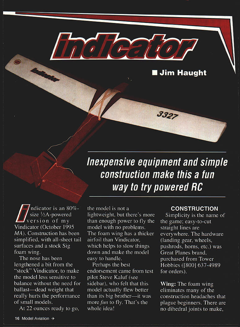
Indicator is an 80%-size, 1/2A-powered version of my Vindicator (October 1995 MA). Construction has been simplified, with all-sheet tail surfaces and a stock Sig foam wing.
The nose has been lengthened slightly from the "stock" Vindicator to make the model less sensitive to balance without the need for ballast—dead weight that really hurts the performance of small models. At 22 ounces ready to go, the model is not a lightweight, but there's more than enough power to fly the model with no problems.
The foam wing has a thicker airfoil than the Vindicator, which helps to slow the model and make it easy to handle. Perhaps the best endorsement came from test pilot Steve Kaluf (see Test Pilot's Report), who felt this model actually flew better than its big brother—it was more fun to fly. That's the whole idea!
Construction
Simplicity is the name of the game; easy-to-cut straight lines are everywhere. The hardware (landing gear, wheels, pushrods, horns, etc.) was Great Planes brand, purchased from Tower Hobbies (800-637-4989).
Wing
The foam wing eliminates many of the construction headaches that plague beginners. There are no dihedral joints to make, no leading edges to carve, or framework to be covered.
Order the wing from Sig Manufacturing (Montezuma, IA; part number RP-FC-500). It's sold as a replacement part for a series of kit models.
All you really need to do to the wing is sand it lightly with fine-grit paper to remove any bumps or "fuzzies" from manufacture. Then it will need some kind of fuel-proofing protection. This isn't easy because the solvents in many paints will attack (melt) foam.
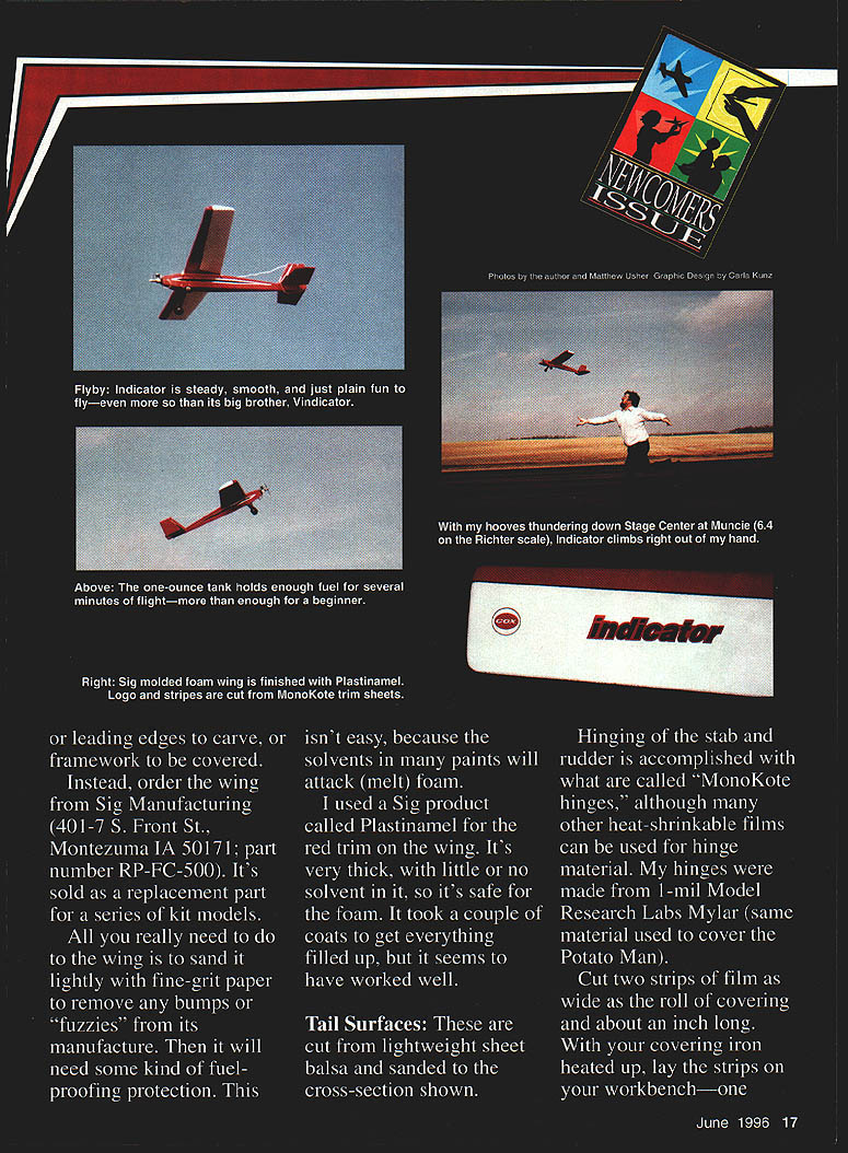
I used a Sig product called Plastinamel for the red trim on the wing. It's very thick, with little or no solvent in it, so it's safe for foam. It took a couple of coats to get everything filled, but it has worked well.
Tail Surfaces
The tail surfaces are cut from lightweight sheet balsa and sanded to the cross-sections shown.
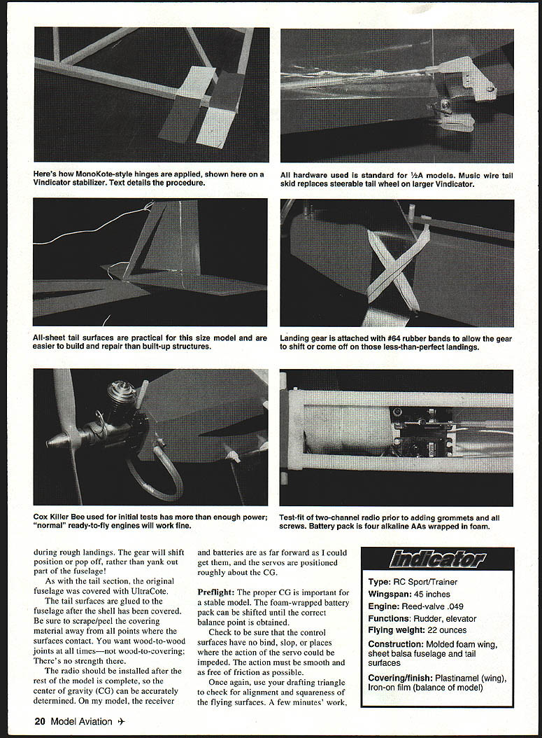
Hinging of the stabilizer and rudder is accomplished with Monokote-type hinges (heat-shrinkable film). I made hinges from 1-mil Model Research Labs Mylar. Cut two strips of film as wide as the roll and about an inch long. With your covering iron heated, lay one strip adhesive-side up and the other adhesive-side down. Slide the strips together with about 1/8–3/16" overlap at the edge. Touch the tip of the iron to the overlap to activate the adhesive and join the rectangles in a spot weld. Be sure the entire width of the overlap is joined—this is equivalent to a pin in a normal hinge.
Cut the long strip to the width of individual hinges—perhaps 1/8". Make enough hinges to cover the full hinge area. Attach the hinges to one surface first, alternating between top and bottom. Align the hinges so the overlap is centered on the hinge gap. With the full line of hinges in place, mate the second surface to the hinges. Light tension can be applied to give a snug, gapless fit. Proceed along the hinge line until the full length is joined.
Cover the stabilizer and rudder with heat-shrink film (I used Carl Goldberg Models UltraCote).
Alignment of the tail surfaces is easier if the stabilizer and rudder are joined before attaching the assembly to the fuselage. Carefully mark the fuselage centerline. Trim the covering away where the rudder will make contact—you want wood-to-wood joints. Use thick CyA to join the parts, making sure the rudder is positioned on the centerline and doesn't lean to one side. Use a drafting triangle to hold alignment until the glue sets. The assembly may be set aside until the fuselage is completed.
Fuselage
The fuselage is a sheet-balsa box built bottom-up. Attach the sides to the bottom first; add internal items—rails, braces, tank, etc.—then attach the top sections. Sand the fuselage shell to shape. Use a drafting triangle repeatedly during construction to ensure the fuselage is square.
The landing gear is mounted to the bottom of the fuselage. Crisscrossed #64 rubber bands allow some give during rough landings; the gear will shift position or pop off rather than yank out part of the fuselage.
If the fuselage shell is covered with UltraCote, glue the tail surfaces to the fuselage after the shell has been covered. Be sure to scrape or peel the covering away at the points where the surfaces contact—you want wood-to-wood joints, not wood-to-covering.
There is no sense installing the radio until after the rest of the model is complete. The center of gravity (CG) can then be accurately determined. Receiver batteries may need to be placed far forward; you can position servos roughly about the CG if necessary.
Preflight
Proper CG is important for a stable model. A foam-wrapped battery pack can be shifted until the correct balance point is obtained.
Check to be sure the control surfaces have no bind or slop where the action of a servo could be impeded; motion must be smooth and free of friction. Use a drafting triangle to check alignment and squareness of the flying surfaces—a few minutes' work.
Test Pilot's Report
Steve Kaluf
It is always fun to be involved with a new design; I take particular pleasure when I'm allowed to be the test pilot. Indicator's wing is a bit flatter than the Vindicator's, so I hoped it would fly a bit more slowly.
Jim picked a calm, warm day for Indicator's first flight—fortunate considering his usual luck for windy, cold days. The Cox .049 started right up. I had never used the Cox Cobra radio before, but I liked the one-hand grip and stick configuration; it would make a nice system for an RC hand-launch glider that did not require mixing.
We determined a hand launch was best since there was no throttle to work with. A hand launch ensures a good, straight start. If you try Rise-Off-Ground (ROG), engine torque can make the model turn in a circle before you can correct with the rudder. Indicator, however, would likely be better at ROG than most 1/2As because of its long tail moment.
Hand-launch technique:
- Face directly into the wind and keep the wings level, with the nose pointed at the horizon or slightly down.
- Jog along with the model for a few steps and give it a firm push (not a throw).
- If the launcher tosses the aircraft too hard, the engine may starve for fuel and die; too soft and the airplane won't reach flying speed.
- Be ready on the controls to correct for any errors by the launcher.
Indicator flew right out of Jim's hands and required very few corrections. The engine was slightly rich—a good setting since it tends to lean out a bit in flight. There is plenty of power available; you'll probably be amazed at how well an .049 hauls this bird around.
Flight characteristics:
- Turns are even left and right and feel "groovy." A bit of elevator is needed to maintain level flight in a turn.
- Indicator recovers from turns nicely with little slip on exit.
- Stalls are very gentle with no tendency for a wing to drop (no tip stall).
- After about five minutes on the one-ounce fuel tank the engine cut off with the model fairly high; there was very little trim change at cutoff—only a slight nose-down attitude, which is good for a trainer.
Subsequent tests were flown in winds up to 15 mph. Indicator handles this amount of wind much better than most 1/2As. Indicator is far from an aerobatic airplane, but it can perform simple maneuvers like loops and stall turns. It's designed as a cruiser—to give you time to get used to the controls without great risk to the model.
I would recommend this model to anyone as a first building/flying experience. It has been a fun project, and I look forward to having a lot of fun with Indicator—and I hope it will do the same for you.
Steve Kaluf
Notes and Tips
- During rough landings, the gear will shift position or pop off rather than yank out part of the fuselage.
- When covering the fuselage shell with UltraCote, glue the tail surfaces after covering and scrape/peel covering away where the surfaces contact for wood-to-wood joints.
- Install the radio and position batteries/servos after the model is mostly complete so the CG can be set accurately.
- Check for smooth, free motion of control surfaces and use a drafting triangle to confirm alignment and squareness.
Specifications
- Type: RC Sport/Trainer
- Wingspan: 45 inches
- Engine: Reed-valve .049 (Cox Killer Bee used in initial tests)
- Functions: Rudder, elevator
- Flying weight: 22 ounces
- Construction: Molded foam wing, sheet balsa fuselage and tail surfaces
- Covering/finish: Plastinamel (wing), iron-on film (remainder)
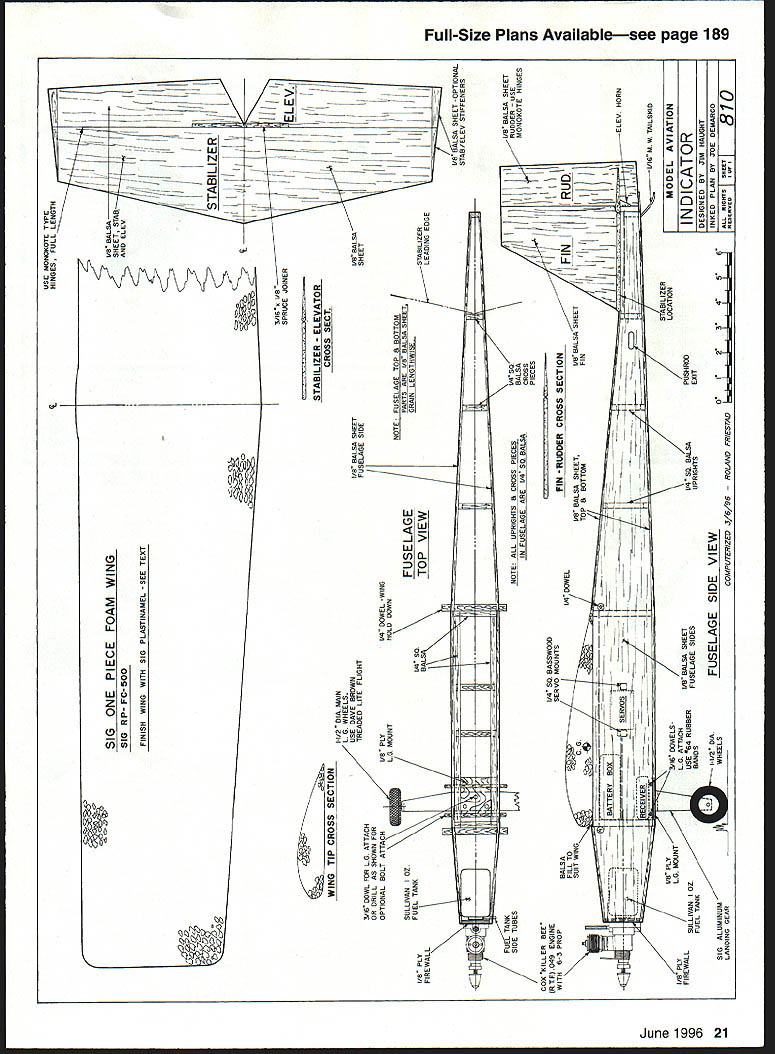
Plans and Materials Notes
- Full-size plans available — see page 189 (original publication reference).
- Sig one-piece foam wing: SIG RP-FC-500. Finish wing with SIG Plastinamel (see text).
- Use Monokote-type hinges as shown.
- Stabilizer and elevator, fin and rudder cross-sections, fuselage top and side views, and wing tip cross-sections are shown in the plans.
- Landing gear attached with #64 rubber bands to allow some give; in rough landings the gear will shift or pop off rather than damage the fuselage.
- Test-fit a two-channel radio prior to adding grommets and screws.
- Battery pack: four alkaline AAs wrapped in foam.
- Cox Killer Bee (or similar .049 engines) provides enough power; normal ready-to-fly engines will work fine.
- A music-wire tail skid replaces the steerable tail wheel used on the larger Vindicator.
Transcribed from original scans by AI. Minor OCR errors may remain.

