
INVADER MK.IV
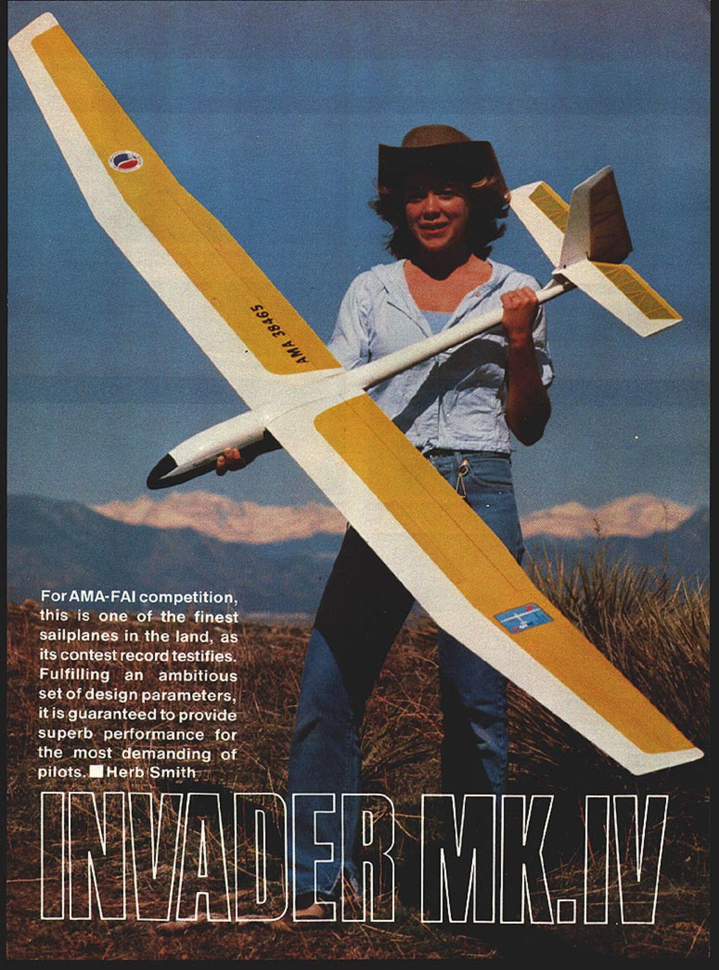
For AMA-FAI competition, this is one of the finest sailplanes in the land, as its contest record testifies. Fulfilling an ambitious set of design parameters, it is guaranteed to provide superb performance for the most demanding of pilots. — Herb Smith
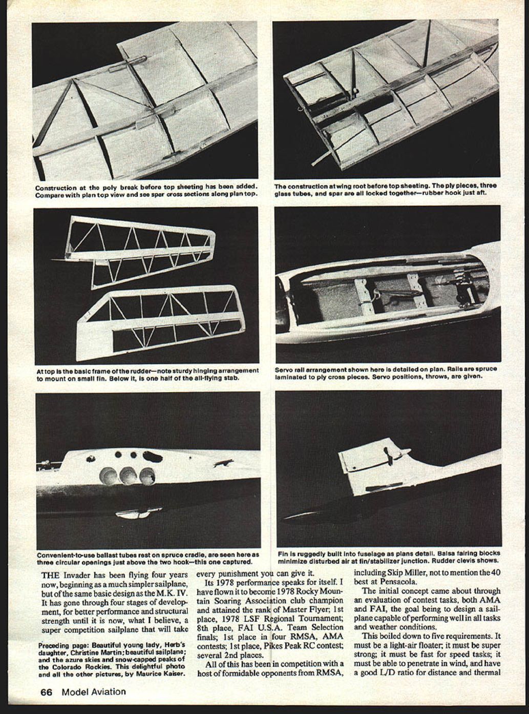
The Invader has been flying four years now, beginning as a much simpler sailplane but of the same basic design as the M.K. IV. It has gone through four stages of development for better performance and structural strength until it is now, what I believe, a super competition sailplane that will take every punishment you can give it.
Its 1978 performance speaks for itself. I have flown it to become 1978 Rocky Mountain Soaring Association club champion and attained the rank of Master Flyer; 1st place, 1978 LSF Regional Tournament; 8th place, FAI U.S.A. Team Selection finals; 1st place in four RMSA AMA contests; 1st place, Pikes Peak RC contest; and several 2nd places.
All of this has been in competition with a host of formidable opponents from RMSA, including Skip Miller, not to mention the 40 best at Pensacola.
The initial concept came about through evaluation of contest tasks, both AMA and FAI, the goal being to design a sailplane capable of performing well in all tasks and weather conditions.
This boiled down to five requirements:
- It must be a light-air floater.
- It must be super strong.
- It must be fast for speed tasks.
- It must be able to penetrate in wind.
- It must have a good L/D ratio for distance and thermal work.
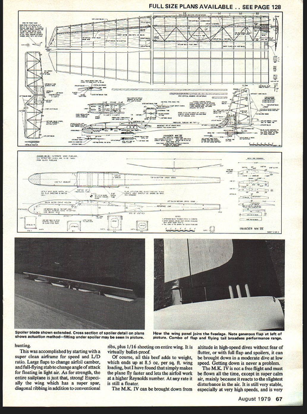
This was accomplished by starting with a super-clean airframe for speed and L/D ratio. Large flaps change airfoil camber, and a full-flying stab changes angle of attack for floating in light air. As for strength, the entire sailplane is just that—strong! Especially the wing, which has a super spar, diagonal ribbing in addition to conventional ribs, plus 1/16 in. sheeting on the entire wing. It is virtually bullet-proof.
Of course, all this beef adds to weight, which ends up at about 8.5 oz. per sq. ft. wing loading, but I have found that simply makes the plane fly faster and lets the airfoil work at a higher Reynolds number. At any rate it is still a floater. The M.K. IV can be brought down from altitude in high-speed dives without fear of flutter, or with full flap and spoilers it can be brought down in a moderate dive at low speed. Getting down is never a problem.
The M.K. IV is not a free-flight ship and must be flown actively all the time, except in super calm air, mainly because it reacts to the slightest disturbance. It is still very stable, especially at very high speeds, and is very responsive to control commands.
Flown with a gentle touch, it is a very docile sailplane, easily flown by the intermediate pilot. In all, it is a super competition sailplane and a blast to fun-fly. Try a snap roll out of the bottom of a loop, or just give it full up stick, snap the rudder and hold it and let it do what it does. More fun than a barrel of monkeys.
Instructions
Fin and Rudder — Assemble fin spars and hinge assembly
- Rudder spars — 1/8 x 1/4 x 2 in. spruce, 2 pieces. Notch at hinge tab locations so that the spars contact each other with hinge tabs sandwiched between.
- Fin spars — 1/8 x 1/4 x 2 in. spruce, 2 pieces. Same as step one.
- Dry-run-assemble fin spar and rudder spar with hinges and 3/32 in. piano wire hinge pin in place. Clamp together. Check hinge positions and free movement. When satisfied, epoxy (5-minute or slow-dry) the spars and hinge units being careful not to get epoxy in hinge bearings. Note: Some hinge holes are tighter than others and may necessitate making the pin smaller. To do this, chuck the pin in a drill and polish down using 400 or 320 wet-or-dry paper. Carve clearance opposite hinge bosses on fin and rudder spars.
- Assemble fin first. Put wax paper on plan.
- (A) Assemble inner frame first. This consists of the fin/spar hinge assembly, bottom 1/8 x 3/4 in. spruce piece (with 3/32 in. hole drilled in position shown for control cable housing — be as accurate as possible), and three pieces of 1/4 x 1/4 in. balsa. Epoxy unit together and wipe excess off top of sticks.
- (B) Remove from plan when dry; add 1/4 in. thick balsa fillet to front of fin. Do not airfoil at this time.
- (C) Trim top hinge tab to clear stab hinge tube by trying 1/32 in. plywood side with 1/8 in. brass tube through hole. Trim or sand top edges of 1/32 in. plywood sides so they align with top of stab boss by comparing to plan. Do this with brass tube through hole in both side pieces for alignment. This is the neutral position for the stab.
- (D) Rough outer stab cable housing at epoxy areas and epoxy to 1/8 x 1/4 in. spruce and 1/4 x 1/4 in. balsa with top of housing at exact height and contour shown. Shim top out from balsa stick if needed.
- (E) Plywood sides — dry-assemble two sides with 1/8 x 3/16 in. long brass tube in place through holes and resting back against fin. Insert 3/32 in. piano wire stab rod through using a small square, slide plywood both ways. Use a small square to hold sides in place. When sure they align, remove and rough up glue areas. Spread epoxy thinly on mating surfaces as above procedure, making sure it is centered (extends 9/32 in. each way) and square two ways.
- (F) From 1/4 x 1/4 in. balsa, make two stab bosses with 1/8 in. drilled hole for stab hinge tube. Be sure hole is centered 5/16 in. from sides of boss. Glue both parts in place being careful to make top parallel with plywood.
- (G) Sheet fin above stab with 1/16 in. balsa. Cut radius slot for front stab rod and brass tube at 1-3/4 in. radius from rear hinge hole. Allow a full 3/8 in. travel each way. After stab is assembled, check that it moves freely and, if necessary, widen radius slot.
- (H) Airfoil the leading edge. Do not fix to fuselage at this time (will be covered in fuselage instructions).
Rudder
- Cover plan with wax paper.
- Make shims as shown at right of rudder plan.
- Pin rudder spar and hinge assembly in place flat on plan. This establishes a centerline 1/16 in. above plan.
- Pin down T.E. shims where shown, being sure 1/32 in. pad is 1/16 in. inside rear of plan as shown.
- Cut T.E. stock and top piece, pin and glue in place. Trim top piece only after rudder is removed from plan.
- Cut remaining perimeter sticks and pin in place using proper shims and glue. Note: the 1/8 x 3/16 in. stick just above fin should be fit around hinge boss and is epoxied along with gusset.
- Cut, fit and glue diagonal rib sticks, being sure to use shims under each end.
- Remove from plan and cut two pieces of 1/8 x 3/8 in. spruce for control horn boss. Notch inside slightly so that two pieces will sandwich over hinge tab, and epoxy in place.
- Place control horn in position with boss 1/16 in. from bottom of rudder and a slight down angle to line up with control rod hole. Control hole should be on centerline of hinge pin as shown in top view. Horn may be offset to left or right side depending on servo travel.
- Trim top of rudder and cut to line. Sand leading edge to shape. After final sanding, glue fillets at top and glue.
- Fill sides of stab and rudder fin so they may be sanded to match centerline. Sand leading edge stick to 1/16 in. radius. Install hinges of rudder. Sand and fit to fuselage.
Stabilizer
Cover plan with wax paper.
- Cut leading-edge (L.E.) stock (4 pcs.) to fit. Pin down T.E. shims of 1/32 in. base type in positions shown. Pin and glue T.E. in place.
- Cut, pin and glue L.E. and tip pieces in place. Use 1/32 in. shims under L.E.
- Cut two pieces of 1/8 x 3/16 in. balsa about 3 in. long. Stack together and mark hole locations, keeping holes away from ends. The 1-1/4 in. center-to-center dimensions should be as accurate as possible. Holes should be centered in stick and be drilled square through sticks. Mark top of sticks so as to keep from inverting in assembly. While still pinned together, trim ends to position holes the correct distance from the end. Do not glue in place at this time.
- Squeeze 3/16 in. brass tubes about 3/4 in. from end with pliers—very slightly. File or sand radius on ends of stab rods and push through tube until they will push through snugly. Remember, there will be two rods in place at assembly, therefore twice the holding power to keep stab on rods.
- Insert brass tubes in drilled sticks with squeezed ends outboard and check for alignment. Be sure ends of tubes are flush with sticks, pin and glue assembly in place. If holes are well centered in sticks, place 1/32 in. shim under outboard ends of tubes. Be sure tubes are square with plan and parallel.
- Cut two 1/8 x 3/16 in. balsa sticks to butt outboard ends of tubes and glue in place.
- Cut and glue the 1/16 x 3/16 in. cross and diagonal sticks in place flat on plan. Install gussets at tip corners.
- Remove from plan. Cut from 1/16 in. hard balsa four top and bottom spars to match plan. Mark locations on stabs and glue in place. Sheet top and bottom of inboard section as shown.
- Clip pieces as shown at right of stab and sand to shape.
- If desired, cross sticks may be filled with 1/16 in. sq. balsa and sanded to a symmetrical airfoil.
- Radius L.E. and finish-sand for covering.
Fuselage
- Drill and file an elongated slot on left rear side of wing boss to permit entry of 1/8 x 1/4 in. spruce cross brace. Insert spruce through slot until it butts opposite side and mark stick. Remove it and cut a notch 3/16 in. deep about 1/32 in. inside mark, and re-insert stick to check length. Trim and fit until it will bear against both sides. Epoxy in place and, after set, cut off flush with wing boss.
- Rough 3/32 x 2-9/16 in. brass tube with corner of file and epoxy into rear wing rod hole. Install two fiberglass tubes and epoxy from inside.
- Cut and fit 1/4 x 1/4 in. spruce cross brace at front of wing boss. Keep it high in location as shown to clear spoiler pull. Epoxy in place.
Flap actuator assembly — Use acid-core solder
- Bolt control horn onto 3/32 x 2-5/8 in. minimum brass tube at centerline, or to suit servo installation. It may be necessary to file small notches in tube at bolt locations to allow the horn to be square. Bend a piece of soft 1/16 in. wire as shown and solder in place to reinforce brass tube and anchor horn.
- Snap control horn and brass tube assembly into fuselage. Bevel ends of brass tube to ease installation into fuselage. Use the 1/16 in. steel guide through fuselage hole, insert rod as a handle, and slip steel rod into tube and guide it into hole in one side of fuselage. Use a little pressure and wiggle. If tube is too long, it may be filed shorter; it must extend about 1/32 in. out each side of fuselage. This is a ticklish job but will go with patience. It may be necessary to file more bevel on the end of brass tube. Once the tube has entered one side, slide the steel rod through both sides of fuselage and slide the brass tube through the other side.
- Bend 1/16 in. piano wire (2 pcs.) 90° and 7/8 in. long as shown in detail. Clean inside of brass tube with acetone or alcohol by pushing a small saturated piece of tissue paper through hole. Use a soldering gun and acid-core solder on this unit. Cut small pieces of solder and insert into the end of tube trying to get some acid in with it. Hold soldering gun to end of tube and melt solder to tin inside of tube. Do the same to other end. Rough ends of 1/16 in. wire where they fit into brass tubes and tin with solder.
- Clamp or tape control rod to hold control horn in position (slightly aft of straight down). At this point you need a helper with a pair of pliers. Center brass tube in fuselage to extend equally each side of fuselage. Have helper hold fuselage steady and hold end of brass tube from sliding. Slip brass washer on opposite end and hold bent wire with pliers at end of wire. Heat tinned end while holding it against end of brass tube till solder melts and wire begins to slide in. Apply more solder and push wire into the 1/4 in. position and parallel with bottom of wing boss. Hold heat till sure solder has flowed inside tube. Continue holding wire till solder changes color indicating it is solid.
- Release control rod from capture. On the side just soldered, slip a piece of cardboard or a piece of paper folded to 5 or 6 thicknesses (about 1/64 in.) between washer and fuselage, and tape in place to provide end play through fuselage. Cut 3/16 x 3/8 in. spruce side rails to length shown on plan and use as alignment tools to solder other flap wire in place. Slide one 1/4 in. wing rod through rear wing rod tube. On soldered side, place one spruce stick on top of flap wire and extend under wing rod and hold in place with two clothes pins or small clamps. Clamp very lightly so as not to crush spruce, causing misalignment. Again capture control rod as before and have helper hold fuselage and flap wire just soldered so it will not be pushed through. Clamp other wire on spruce stick, slip on brass washer, and hold wire against tube while holding spruce up under wing rod matching other side. Apply soldering gun and repeat procedure used on other side.
Flap safety guides
(For those of us who dork landings.) These guides slide into the hole in end of flap to guide wire into slot in the event wings sweep forward then return to fuselage. Round ends of piano wire with a file. Bend brass strip to fit over brass tube to help center wire. Use a round file to open tube to fit guide and to hold while soldering in place. Keep guides as compact as possible.
- Check fit. Guides should be sloppy loose.
Assemble fin to fuselage
- Drill hole in top of fuselage for control cable. Hole may be up to 1/4 in. diameter.
- Try fin for fit. Spar should butt end of fuselage and bottom hinge tab slide inside.
- Insert long wing rod in wing rod tube and tape it centered.
- Slip stab rod in stab hinge hole and sight to wing rod for level. Use a straightedge down side of fin for center, compare to seam in fuselage.
- Remove and flat-file top of fuselage where fin contacts it. Coat contact area with 5-minute epoxy and repeat step 4. Hold by hand and keep checking alignment till epoxy sets.
- Fillet fin to fuselage with more epoxy.
- Epoxy stab control inside fuselage as shown through rear of fuselage.
Tail cone and skid
- Cut notch in balsa block 9/16 in. deep to fit over fin spar and hinge. Slip block in place and press hard against end of fuselage. Pencil-mark diameter of fuselage end on block. Remove and make a circular cut 1/32 in. deep and 1/8 in. from front of block. Carve a step on the end of block to slip inside of fuselage by cutting approximately 1/32 in. inside of fuselage mark on end of block. Re-coat fin spar with epoxy and coat contact areas of block and install.
- Carve block to shape and sand.
- Cut skid to shape and radius notch to fit clear of rudder pin. Skid will be off center. File a groove around end of rudder pin to help in removal. Epoxy skid in place. A safety pin should be used to keep rudder pin from coming out.
Rudder control cable
- Cable may be exited on left or right side, depending on servo travel. Drill 5/32 in. hole at centerline of exit shown on plan approximately 1/4 of centerline of fuselage and 1/8 in. below top of fuselage and 2-1/8 in. from end of fuselage.
- With a small round file, angle exit hole till cable housing will exit in a straight line towards rudder horn.
- Epoxy in place with end of housing 2 in. from end of fuselage and other end running under flap actuator tube and over ballast tubes. Stab actuator cable follows same route.
Tow hook
- Position shown on plan is for optimum performance—see flight instructions.
- Fabricated hook shown is sufficient, but for serious competition a capture tow hook is advised and should be actuated by spoiler servo.
Ballast tubes (optional)
- Should be 5/32 in. O.D. thin-wall aluminum tubing (hardware store).
- Cut three holes at locations shown as high as possible to clear bottom of wing, left side only. Cut spruce cradle to match holes, to be epoxied to right inner side of fuselage to align and support tubes.
- Using one of the tubes as a mold, after removing all inside burrs, clamp tube and fill with lead. Lead will shrink enough to allow it to be pushed out with a wooden dowel. Place slugs with 1/32 in. clearance.
- Slide tubes in fuselage and epoxy heavily after roughing O.D. with corner of file at glue areas.
- File end of tubes flush with side of fuselage, and secure ballast with a strip of plastic tape.
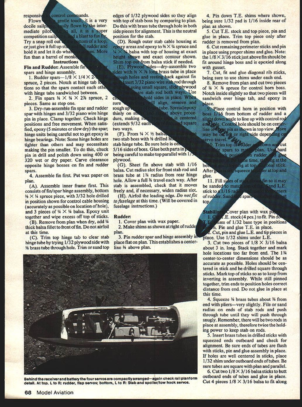
Radio installation
- Installation shown for Kraft radio. If other radio is used, it is essential that the same structural configuration be used for side rails and cross rails. Positions may be altered to suit radio.
- Shape side rails to fit contour of fuselage. Use Hobbypoxy #2 for all gluing in this area. Epoxy side rails in place. Fabricate, lay out and drill cross rails and braces, and epoxy into place.
- Loose-install servos, align and anchor front end of cables and all control linkages. Remove servos.
- Sand center seams of fuselage smooth and wet-or-dry sand entire fuselage to remove orange-peel effect in gel coat. Finish-paint fuselage and sand canopy bottom where needed to obtain good fit, and cut out rear of canopy to clear any control mechanism. Install hook in canopy and hooks on servo rails. Finish paint canopy.
- Install one Antiross skid or other suitable skid. Install radio and hook up all linkages. Assemble finished tail surfaces.
- Slide a glass wing rod in tube at marked C.G. and suspend fuselage on wing rod resting on two blocks of equal height on table. Lay 1 quarter, 1 nickel, and 1 penny on stab spar. Add ballast to nose or tail if necessary to bring fuselage level. Fill nose of fuselage with foam blocks to anchor ballast.
Wing
- Build right wing first. Cover plan with wax paper.
- Cut and fit bottom 1/16 in. sheeting to fit inboard plan exactly at butt, polyhedral joint and flap joint. Leave leading edge a little short so the line is visible. Pin down leading edge making sure stick is exactly 3/16 in. (Some sticks are wider one way than the other.) Use a straightedge to make sure stick is pinned down straight.
- Pin down 3/16 x 1/4 in. sub spar, using straightedge as in step 2.
- Ribs 1 through 13 are too long. Cut off back ends only to establish correct length at assembly. Drill ribs No. 1 through No. 8 for spoiler tube.
- Glue ribs No. 1 and No. 12 in place.
- Cut top and bottom 1/8 x 3/4 in. spar to length and cut angle at polyhedral end 1/8 x 1/4 in. as shown on both spars.
- Install bottom spar and Hot Stuff at each end to keep in place.
- Ribs No. 2 through No. 11 are cut in two, but not all the same, as spar cross sections differ at each rib out to No. 6 rib. Rib No. 2 has entire 3/8 in. spar section removed. Ribs No. 3, 4, 5 and 6 have 1/4 in. removed from back of spar notch to leave a 1/8 in. tab on front section. All remaining ribs, No. 7 through No. 11, have 1/8 in. removed from center of spar notches. Cut all ribs, keeping halves matched and install leading edge or D-section of ribs, and use ribs to position spar to rib notch. Hot-Stuff spar to bottom sheeting.
- Cut spar vertical members to match detail for both wings. Dry-install on top of bottom spar and check that wing rod tubes will fit. It is necessary to roll a piece of sandpaper and line-sand holes for tubes. Tubes should slide in holes freely. It may be necessary to trim front and back of vertical spar members to slip between tubes. Pin down through sheeting to be sure wing is flat on table.
- Trim rear sections of ribs No. 2 and No. 3 to fit and Hot-Stuff in place. Remove vertical spar sections and prepare enough Hobbypoxy #2 to epoxy spars and wing rod tubes. Assemble vertical spar members and tubes, including rear brass tube.
- Trim and install rear sections of ribs No. 4 through No. 12.
- Install rubber hook and 1/16 x 5/8 x 1-15/16 in. plywood reinforcements.
- Install top spar with #2 epoxy and re-coat wing rod tubes heavily, along with ribs No. 1 and No. 2 at all joints. Plug tube ends.
- Install L.E. backup pieces.
- Drill diagonal ribs for spoiler tube and install.
- Layout and cut notch in ribs No. 7, No. 8, No. 9, No. 10 and No. 11 for 3/16 x 3/16 in. balsa stick and install stick flush with top of rib.
- Install spoiler tube and attach to bottom of 3/16 in. stick with a notched block of 3/16 in. balsa.
- Box in spoiler bay with 1/16 in. balsa sheet to keep dirt out of wing.
- Reinforce glue joints where needed with Titebond or epoxy.
- Do not sheet top at this time.
Flap
- Cut two pieces 1/32 in. sheet balsa 2 in. wide and 3/32 in. shorter than inner wing panel for both bottom sections of flaps. Cut two pieces 1/32 in. sheet balsa x 2-1/32 in. for top sheeting.
- Notch corner of bottom sheeting 1 in. wide x 15/16 in. long to fit plywood inserts for flap actuator slot.
- Pin down bottom sheet.
- Cut plywood inserts as shown in detail, epoxy and stack. After set, check slot will slip easily on 1/16 in. rod. Run drill through safety guide hole and make loose slip fit on guide pin. Hot-Stuff assembly in place.
- Sand angle on top of flap spar to match angle on rib.
- Pin down flap spar, being sure it is parallel to wing sub spar and Hot-Stuff to bottom sheeting.
- Cut 24 ribs per detail by cutting a strip of 1/16 in. sheet balsa .30 in. wide. Cut off pieces 1-1/4 in. long and with straightedge, cut diagonally.
- Install ribs.
- Install top sheeting.
Outboard wing
- Cover plan with wax paper.
- Butt inboard wing section with outboard section plan, with inboard section propped up near rib No. 4, as indicated on plan, with a 2-1/2 in. block. Align perfectly and pin down. Joint will be built in.
- Cut and pin down 1/16 in. bottom sheeting from rib No. 13 to rib No. 21 to fit plan, leaving leading edge line barely exposed.
- Cut and pin down leading edge at each end and use a straightedge to pin down in between.
- Cut 1/16 in. x 1/4 in. spruce bottom spar to length and lay in place—do not glue.
- Cut rib spar notch out of ribs No. 12 and No. 13 to allow for spar splice. Do not install now.
- Glue in ribs No. 14 through No. 21, allowing ribs to position spar.
- Make four spar splices by trimming to 5-1/2° dihedral.
- Fit top spar and epoxy splices into place.
- Add short sub spar and rib No. 13 reinforcement, and epoxy along with rib No. 13.
- Cut and add 1/16 in. balsa shear web to both sides of spar as shown, using scrap ends of sheeting.
- Unpin trailing edge from rib No. 19 to No. 21 and cut washout shims from 3/16 in. balsa. Slide rear shim under trailing edge and wax paper. Slide end shim under wax paper and position under rib No. 21.
- Sheet top of panel and washout is built in.
- Wing tip is added after leading edge is shaped, and wing panel sanded.
- Build left wing to this point of completion before sheeting inboard section, using left wing for reference.
Finishing inboard section
- Again check for good fill of epoxy around wing rod tubes and reinforcements. Add more epoxy if needed.
- Sheet top and carefully trim spoiler bay.
- Cut spoiler blade to fit opening.
- Cut and sand ribs in spoiler bay to become floor for blade, leaving blade above surface slightly to allow sanding to wing contour. Then sand ribs more to let spoiler barely below surface of wing.
Finishing wing
- Plane or sand bottom of leading edge sheeting as shown on end view of wing full span.
- Radius leading edge—make a gauge to keep radius uniform.
- Sand trailing edge on top to continue rib contour until trailing edge is 1/16 in. thick.
- Wing tip instructions are on plan.
- Finish sand and MonoKote wing.
- Install spoiler pull-string and blades.
- Butt flap against wing and align ends to have clearance at both ends. Temporarily tape on bottom with Scotch tape or masking tape. Fold flap down against underside of wing and lay Mylar 1/2 in.-wide tape over wing, sub spar, and flap spar. Raise flap to neutral position and tape along bottom joint, removing temporary tape as you go.
Flying
- Be sure C.G. is correct.
- Check for warps in wing.
- Check that all controls work freely and return to neutral.
- Set stab and rudder neutral.
- Make first hand-glide from running attitude to feel lift and judge speed. Throw it straight and level fairly hard and get on controls quickly to get it straight and level fast. I can almost guarantee it is trimmed perfectly.
High-start launch — keep up speed
- (A) Set full down trim on stab.
- (B) Obtain at least 10 lbs. pull on high-start.
- (C) Lower flaps 1/4 in. at trailing edge.
- (D) Throw it hard with nose up 30° to 45° and get on controls quickly to correct for turn or too nose-high attitude. Remember, the Invader flies faster than most sailplanes. Keep speed up.
As launch progresses, return stab trim to neutral. Begin to hold slight up stab towards top of launch until ready for release.
Winch launch
- (A) Set stab and rudder neutral. Keep up speed.
- (B) Lower flaps 1/4 in.
- (C) Preload winch then stand on switch and throw hard with nose up 30°, being careful not to lose balance. Immediately start pulsing winch, and keep speed relatively high until familiar with launch/stall characteristics. Don't try for fantastic launches until you get some practice.
The first few flights are used to get familiar with this bird. Fly straight and level with flaps in launch position and neutral stab trim and feel out turns and stalls. Land with flaps in same position.
Flap settings
- Launch — down 1/4 in.
- Penetrating or tracking — neutral.
- Thermalling — down 1/8 to 1/4 in. (add more flap for tight circle).
- Let-down from altitude — full flaps and spoilers, dive straight, or spiral 30° to 45° nose-down.
- Landing — windy, neutral. Calm, 1/4 in.
Stab trim
- Launch — High-start, down. Winch, neutral.
- Thermalling — up as required.
- Penetrating — slight down.
- Landing — neutral.
This sailplane was designed to cover area. Use it that way. Don't park and float unless it is known there is no lift around. When floating or dynamic soaring is in order, crank in up trim (amount to be determined by experience) and fly gently with as few control movements as possible. When thermaling, keep turns as flat as possible and again move controls only when needed. The nose tends to drop in tight turns and requires more up trim and possibly some outside rudder. Keep speed fairly high unless in super lift when more up trim can help.
For speed and distance, 8 oz. to 24 oz. of ballast is required, depending on conditions. Eight ounces of ballast hardly affects sink rate and is sometimes used for duration flights.
In landing it will skid when landed flat; however a slight dork will nail it to the spot and throw dirt all over the top, but it will stop.
Transcribed from original scans by AI. Minor OCR errors may remain.

