
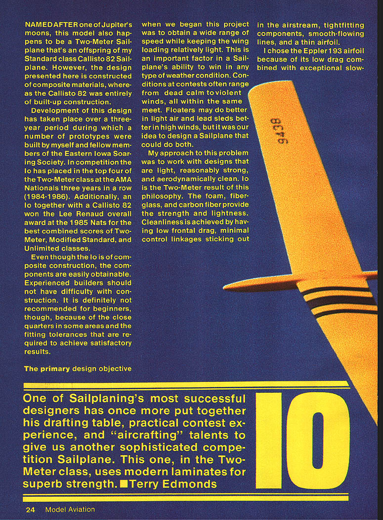
IO
Named after one of Jupiter's moons, this model is a Two-Meter sailplane and an offspring of my Standard-class Callisto 82 sailplane. The Callisto 82 was built-up wood construction; the design presented here (Io) is of composite construction.
Development of the Io took place over a three-year period during which a number of prototypes were built by myself and fellow members of the Eastern Iowa Soaring Society. In competition the Io placed in the top four of the Two-Meter class at the AMA Nationals three years in a row (1984–1986). Additionally, an Io together with a Callisto 82 won the Lee Renaud overall award at the 1985 Nats for the best combined scores of Two-Meter, Modified Standard, and Unlimited classes.
Although the Io is of composite construction, components are readily obtainable. Experienced builders should not have difficulty with construction. It is not recommended for beginners because of the close quarters in some areas and the fitting tolerances required to achieve satisfactory results.
The primary design objective
One of sailplaning's most successful designers has once more put together his drafting table, practical contest experience, and "aircrafting" talents to give us another sophisticated competition sailplane. This one, in the Two-Meter class, uses modern laminates for superb strength. — Terry Edmonds
The primary design objective was to obtain a wide speed range while keeping the wing loading relatively light. This balance is important to allow a sailplane to compete effectively in a variety of weather conditions: contest days often range from dead calm to strong winds. Floaters do better in light air and lead sleds in high winds; our aim was a sailplane that could do both.
My approach was to design something light, reasonably strong, and aerodynamically clean. Foam, fiberglass, and carbon fiber provide strength and lightness. Cleanliness is achieved by low frontal drag, minimal control linkages in the airstream, tight-fitting components, smooth-flowing lines, and a thin airfoil.
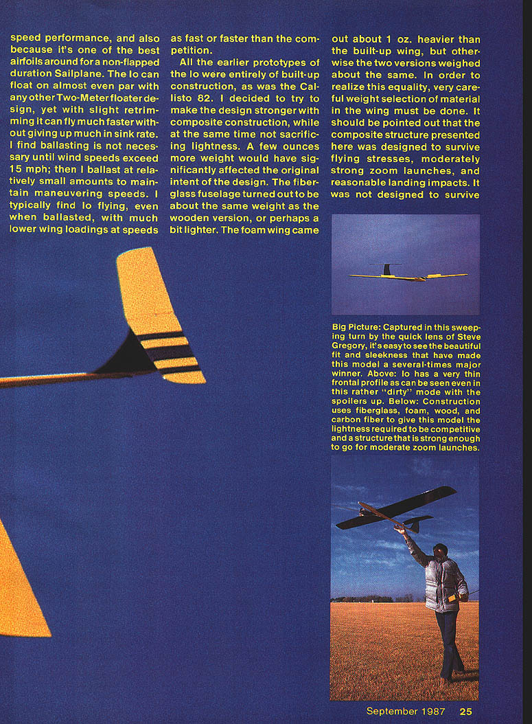
I selected the Eppler 193 airfoil for its low drag and excellent slow-speed characteristics. It is one of the best airfoils for a non-flapped duration sailplane. The Io can float nearly on par with most Two-Meter floaters, yet with slight retrimming it can fly much faster without losing much in sink rate. I find ballasting unnecessary until wind speeds exceed about 15 mph; then I add small amounts of ballast to maintain maneuvering speeds. Even when ballasted, Io often flies at lower wing loadings at speeds as fast as or faster than the competition.
All earlier prototypes of the Io and the original Callisto 82 were built-up construction. I switched to composite construction to increase strength without sacrificing lightness. The fiberglass fuselage turned out to be about the same weight as the wooden version or perhaps a bit lighter. The foam wing is about 1 oz heavier than the built-up wing; otherwise the two versions weigh roughly the same. Achieving that parity requires careful material-weight selection in the wing. The composite structure presented here is designed to survive normal flying stresses, moderately strong zoom launches, and reasonable landing impacts — it was not designed to survive spear-type landings.
On the contest scene there is about a 50/50 mix of flat-wing aileron sailplanes and other configurations. Flat-wing aileron sailplanes are inherently spiral-unstable and therefore more difficult to fly well, but their aileron maneuverability is better. Once the instability is overcome through practice, an aileron sailplane has an edge in precision/duration events; for this reason I chose a flat wing for Io.
Construction
It is assumed builders have at minimum built other sailplanes and possess a good understanding of basic model-building skills. Rather than provide step-by-step instructions, the following addresses important and unusual points.
Suppliers
- Viking Models
2026 Spring Lake Dr., Martinez, CA 94553
- Bob Sealy's Quality Fiberglass
521 96th Lane NE, Blaine, MN 55434
- Bob Violett Models
1373 N Citrus Rd., Winter Springs, FL 32708
Bob Sealy's Quality Fiberglass also markets foam wing cores and the carbon-fiber material used in the .007" x 1/4" carbon-fiber laminate embedded between wing skins. The carbon laminate consists of a layer of unidirectional carbon fiber embedded in a thin sheet of epoxy; it is available from various sources and can be bought in 1/4"-wide strips from Bob Violett Models, avoiding the need to slit the strip yourself. Other common materials are available from regular hobby sources.
Wing cores and shaping
- Wing cores are cut by the usual hot-wire method. Tic marks and templates account for leading-edge taper — be sure to line them up on the centerlines of the foam block; failure to do so will introduce twist into the wing panel.
- Bevel the core roots 3° so that the root rib fits flush with the fuselage. One method: prop the core up to the correct dihedral so the root is even with the edge of the building table and make a few passes over the edge with a sanding block. Another method: use a hot wire across two 87° templates.
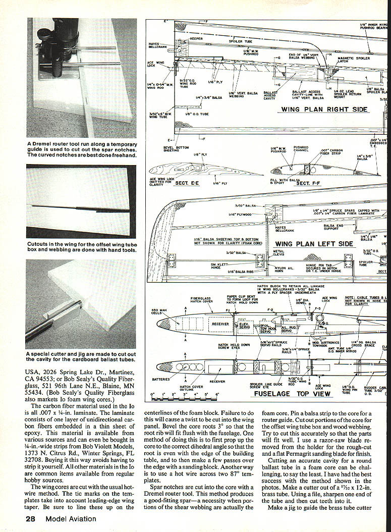
- Spar notches are cut with a Dremel router tool run along a temporary guide. Curved notches are best done freehand. Pin a balsa strip to the core as a router guide. Use a razor saw for rough cuts and a flat Permagrit sanding blade for finish.
Ballast tube and other core cutouts
- Cutting an accurate cavity for a round ballast tube in foam is best done with a homemade cutter: use a 1/2" x 12" brass tube, sharpen one end with a file and cut teeth into it, then make a jig to guide the cutter into the core at the proper angle. Twist the cutter by hand while applying slight inward pressure. Remove the cylindrical foam plug that breaks off inside the cutter. Try this on scrap foam first.
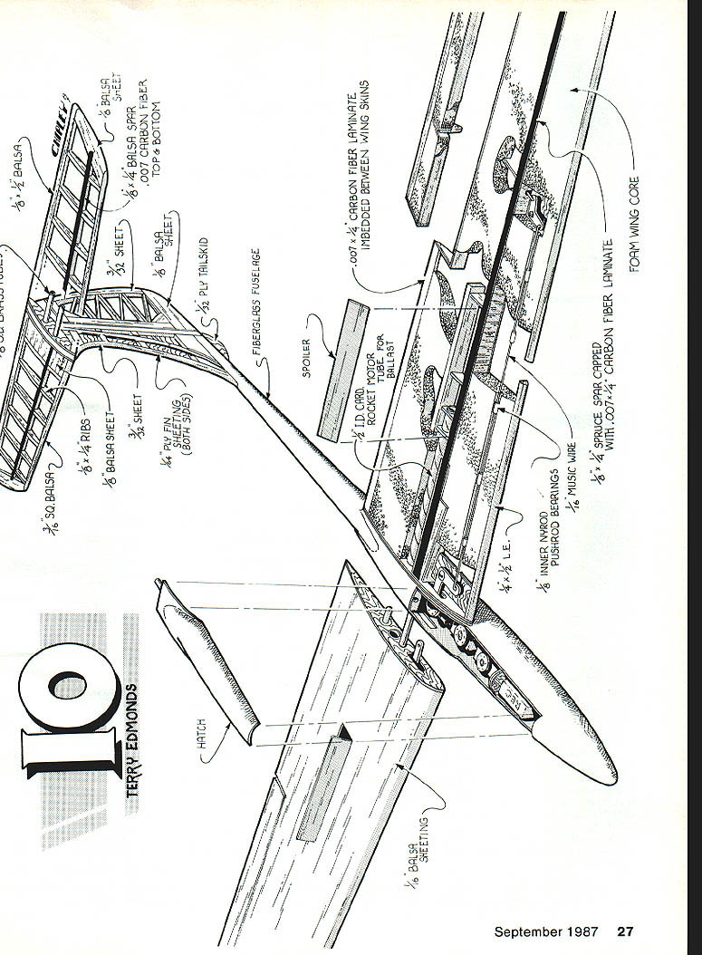
Spars and carbon-fiber caps
- Spruce spars are capped with .007" x 1/4" carbon-fiber laminate. Clean the carbon fiber with alcohol, then bond it to the spars with slow-set cyanoacrylate (CYA) glue. Handle the laminate with care — the fibers produce sharp splinters.
- Ensure the carbon-fiber strip has total glue coverage; bond voids could allow the carbon fiber to separate from the spar under compression stress.
Wing tube box and core assembly
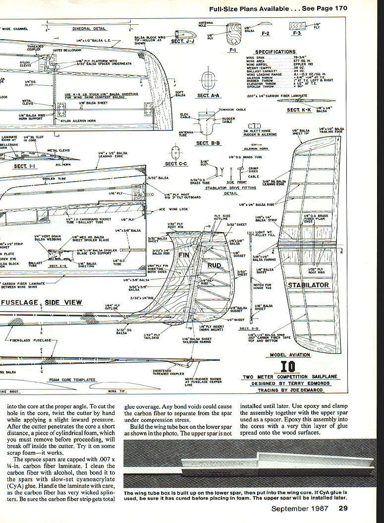
- Build the wing tube box on the lower spar. The upper spar is installed later. Use epoxy and clamp the assembly together with the upper spar used as a spacer.
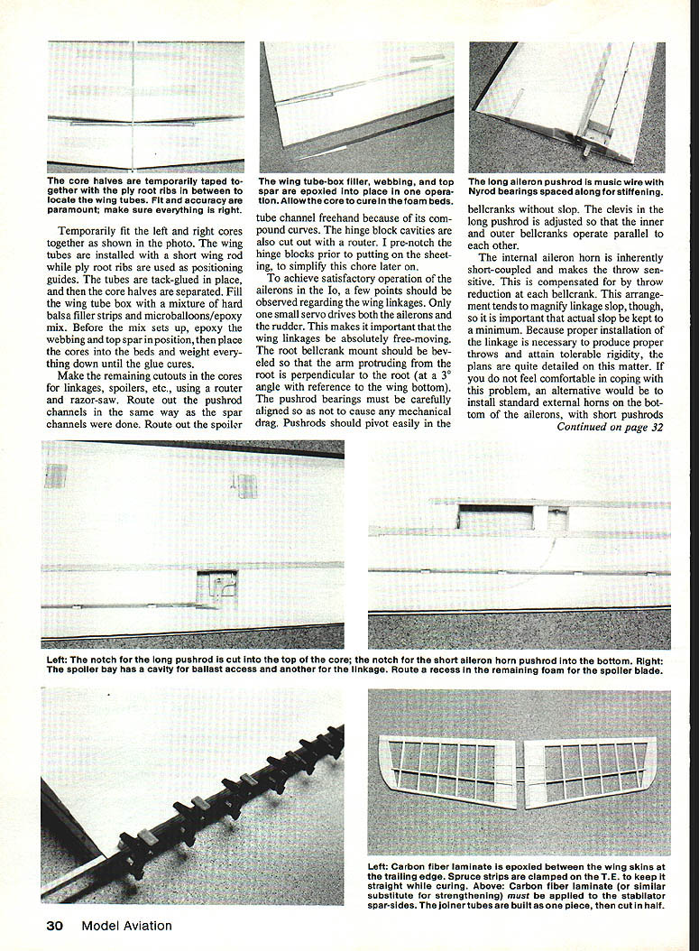
- Epoxy this assembly into the cores with a very thin layer of glue spread onto the wood surfaces. Temporarily tape the core halves together with ply root ribs between them to locate the wing tubes. Fit and accuracy are paramount.
- Install the wing tubes using a short wing rod while ply root ribs serve as positioning guides. Tack-glue the tubes in place, then separate the core halves. Fill the wing tube box with a mixture of hard balsa filler strips and a microballoons/epoxy mix.
- Before the mix sets, epoxy the webbing and top spar in position, then place the cores into the beds and weight everything down until the glue cures.
Final core machining and sheeting
- Make remaining cutouts for linkages, spoilers, etc., using a router and razor saw. Route pushrod channels as you did the spar channels. Route the spoiler tube channel freehand to follow compound curves.
- Pre-notch hinge blocks prior to sheeting to simplify later work.
- Epoxy the wing tube-box filler, webbing, and top spar into place in one operation and allow cure.
Wing skins, trailing edge, and reinforcement
- Any wing-skin adhesive can be used, but minimize added weight. The author uses Supertape (very light), though small areas of delamination have occurred.
- For additional trailing-edge strength, embed a strip of carbon-fiber laminate between the wing skins at the trailing edge. Glue it with epoxy as the top sheeting is applied. Clamp the trailing edge straight between spruce strips until cured to ensure a straight T.E.
- Even with carbon-fiber reinforcement, shrinking the covering can produce ripples in the thin trailing edge. Remedy by clamping the T.E. straight between balsa strips and reheating the covering with a heat gun.
Linkages and control
- To achieve satisfactory aileron operation, observe that only one small servo drives both ailerons and the rudder. Wing linkages must be absolutely free-moving.
- The root bellcrank mount should be beveled so that the protruding arm is perpendicular to the root (a 3° angle reference to the wing bottom). Pushrod bearings must be carefully aligned to avoid mechanical drag. Pushrods should pivot easily in the bellcranks without slop. Adjust the clevis in the long pushrod so inner and outer bellcranks operate parallel to each other.
- The internal aileron horn is short-coupled and makes the throw sensitive. Compensate with throw reduction at each bellcrank. This arrangement magnifies linkage slop, so keep slop to a minimum. The plans provide detailed instructions on this matter.
- If you are uncomfortable with the internal-horn arrangement, an alternative is to install standard external horns on the bottom of the ailerons with short pushrods exiting the bottom of the wing.
- Bellcranks are built up from 5/32" balsa with a plywood spacer underneath. A bent fiberglass "paper cup" is used as noted for reinforcement where required.
- A hatch block retains all linkage in the wing.
Aileron connection and differential
- Aileron connect/disconnect is accomplished by L-shaped wires from the servo engaging the wing bellcranks. To connect the ailerons, drop the wires into the bellcrank holes; wires are retained by a block in the bottom of the hatch.
- The hatch is secured by rubber bands stretched from one screw eye through a paper-clip loop to the other screw eye in an inverted V-shape.
- Proper aileron differential is achieved by selecting the correct connection point on the servo wheel. Start by attaching couplers near the recommended spot and fine-tune by trial-and-error drilling of holes in the wheel until the desired differential is obtained. Expect to sacrifice a couple of wheels during setup.
- Small turnbuckles in the L-wires provide very fine trim adjustments. Nylon turnbuckles that were once used may be unavailable; metal turnbuckles can be adapted.
Stabilator and joiner
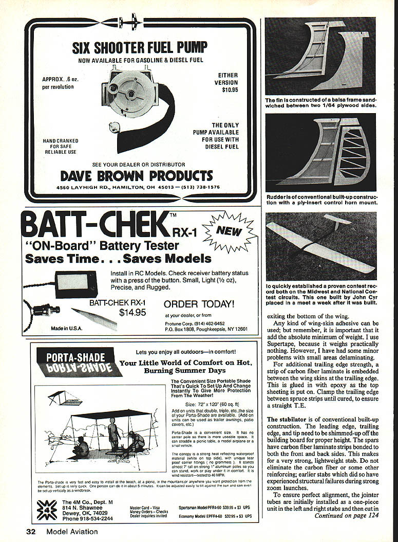
- The stabilator is conventional built-up construction. The leading edge, trailing edge, and tip must be shimmed off the building board for proper height.
- Spars have carbon-fiber laminate strips bonded to both front and back sides for strength and lightness. Do not eliminate carbon-fiber reinforcement — earlier stabs without it have experienced structural failures during strong tows and launches.
- For perfect alignment, install the joiner tubes initially as a one-piece unit in the left and right stabs and then cut them in half.
Fuselage, tow hook, and finishing
- A 1/8" fiberglass fuselage can be obtained from Viking Models or Bob Sealy's Quality Fiberglass (see supplier addresses above).
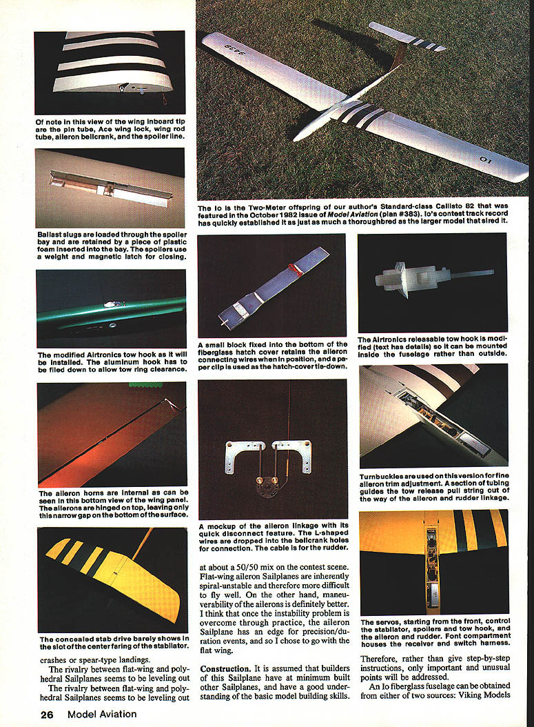
- The wing inboard tip uses a pin tube and an Ace wing lock. The wing rod tube and aileron bellcrank are located as shown on the plans.
- The spoiler bay is used to load the spoiler line and ballast slugs; retain ballast with a piece of plastic foam inserted in the bay. Spoilers use a weight-and-magnetic latch for closing.
- Tow hook: I modified an Airtronics releasable tow hook to mount inside the fuselage to reduce drag. Steps:
- Bevel the lower frame edges with a Dremel grinder.
- Cut a slot in the bottom of the fuselage to allow the hook to protrude from the inside.
- Sand down any fiberglass bumps inside the fuselage in the tow-hook area so the hook sits as low as possible.
- File the aluminum hook down to provide adequate tow-ring clearance.
- Mount screws and nutplates as usual. If using the capture feature, add a 1/4" wire pin to the capture latch to fill the gap made by filing down the hook.
Radio installation
- Radio installation must follow the plans and photos closely because of limited space. The front control order is: stabilator, spoilers, tow hook, aileron, rudder.
- The front compartment houses the receiver, switch, and harness.
- Section tubing guides the tow-release pull string out of the way of the aileron-rudder linkage. Ensure all control runs are free and that the tow-release operates smoothly before flight testing.
Spoilers, lines, and ballast
- Spoilers are hinged with a strip of MonoKote ironed on the top side.
- Spoiler lines are made from Goldberg 1/8" control line with loops tied in the ends that slip over a spindle on the servo arm. The spindle is formed from an eyelet attached to the servo arm. Thread the lines through a screw eye to guide them directly to the servo. At the spoiler end the lines are attached to the horns with round toothpicks.
- The spoiler servo also pulls the tow-hook release. Fit a nylon tube to route the line out of the way of other linkages.
- Ballast: use 1/2" O.D. x 2" brass tube sections filled with lead. Lead shot can be epoxied in the tubes or lead can be melted and poured into the tubes — if melting lead, take proper precautions (molten lead fumes are deadly). Do not attempt this without full understanding of the hazards.
Covering and finish
- I use Super MonoKote for the finish on all surfaces except the fuselage, which is painted. Whatever finish is chosen, keep weight buildup to a minimum. Paint weight on the fuselage is less of a concern because of the small surface area.
- If covering shrink produces ripples in the trailing edge, clamp the trailing edge straight between balsa strips and reheat the covering with a heat gun to smooth it.
Trimming and flying
- Set initial control-surface throws as per the plans, though throws may feel sensitive for some pilots.
- Test the model with hand tosses to get the feel, then fly on the line. Launches can be high-speed with moderately strong zoom releases if desired.
- Experiment with different trim settings to find usable speeds for thermal searching, thermalling, and getting out of sink.
- Test spoilers at altitude — they are very effective.
- Be aware that Io's very thin frontal profile tends to disappear when coming directly at or going directly away from you, even at moderate distances; this can be unnerving until you get used to it.
- Io performs well on the slope, can ride small hills, and when ballasted can handle strong lift. It is highly maneuverable and enjoyable to fly.
Transcribed from original scans by AI. Minor OCR errors may remain.

