
IRONSIDE
L. F. Randolph
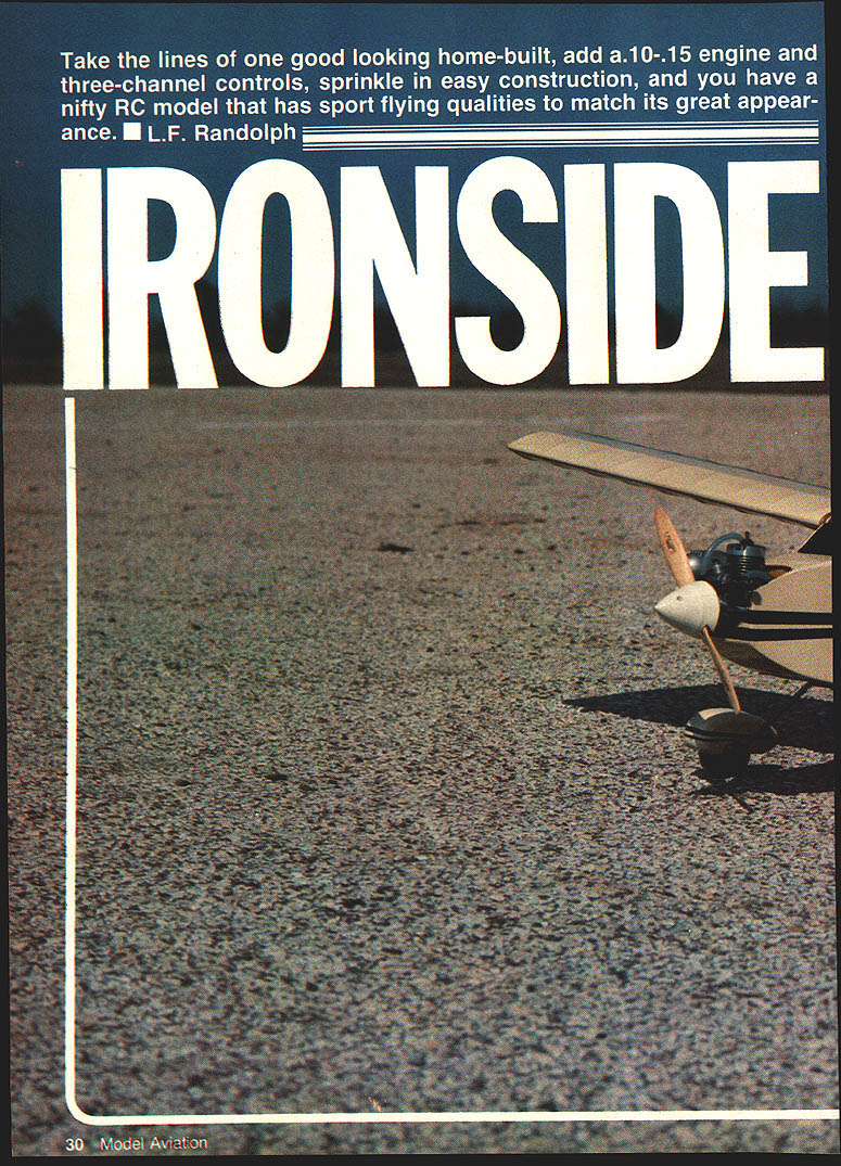
Take the lines of one good-looking home-built, add a .10–.15 engine and three-channel controls, sprinkle in easy construction, and you have a nifty RC model that has sport-flying qualities to match its great appearance.
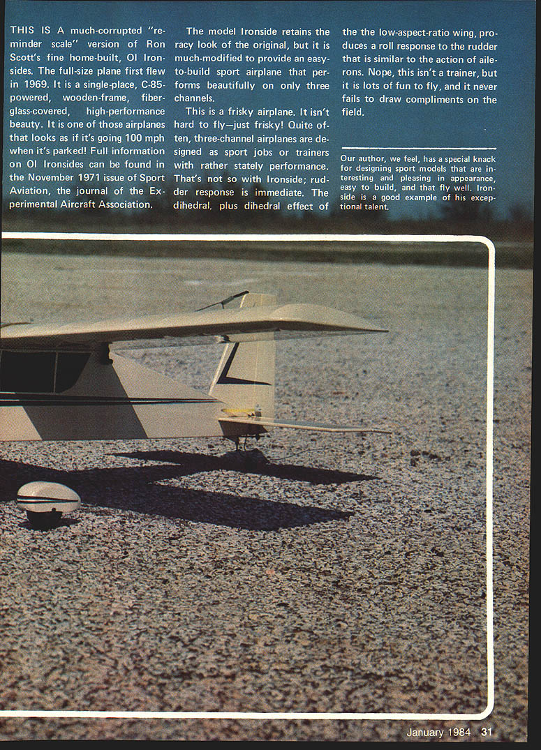
This model is a somewhat compacted "reminder-scale" version of Ron Scott's first home-built, Ol Ironsides. The full-size plane first flew in 1969; it is a single-place, C-85-powered, wooden-frame, fiberglass-covered, high-performance beauty. Full information on Ol Ironsides can be found in the November 1971 issue of Sport Aviation (the EAA journal). The model retains the racy look of the original but is modified for easier construction and three-channel sport performance.
Ironside is frisky rather than sedate. Rudder response is immediate and, because of the dihedral and the low-aspect-ratio wing, rudder inputs produce a pronounced roll similar to ailerons. It is not a trainer, but it is forgiving and great fun to fly. Most flying is done at less than half throttle; a .10 engine will be adequate, while an OS .15 provides spirited climb performance. If you fly from grass, omit wheel pants and use larger wheels.
Performance highlights
- Takeoffs and landings are straight down the runway with almost no rudder correction required.
- Climb-out with an OS .15 can be very steep (hot-climbs reported around 65°) and prolonged.
- The model will snap in its own length and, with proper rudder/elevator coordination, rolls are almost axial.
- In the event of a malfunction (e.g., a stuck rudder servo), the airplane's natural stability can allow safe recovery and landing.
---
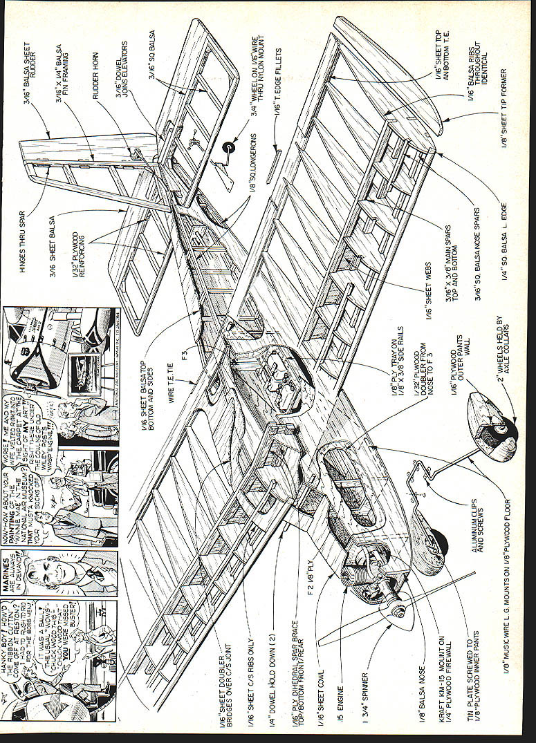
Wing
Materials and parts
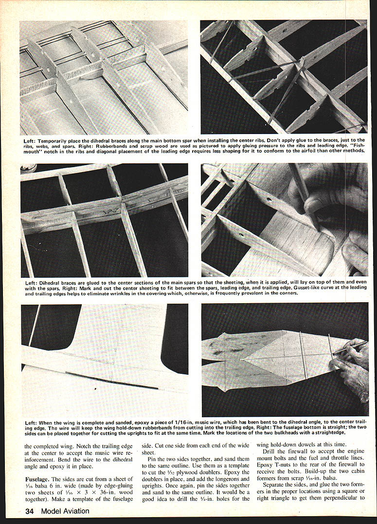
- Slice 20 ribs from medium to light balsa and pin them together into a block for sanding to the same shape.
- Select four ribs as center-section ribs and remove 1/16 in. from the tops and bottoms; widen the main-spar notch to accept 1/16-in. plywood dihedral braces.
- Cut webs from vertical-grain 1/16-in. hard balsa.
- Dihedral braces: 1/16-in. plywood.
- Trailing-edge sheeting: 1/16-in. medium balsa sheet.
- Spars: strip from 3/32-in. sheet (or purchase to size).
- Leading edge: 1/4-in. square wood.
- Trailing-edge cap: 1/8-in. square.
- Reinforcement: a short piece of 1/16-in. music wire for the center trailing edge; a 6-in. music-wire hold-down bent to the dihedral angle is recommended.
Building steps
- Cover the plan with plastic wrap. Pin the main spar and bottom trailing-edge sheeting in place over the plan.
- Add the second center-section rib (with the enlarged notch), glue it in place, then add a web outboard of it followed by the first regular rib. Continue alternating webs and ribs out to the tip.
- Bevel the webs to the dihedral angle as required and install them along the center rib.
- Glue the top main spar in place, making sure it is attached to the webs and ribs.
- Install the leading edge and the top trailing-edge sheeting at this time.
- Remove the half-wing from the plan and build the other half the same way.
- Join both halves using the dihedral braces; the braces should fit snugly into the enlarged notches in the center-section ribs.
- Add the top trailing-edge cap, glue the tips in place, and sand the wing smooth.
- Epoxy a piece of 1/16-in. music wire, bent to the dihedral angle, to the center trailing edge to protect the trailing edge from wing-hold rubber bands cutting in.
Notes
- When finished, cover the wing with MonoKote (or other iron-on film) and hinge surfaces with the covering material per the manufacturer's instructions.
---
Fuselage
Materials and initial cuts
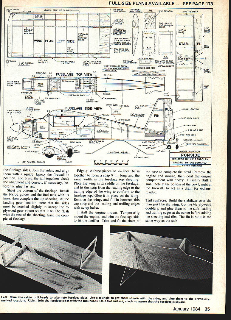
- Sides: cut from 1/8-in. balsa, 6 in. wide (edge-glue two 1/16 x 3 x 36-in. sheets together).
- Make a template of the fuselage side and cut one side from each end of the wide sheet so the grain and shapes match.
- 1/8-in. plywood doublers for cockpit/cabin area.
- Fuselage bottom: 1/16-in. sheet.
Construction steps
- Pin the two sides together and sand them to the same outline. Use them as a template to cut the plywood doublers.
- Epoxy the doublers in place, then add longerons and uprights. Keep the sides pinned together and sand to the final outline.
- Drill 1/4-in. holes for the wing hold-down dowels at this stage.
- Drill the firewall for engine-mount bolts and fuel/throttle lines. Epoxy T-nuts to the rear of the firewall to accept the bolts.
- Build the two cabin formers from scrap 1/8-in. balsa and glue them into position square to the sides.
- Separate the sides if necessary and glue the two formers permanently in place. Cut the fuselage bottom from 1/16-in. sheet and glue it in place.
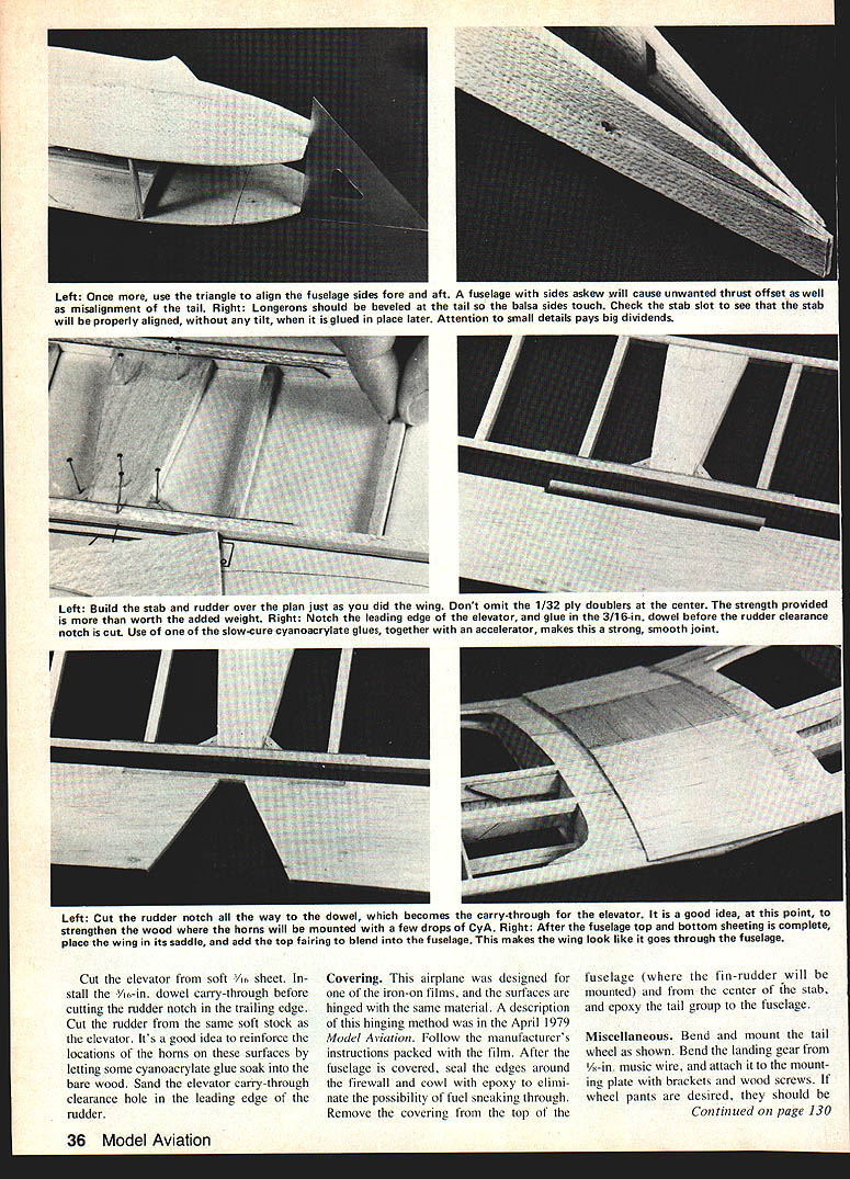
- Join the sides, align them with a square, epoxy the firewall in position, and bring the tail together; check alignment before glue sets.
- Sheet the bottom of the fuselage. Install Nyrod guides and the fuel tank with its lines, then complete the top sheeting.
- At the landing-gear location, notch the sides slightly so the 1/8-in. plywood gear mount will be flush with the sheeting. Sand the completed fuselage.
Top cap and nose
- Edge-glue three pieces of 1/16-in. sheet balsa to form a strip about 9 in. long (same width as the fuselage top sheeting). Place the wing in its saddle, fit this strip from leading edge to trailing edge of the wing so it conforms to the fuselage top, and glue it in place on the wing. Remove the wing and fill in between this cap strip and the leading and trailing edges with scrap balsa.
- Install the engine mount, temporarily mount the engine, and trim the fuselage sides to clear the muffler. Trim and fit the nose sheet to complete the cowl.
- Remove engine and mount, coat the engine compartment with epoxy, and drill a small drain hole at the bottom of the cowl near the firewall to evacuate exhaust residue.
Notes
- The fuselage bottom is straight; having the two sides together while cutting uprights helps ensure a good fit.
- Epoxy the wing hold-down dowels in place once their positions are final.
---
Tail surfaces
Construction
- Build the stabilizer over the plan in the same manner as the wing.
- Cut and glue 1/32-in. plywood doublers to the stab’s leading and trailing edges at the center before adding the sheeting and ribs.
- Build the fin the same way as the stabilizer.
- Cut the elevator from soft 1/16-in. sheet and install the 1/16-in. dowel carry-through before cutting the rudder notch in the stabilizer trailing edge.
- Cut the rudder from the same soft 1/16-in. stock.
- Reinforce servo-horn locations on elevator and rudder by letting cyanoacrylate (CA) soak into the bare wood.
- Sand the elevator carry-through clearance hole in the rudder leading edge.
---
Covering
- This airplane was designed for iron-on film covering (MonoKote or similar). Hinge surfaces using the covering material; a hinging method was described in Model Aviation (April 1979). Follow the film manufacturer's instructions.
- After the fuselage is covered, seal edges around the firewall and cowl with epoxy to prevent fuel seepage.
- Remove covering where the fin/rudder will be mounted (top of fuselage) and from the center of the stabilizer; epoxy the tail group to the fuselage after these areas are uncovered.
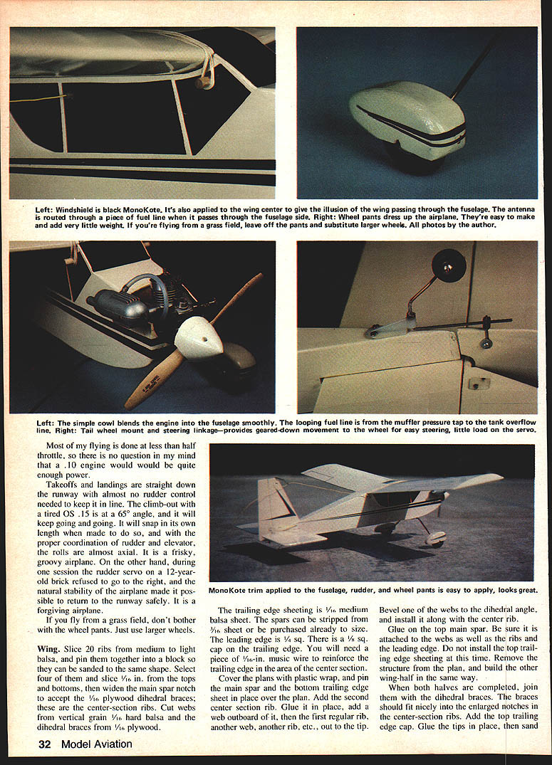
- Windshield: cover with black MonoKote.
- Apply black MonoKote to the center of the wing to give the illusion of the wing passing through the fuselage.
- Route the antenna through a short length of fuel line that passes through the fuselage side.
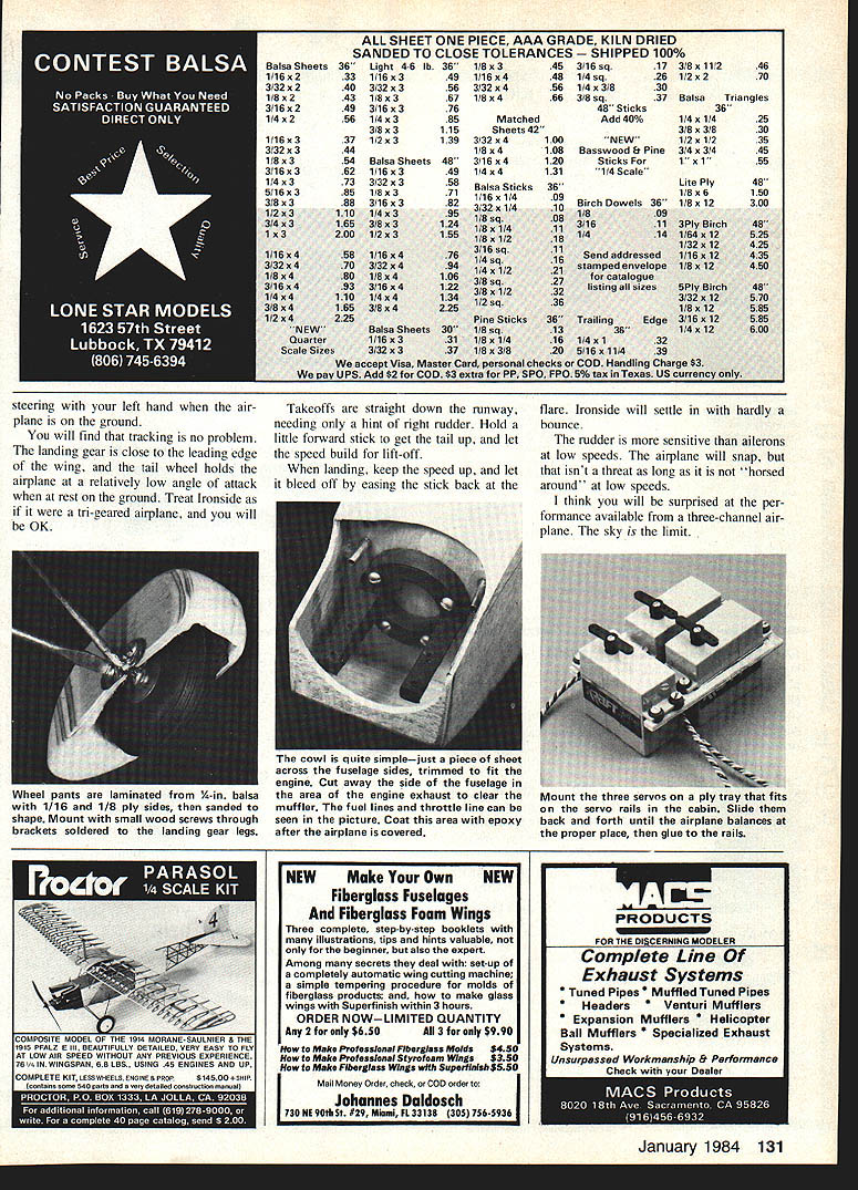
Wheel pants and cowl
- Wheel pants dress up the model; they are easy to make and add little weight. If flying from grass, omit pants and use larger wheels.
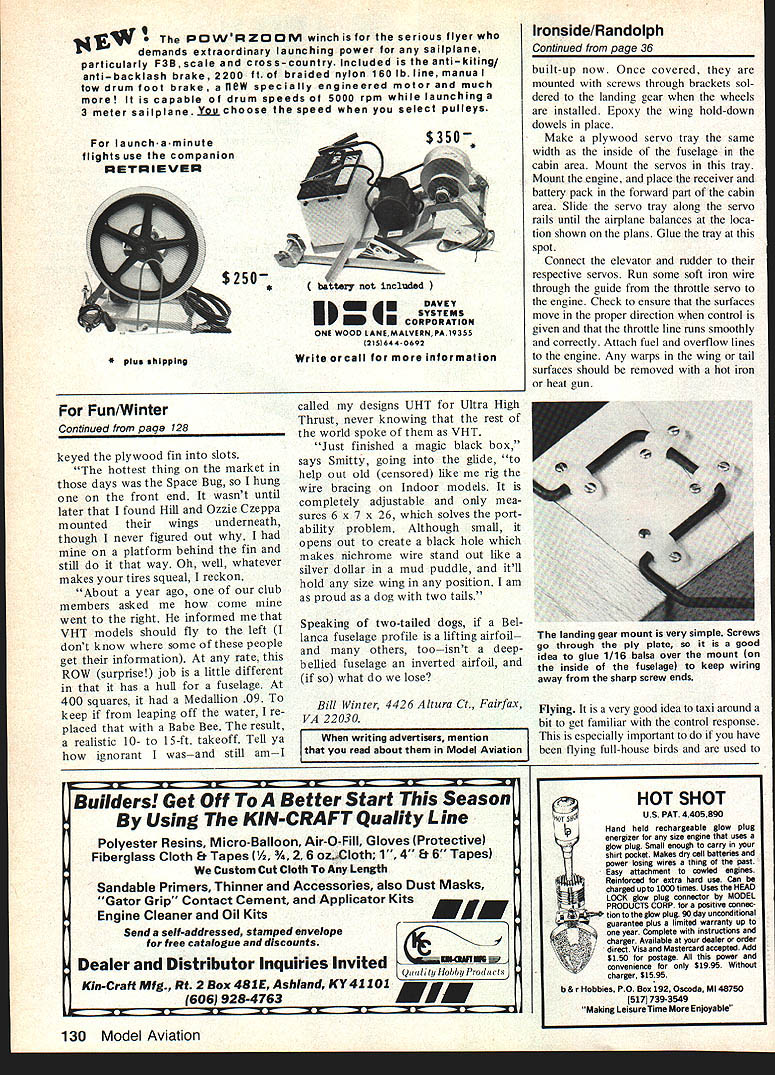
- Wheel pants, once covered, are mounted with screws through brackets soldered to the landing gear.
- The simple cowl should blend the engine and fuselage smoothly; loop the fuel line and arrange the muffler pressure tap and tank overflow line so they are neat and unobtrusive.
---
Miscellaneous / Hardware
Landing gear and tailwheel
- Bend the landing gear from 3/32-in. music wire and attach it to a 1/8-in. plywood mounting plate with brackets and wood screws.
- Bend and mount the tailwheel and steering linkage to provide a geared-down movement of the wheel for easy steering with little load on the servo.
- Cover the inside of the fuselage over the gear mounting screws with 1/16-in. balsa to keep wiring away from sharp screw ends.
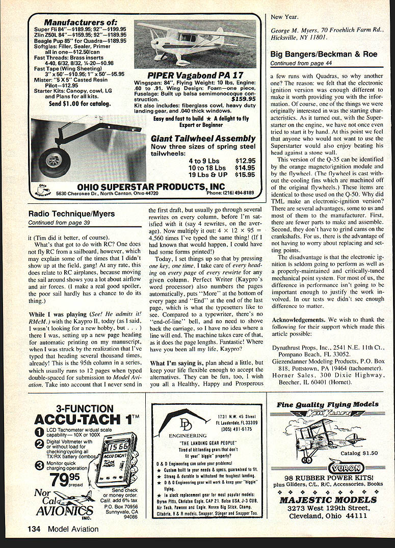
Servos, radio and balance
- Make a plywood servo tray the same width as the inside of the fuselage in the cabin area and mount the servos in it.
- Mount the engine and place the receiver and battery pack forward in the cabin area.
- Slide the servo tray along the rails until the airplane balances at the location shown on the plans, then glue the tray in place.
- Connect elevator and rudder linkages to their servos. Run soft iron wire through a guide from the throttle servo to the engine; check that the throttle runs smoothly.
- Attach fuel and overflow lines to the engine; seal and check for leaks.
- Epoxy the wing hold-down dowels in place.
Final checks and straightening
- Ensure all surfaces move in the proper directions for control inputs.
- Remove any warps in wing or tail surfaces with a hot iron or heat gun.
- Make sure all hardware is secure and that the throttle and fuel systems run freely.
---
Flying
Preflight
- Taxi around to get familiar with the control response—especially important if you are used to full-house models with a lot of authority.
- Check control throws and correct surface movement directions before flight.
General flying
- Most flying is done at less than half throttle; a .10 engine will be adequate for gentle sport flying, while a .15 will give more spirited performance.
- Takeoffs: straight down the runway with only a hint of right rudder. Hold a little forward stick to get the tail up and let speed build for lift-off.
- Climb-out: steady; the OS .15 will keep it going. The model will snap its own length with proper rudder/elevator coordination.
- Rolls: almost axial when properly flown.
- Landings: keep speed up, then bleed off by easing the stick back at the flare; Ironside settles in with hardly a bounce.
- Rudder is more sensitive than ailerons at low speeds; avoid aggressive high-rate maneuvers at low speed.
Safety and handling notes
- The model is frisky but forgiving. In one reported case a rudder servo failed to move one direction; the model’s stability allowed a safe return and landing.
- If operating from grass strips, omit wheel pants and fit larger wheels for improved ground handling.
---
I think you'll be surprised at the performance available from a three-channel model—Ironside is fast-looking, fun to build, and a lively, forgiving sport flier.
Transcribed from original scans by AI. Minor OCR errors may remain.

