
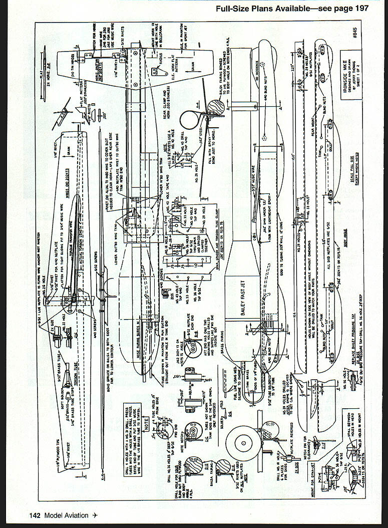

Ironside
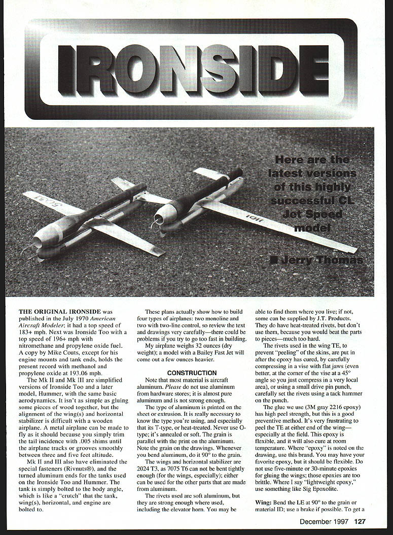
The original Ironside was published in the July 1970 American Aircraft Modeler and had a top speed of 183+ mph. Next came Ironside Too with a top speed of 196+ mph using nitromethane and propylene oxide fuel. A copy by Mike Coutts — except for his engine mounts and tank ends — holds the present record with methanol and propylene oxide at 193.06 mph.
The Mk II and Mk III are simplified versions of Ironside Too (and of a later model, Hummer) using the same basic aerodynamics. Alignment of the wing(s) and horizontal stabilizer is difficult with wood; a metal airplane allows fine trimming of tail incidence with .005" shims until the airplane tracks or grooves smoothly between three and five feet altitude.
Mk II and Mk III eliminate special fasteners (rivnuts) and the turned-aluminum tank ends used on Ironside Too and Hummer. The tank is simply bolted to the body angle, which acts like a "crutch" that the tank, wings, horizontal, and engine are bolted to.
These plans show how to build four types of airplanes: two monoline and two with two-line control. Review the text and drawings carefully — rushing can cause problems. My airplane weighs 32 ounces dry; a model with a Bailey Fast Jet will be a few ounces heavier.
Construction
#### Materials
- Use aircraft-grade aluminum only. Do not use aluminum from hardware stores; it is almost pure aluminum and not strong enough.
- Know the alloy designation and use T-type (heat-treated) material. Never use O-type (annealed/soft).
- Orient the grain parallel to the span (and as shown on the drawings). Whenever you bend aluminum, bend 90° to the grain.
- Wings and horizontal stabilizer: 2024-T3 is recommended (7075-T6 cannot be bent as tightly for the wings). Either alloy may be used for other parts.
- Rivets: use soft aluminum rivets (they are strong enough where used, including the elevator horn). Do not use heat-treated rivets — they are too hard and will damage parts.
#### Rivets and Epoxy
- Rivets used in the wing trailing edge (TE) to prevent peeling of skins should be installed after the epoxy has cured. Compress the rivet area carefully in a vise with flat jaws (a corner vise at a 45° angle works well) to compress only a very local area, or use a small drive-pin punch. Set rivets with a tack hammer and punch.
- Use a flexible epoxy with high peel strength. The author recommends 3M Gray 2216 epoxy (it cures at room temperature and has high peel strength). Do not use five-minute or 30-minute epoxies for gluing wings — they are too brittle. For lightweight epoxy joints, consider something like Sig Epoxolite.
- Roughen adhesive surfaces (80–100 grit) and clean with MEK (methyl ethyl ketone) or acetone before bonding.
#### Wing construction
- Bend the leading edge (LE) at 90° to the grain. Use a brake if possible.
- To get a good LE radius, compress the wing between two pieces of plywood with a piece of .050–.060" aluminum inside the wing so you don't compress it completely flat.
- Open the wing carefully with two thin pieces of material to obtain the proper TE fit. You want the airfoil thickness inside the wing to be approximately 5/16" at the center (inboard) and 1/8" at the tip so the wing will slide onto the spar easily. Adjust each end until you have a good fit. It's better to have it a bit larger — easier to compress after gluing than to open up a too-tight TE.
- Prepare the TE: rough up the inside with 80–100 grit sandpaper and clean with MEK or acetone.
- Make a gluing jig: glue a 1/16" x 1/8" basswood strip to a flat board to rest the TE on; place another 1/16" x 1/8" piece about 1/2" away to hold a 1/16" aluminum clamp strip. Use a stop to butt the LE so the TE just laps onto the 1/16" x 3/8" wood by about 1/16".
- Protect the wood and clamp surfaces with good plastic tape and a light coat of paste wax so the wing won't stick. Glue the wing with the upper surface up; the lower surface should just touch the board.
- This bonding orientation provides the desired twist: incidence at the center and 0° at the tip (essential on the Mk III and effective on the Mk II).
- If you find the wing too difficult to make, some modelers produce metal wings (e.g., Chris Sackett).
#### Flying wire and control system
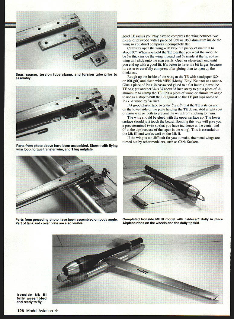
- The flying wire attaches directly to the airplane; the wire wraps around a lug nutplate and is retained by a 6-32 Allen screw. The screw and nutplate take the pull of the wire; the nutplate is retained by a 1/8" aluminum spacer.
- The torsion-transfer wire is held to the flying wire with copper wire (.015–.020") and is soft-soldered; finish the end per AMA rule book practice.
- A wingtip guide simplifies installing the flying wire — slip it through the slot then straighten it out; with the wing on, it cannot move.
- The control system used on Speed models functions largely as a trim tab; these models are designed to be stable and track well with little continuous control input. The torsion wire is fairly short; a long elevator horn provides leverage so in-flight control closely matches ground setup.
#### Tank and fuel system
- Tank material: anodized 6061-T6 tubing with .028" wall. Tank ends are turned from Delrin (or equivalent). Tank ends and holes in the sidecar/dolly bolts are the only turned parts required on a lathe.
- O-rings: ethylene propylene, 1.25" diameter and .070" thick. Bearings, Inc. part number 07-022. If not available locally, try a hydraulic supply company or J.T. Products.
- Ethylene propylene is resistant to methanol and propylene oxide.
- Installing the 1/8" brass tubing in the tank end: fillers are straight and fuel lines have a gentle bend. A 1/8" pressure line has been used successfully, though some prefer 3/32". If using 3/32", use a #43 drill hole through the front tank end (to avoid enlarging the hole in the Fast Jet cowl).
- Minimize turbulence in front of the intake — the cowl shape is not critical as long as it is a smooth contour.
- Fuel fillers should have enough clearance in the balsa fairing so you can slip silicone tubing off one tube, attach a fuel bulb to the other, and fill with the airplane vertical (nose up). When fuel comes out of the free tube, the tank is full; then replug the tube. You may cover the filler with vinyl electrical tape.
- Before flight, wrap a piece of tape around the threaded end of the tube and the lock ring. If the tape is "cut" after flight it indicates a pressure leak from the combustion chamber and a power loss.
- Lap the forward (threaded) end of the tube and the back of the lock ring on wet-or-dry silicon carbide on a flat plate or piece of glass so they seat flat.
- When installing tank ends, use a small tube of dielectric tune-up grease to coat the O-ring so it slides easily. Deburr the inside edge of the tube with a bearing scraper or deburring tool to aid O-ring installation.
- Remove the forward balsa fairing and the two screws into the tank angles to remove the tank easily for cleaning or inspection.
#### Balance and engine mounting
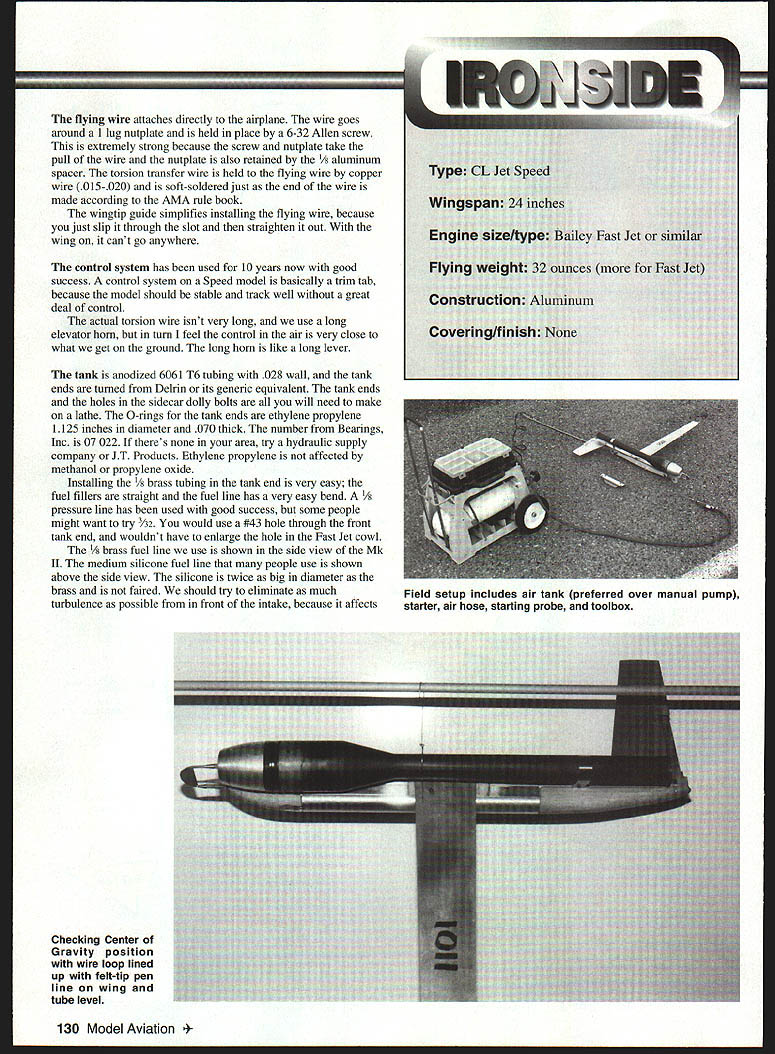
- To position the engine correctly, mount it loosely in the rear mount so it can be moved. Use a large rubber band to hold the forward end of the engine.
- Make a wire loop about 1½" in diameter with a U-bend so it can be installed and removed easily. Cut the wire about eight inches long and make a small loop to hold in your fingers.
- Mark the center-of-gravity (CG) location on the wing with a fine felt-tip pen. Move the engine until the wire loop lines up with the CG mark on the wing with the engine level.
- When mounting the engine, ensure it is parallel with the top of the body and also parallel in the vertical plane. Correct alignment is essential for smooth flight.
#### Dolly and landing gear
- The Mk II can use the sidecar dolly with the weight shown in the drawings; the Mk III should have a piece of lead between the aluminum and steel held in by the two screws inside the wire. Total weight of the three pieces should be about eight ounces.
- Dolly pins going into the body angle should not protrude more than 1/4" beyond the end of the bolts.
- After assembling the dolly, install it and check that each pin inserts and withdraws without binding. Drill a same-size hole 3/8" forward of the aft hole, then cut between the holes with a jeweler's saw to leave a 7/16" long slot. Clear the local balsa and plywood to ensure it will clear the rear tank mount.
- Tie a brightly colored streamer to the outboard end of the dolly to make it easier to find after flight.
- With the wheels shown, the Mk II will take off without a dolly: the wheels are in line with the engine center so it tracks straight. Wheels used by the author are made by Glenn Lee.
- If using skids, use the dolly shown (skids are inside the engine center and the model will pivot about the skid otherwise). Skids can be reversed front-to-back when one end wears to extend life.
#### Flying, starting, and handling
- Jets don't react as quickly as propellers; they take some getting used to, but should largely fly themselves with little correction needed.
- If you've never flown monoline before, build a trainer that flies six laps in 9.5–10 seconds (about 180–190 mph on a 70-foot line) to learn the feel. Avoid overthinking in flight — reflexes should drive control.
- If new to jets, find an experienced person to help with starting and initial flights.
- When starting a jet, some use a plug and ground to the engine; the Fast Jet comes with a plug. Attach alligator clips from the starter box to the plug and ground the other clip to the airframe. Remove sharp points from clip teeth so you can pull them off easily.
- The author prefers a probe rather than the plug so the airplane can be launched immediately. If the probe pops out of the engine without starting, the mixture is too rich — reduce metering by .001 at a time. If the engine sounds rough ("like a sick cow"), stop immediately — the engine is lean and you risk damaging parts; increase metering by .001 at a time.
- When starting out, try a #44 metering jet; after dialing in metering the engine will often start without priming.
- Use an air tank for pumping rather than a hand pump if possible; it is easier on the crew. The Fast Jet probe guide helps center on the flojector.
- When the engine starts, release the model as soon as it will fly but don't rush or you may let go too soon. Ensure the model is pointed straight ahead (or slightly outside) and let go.
- After flight, pick the airplane up by the wing close to the body: the exhaust tube and intake can be hot, and never stand behind the airplane when picking it up — raw fuel in the tube can spill.
#### Metering jets and fuel recommendations
- The Bailey Fast Jet comes with meters .037, .038, .039, and .047. They were designed for Sidewinder-type airplanes with the tank pickup 2" inboard from the engine center. The Mk II and Mk III have the fuel pickup 3/8" inboard, so different meters are typically used.
- The author has been running .041–.044 metering jets depending on weather. Earl Bailey offers .040–.046 meters which, together with included meters, provide a set from .037–.047. Temperature, humidity, and altitude affect required metering.
- Note: pressure metering may be enlarged to .046 with a Du-Bro 5/32 pressure tap.
- The Bailey Fast Jet will run on pressure as delivered; Stock Jet and Dyna Jet type engines typically run on suction with metering in the .055–.060 range.
- Run the engine as rich as possible; if too rich, reduce metering .001 at a time. Running too lean can burn or chip a valve which may require engine teardown and valve lapping.
- Tank volume: 200 cc is sufficient for a good official flight running rich. Use a 500 cc fuel bottle and mix 400 cc methanol and 100 cc propylene oxide (allows two test flights and some topping off). You may need to restart a few times during testing to find correct metering.
- Methanol handling:
- Methanol is hygroscopic and draws water easily. Check methanol with a hydrometer: 100% methanol reads about .795. Different batches may vary (e.g., 100% vs. 92%).
- Water in fuel will reduce speeds or prevent starting.
- If the engine will not start and other checks are good, blow the tank out — lines can plug, and condensation can form in the tank under certain weather conditions. Blow out with a tire pump and fill immediately.
#### Miscellaneous notes
- The author uses only Allen (hex) screws; they have proven reliable and strong. Use button-head Allen screws except for one flat-head in the inboard end of the spacer and one on the torsion-tube clamp on Mk II and Mk III monoline airplanes.
- Some modelers see button heads and wheels as drag sources, but experienced aerodynamicists report it is negligible.
- When installing tank tubing and lock rings, lap the mating surfaces so they seat flat and use dielectric grease on O-rings for easier assembly.
Sources and contacts
- Wings / Speed Times / North American Speed Society (Chris Sackett)
Box 82294, North Burnaby B.C. V5C 5P7, Canada (604) 299-4500
- Wheels: Glenn Lee
819 Mandrake Dr., Batavia IL 60510
- Bailey Fast Jet, Stock Jet, Metering Jets: Bailey Machine Service
633 West Parker, Houston TX 77091 (713) 694-7017
- Monoline handles: George W. Brown III
5235 S. Kyrene Rd., Suite #7, Tempe AZ 85283 (602) 491-0902 (days)
- .031 x 70-foot monoline: Ned Morris
9044 Rushmore Blvd. South, Indianapolis IN 46234 (317) 271-1231
- Materials for Ironside Mk II and Mk III: J.T. Products
9215 33rd St. East, Edgewood WA 98371 (206) 845-1269
- Nutplates: Spencer Aircraft
(800) 424-1160
- 3M Gray 2216 epoxy: 3M
(800) 362-3550 (call for dealer nearest you)
Author contact:
- Jerry Thomas
9215 33rd St. East, Edgewood WA 98371
Transcribed from original scans by AI. Minor OCR errors may remain.

