
Isaac's Fury
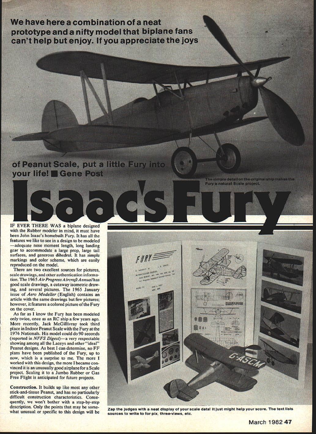
If ever there was a biplane designed with the rubber modeler in mind, it must have been John Isaac's homebuilt Fury. It has all the features we like to see in a design to be modeled — adequate nose moment length, long landing gear to accommodate a large prop, large tail surfaces, and generous dihedral. It has simple markings and color scheme, which are easily reproduced on the model.
There are two excellent sources for pictures, scale drawings, and other authentication information. The 1965 Air Progress Aircraft Annual has good scale drawings, a cutaway isometric drawing, and several pictures. The January 1965 issue of Aero Modeller (English) contains an article with the same drawings but few pictures; however, it features a colored picture of the Fury on the cover.
As far as I know the Fury has been modeled only twice: once as an RC ship a few years ago, and more recently Jack McGillivray took third place in Indoor Peanut Scale with the Fury at the 1976 Nationals. His model could do 90 seconds (reported in NFFS Digest) — a very respectable showing among the Laceys and other "ideal" Peanut designs. As best I can determine, no free-flight (FF) plans have been published of the Fury up to now, which is a surprise. The more I worked with this design, the more I became convinced it is an unusually good airplane for a scale project. Scaling it to a Jumbo Rubber or Gas Free Flight is anticipated for future projects.
Construction
It builds up like most any other stick-and-tissue Peanut and has no particularly difficult construction characteristics. Consequently, no step-by-step construction is included here. Only points that may be somewhat unusual or specific to this design are described.
Key materials and parts (notes from the original build):
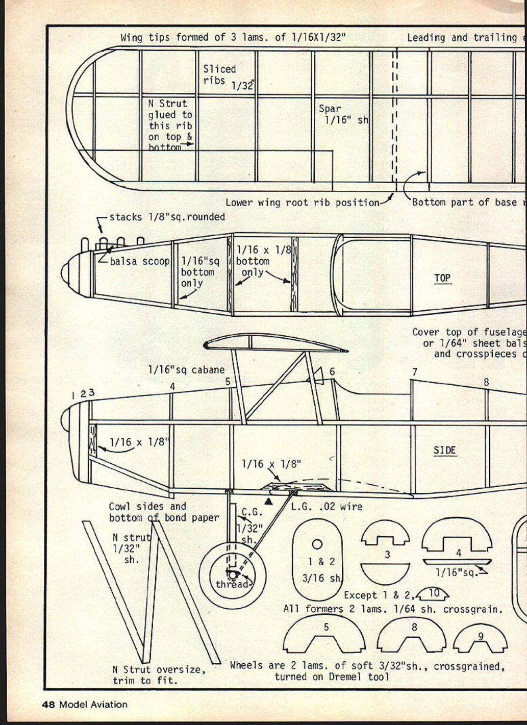
- Wing tips: formed of 3 laminations of 1/32" x 1/16" balsa.
- Leading and trailing edges: typical strip stock as per plans.
- Ribs: sliced from 1/32" sheet (dihedral break ribs in top wing have a 1/16" sq. balsa bottom piece).
- Spar: 1/16" (sheet or strip as shown on plans).
- Lower wing root ribs: 1/16" solid sheet at the base (root).
- Root base / stacks: 1/8" sq., rounded where required.
- Fuselage top cover: 1/64" sheet balsa (sanded down from 1/32" if desired), with crosspieces.
- Cabane: 1/16" sq. cabane posts.
- N strut: 1/32" sheet; cut oversize and trim to fit. Glue top and bottom to appropriate ribs.
- Landing gear wire: .02" music wire (each side bent from a single piece).
- Wheels: two laminations of soft 3/32" sheet balsa, cross-grained and turned on a Dremel tool.
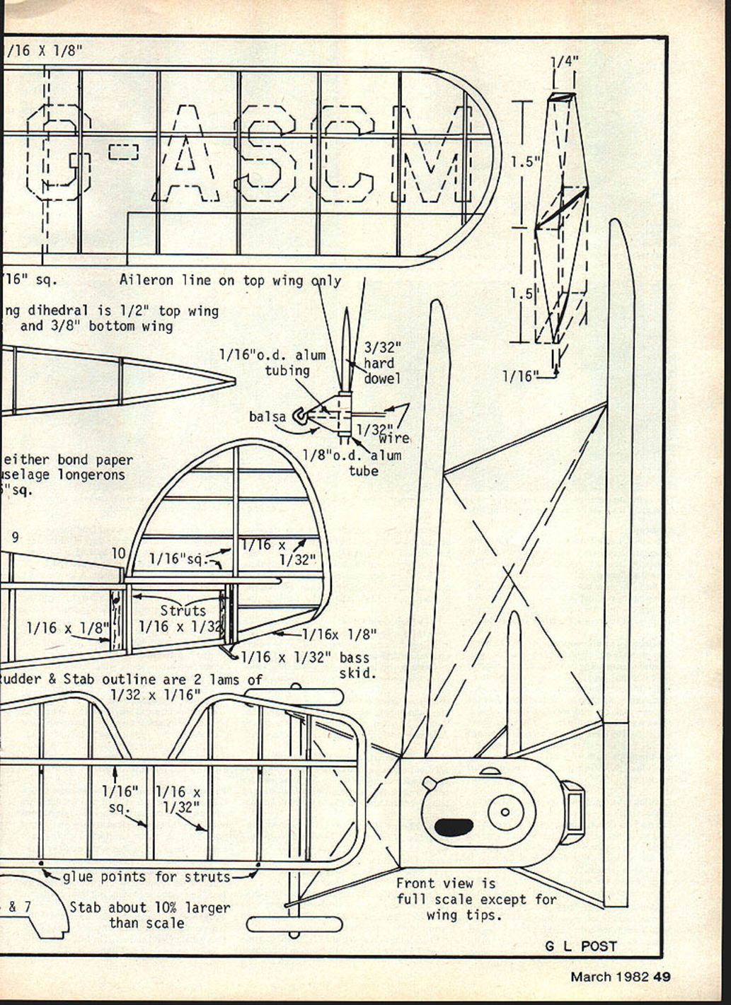
- Aileron control: aileron line on top wing only.
- Wing dihedral: original model used 1/2" at top wing tips, 3/8" at bottom wing tips (scale dihedral on the plans is probably adequate).
- Aluminum tubing: 1/16" o.d. and 1/8" o.d. used in prop/shaft assemblies.
- Dowels and shafts: 3/32" hard dowel, 1/32" wire for prop shaft/winding, etc.
- Longerons: 1/16" sq. balsa (or use bond paper construction as an alternative).
- Struts: 1/16" x 1/32" strips; other strut stock per plans.
- Skid: 1/16" x 1/32" balsa skid.
- Rudder & stabilizer outlines: two laminations of 1/16" x 1/32" balsa (cross-grained).
- Except for formers 1 & 2, all formers are two laminations of 1/64" sheet, cross-grained.
- Cowl sides and bottom: bond paper recommended for cowl.
- Stab: about 10% larger than scale on the model build described.
- Front view of fuselage: full scale except for wing tips.
The model described was built for outdoor flying and used rather large balsa. If an indoor model is desired, use smaller wood where feasible. The original model weighed 11 grams (including lead weight in the nose but excluding rubber). All outlines are scale except the stabilizer, which is about 10% larger than scale.
Fuselage
To ensure two identical sides, the side outline was traced onto thin cardboard and cut out; the two sides were built inside the cardboard cutout. This is easier for many builders than constructing one side over the other.
Cover the top of the fuselage (over the formers) with 1/64" sheet balsa, sanded thin from 1/32" if necessary. Bond paper can be used, but it tends to sag when tissued and doped and is heavier. The formers on the plans are shown full dimension; if using 1/64" covering, reduce the radii of the formers by that amount.
Landing gear
The landing gear is bent from two pieces of .02" music wire. Each side of the gear is a single piece with ends bent to provide the correct splay. Cut the ends to about 1/4" length, sharpen, and stick them through the bottom longeron into the 1/16" x 1/8" crosspieces. Use a pin to pre-make the holes in the fuselage sides. Insert the wire and "Hot Stuff" (cyanoacrylate) the joint; the glue hardens the balsa, making it very rugged.
The axle is sanded round from 3/32" square balsa. Hot Stuff it to the wire gear and wrap two or three loops of gray thread (to simulate shock cord) around the wire and over the axle; Hot Stuff and trim the thread ends. The wheels are held in place with shortened pins and Hot-Stuffed. Hubcaps are cut from rounded balsa and Hot-Stuffed onto the pin heads. The landing gear fairing is 1/32" sheet balsa Hot-Stuffed to the wire.
Wheels are made from two pieces of soft 3/32" sheet balsa, glued together cross-grained. Drill a 1/16" hole in the center and screw a 2-56 bolt through it. Chuck the bolt into a Dremel tool and shape the wheel using sandpaper and a shaping tool (a sharp pencil can work). When finished, insert a short piece of 1/32" I.D. aluminum tubing into the center hole and Hot-Stuff it. Assemble the gear after the fuselage has been tissue-covered.
Wings
Wing tips were made of three laminations of 1/32" x 1/16" balsa, soaked in water and shaped around a 1/16" balsa form. Wax the edge of the form to prevent sticking. Use thinned white glue for laminations.
Ribs are sliced from 1/32" sheet except for the dihedral break ribs in the top wing which have a 1/16" square balsa bottom piece. Base (root) ribs of the lower wings are 1/16" solid sheet and must be glued at the correct angle to produce the proper dihedral.
The original model had 1/2" dihedral in the upper wing tips and 3/8" in the lower wing tips. The scale dihedral shown on the plans for both wings would probably be adequate.
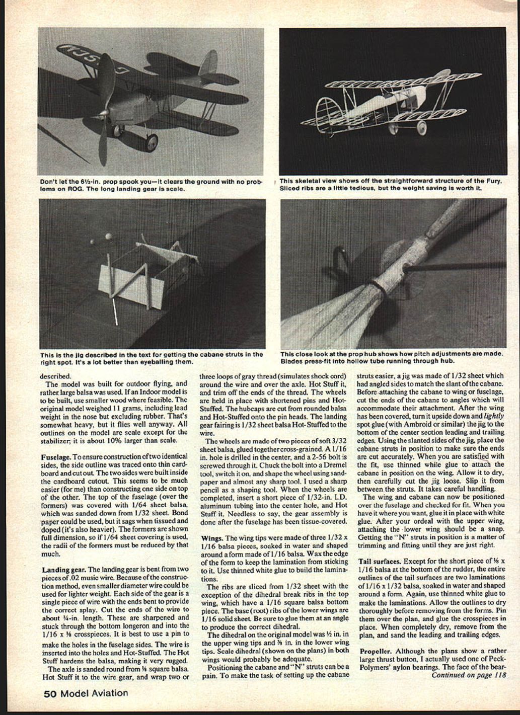
Positioning the cabane and N-struts can be tedious. To ease setup, make a jig of 1/32" sheet with angled sides matching the cabane slant. Before attaching the cabane to wing or fuselage, cut the cabane ends at the required angles. After the wing is covered, turn it upside down and spot-glue the jig to the bottom of the center section leading and trailing edges. Use the jig to check and trim the cabane ends for accurate fit. When satisfied, attach the cabane to the wing with thinned white glue, allow it to dry, then carefully cut and slip the jig away.
With the upper wing and cabane in place, position them over the fuselage and check fit. Glue in place with white glue. Attaching the lower wing is easier; fit the N-struts by trimming and adjusting until they are correct.
Tail surfaces
Except for a short piece of 1/16" x 1/16" balsa at the bottom of the rudder, the tail outlines are built from two laminations of 1/16" x 1/32" balsa, soaked and shaped around a form. Use thinned white glue for the laminations. Allow the outlines to dry thoroughly, then pin them over the plan and glue the crosspieces in place. When dry, remove from the plan and sand the leading and trailing edges.
Propeller
The plans show a rather large thrust button, but the builder used a Peck-Polymers nylon bearing, sanded down to about 1/32" thickness to place the spinner closer to the nose block for a more scale appearance.
The propeller was carved from 1/8" sheet balsa per the drawing on the plans. The prop (6-1/4" diameter on the original) is large but the airplane will take off without ground scraping; it takes off nose-up as most rubber models do. After carving the blades, the prop hub is built by making cutouts in the prop center and gluing in 1½" lengths of 3/32" hardwood dowel in each blade slot. Leave about 1/4" of dowel extending beyond each blade, trim and sand to blade thickness. Adjust blade shape and pitch as desired, or use a plastic prop if carving is not preferred.
Spinner construction: select a soft balsa block about 3/8" square and 3/4" long. Drill a 1/16" hole along the block center for the prop shaft. Drill a 1/32" hole intersecting near one end for a short piece of 3/32" I.D. aluminum tubing (the hub). Enlarge holes and align tubing so a 1/32" I.D. aluminum tube inserted through the spinner butts against the smaller back hole. Use a piece of 1/32" music wire through the shaft and hub tubing to ensure alignment, then Hot-Stuff the tubing in place. Cut a notch in the end of the shaft tubing to accept the 1/32" wire shaft winding loop.
Insert the prop hub dowels into the 3/32" hub tubing; fit them tight so blade pitch can be adjusted by test flying. On the original, at 1½" from the tip the blade was at about a 40° angle to the prop shaft. Blades need not be glued if the fit is snug. After the nose block is completed, assemble the nose unit and bend the wire hook. Use Teflon washers between the prop and thrust bearing.
The plans show a plug glued to the back of the nose block to hold it in place; shape it to fit the opening created by former and crosspieces at station #3.
Covering
The full-size aircraft was painted silver all over with white identification letters. The identification on the model plans is in scale positions (underside of left lower wing and top of upper right wing). The builder used gray tissue (heavier than ideal for a Peanut); experimenting with thinned paints or dyes to spray a gray onto white lightweight Japanese tissue is recommended.
After covering, spray the tissue with alcohol (use water only sparingly on small areas where wrinkles might develop). Then spray once or twice with thinned clear dope (about 30–40% dope, 60–70% thinner).
Lettering was cut from white moisture-adhesive-backed labels and affixed to the tissue. Exposed wood surfaces (prop, wheels, etc.) are painted with silver or gray dope.
Flying
This was the builder's second attempt at Peanut Scale. Balance the model at the point shown on the plans. A single loop of 1/32" x 3/32" rubber 10–12" long is a good starting point; use longer loops to find the correct power/duration/turns combination.
The original model required 1/32" left thrust and 1/32" positive incidence for the stab. Allow for possible incidence adjustments in the stab arrangement. Although auxiliary trim tabs on scale models are often frowned upon, the Fury legitimately had a trim tab on the left elevator (full-scale), about 3" x 7", because the full-size aircraft was tail-heavy — as was the model.
Scale documentation
Reprints of the original January 1956 Aero Modeller article on the Fury, including text, pictures, and a 1/48-scale drawing, and a larger 1/24-scale diazo print, are available from Model & Allied Publications, Ltd., in England, or from MAP agents in the U.S. The MAP Plan No. is 2786. Addresses:
- Model & Allied Publications Ltd. (Plan Sales), P.O. Box 35, Hemel Hempstead, Herts. HP1 1EE, England.
- Repla-Tech International, 48500 McKenzie Highway, Vida, OR 97488.
- Hobby Hideaway, RR 2, Box 19, Delavan, IL 61734.
- Bob Holman Plans, P.O. Box 741, San Bernardino, CA 92402.
Get after it, and enjoy a Peanut bipe at its best.
Transcribed from original scans by AI. Minor OCR errors may remain.

