
Italian Gem - the Fiat G-50
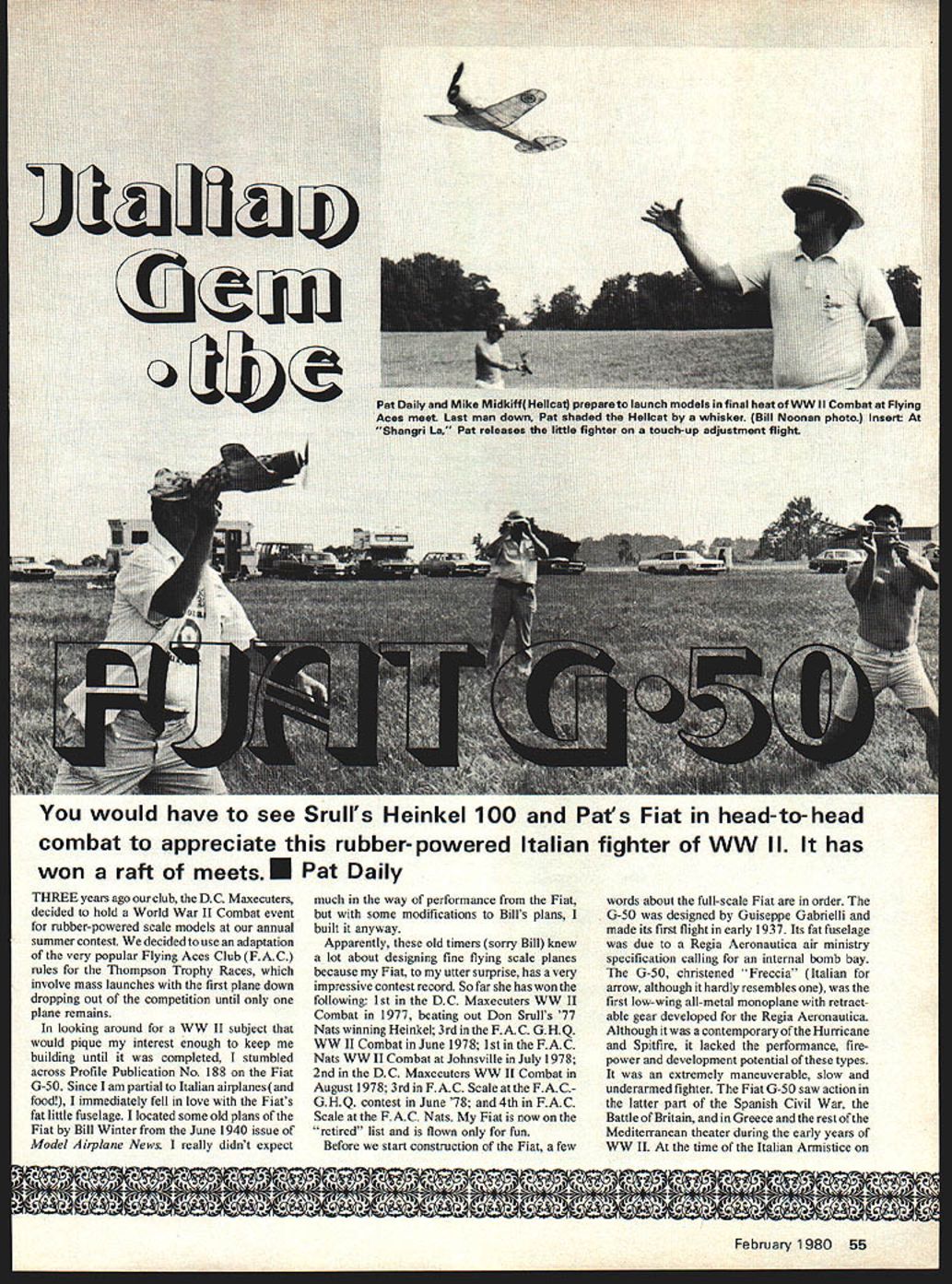
You would have to see Srull's Heinkel 100 and Pat's Fiat in head-to-head combat to appreciate this rubber-powered Italian fighter of WWII. It has won a raft of meets. — Pat Daily
Three years ago our club, the D.C. Maxecuters, decided to hold a World War II Combat event for rubber-powered scale models at our annual summer contest. We decided to use an adaptation of the very popular Flying Aces Club (F.A.C.) rules for the Thompson Trophy Races, which involve mass launches with the first plane down dropping out of the competition until only one plane remains.
In looking around for a WWII subject that would pique my interest enough to keep me building until it was completed, I stumbled across Profile Publication No. 188 on the Fiat G-50. Since I am partial to Italian airplanes (and food!), I immediately fell in love with the Fiat's fat little fuselage. I located some old plans of the Fiat by Bill Winter from the June 1940 issue of Model Airplane News. I really didn't expect much in the way of performance from the Fiat, but with some modifications to Bill's plans, I built it anyway.
Apparently, these old timers (sorry Bill) knew a lot about designing fine flying scale planes because my Fiat, to my utter surprise, has a very impressive contest record. So far she has won the following:
- 1st in the D.C. Maxecuters WWII Combat in 1977, beating out Don Srull's '77 Nats-winning Heinkel
- 3rd in the F.A.C. G.H.Q. WWII Combat in June 1978
- 1st in the F.A.C. Nats WWII Combat at Johnsville in July 1978
- 2nd in the D.C. Maxecuters WWII Combat in August 1978
- 3rd in F.A.C. Scale at the F.A.C. G.H.Q. contest in June 1978
- 4th in F.A.C. Scale at the F.A.C. Nats
My Fiat is now on the "retired" list and is flown only for fun.
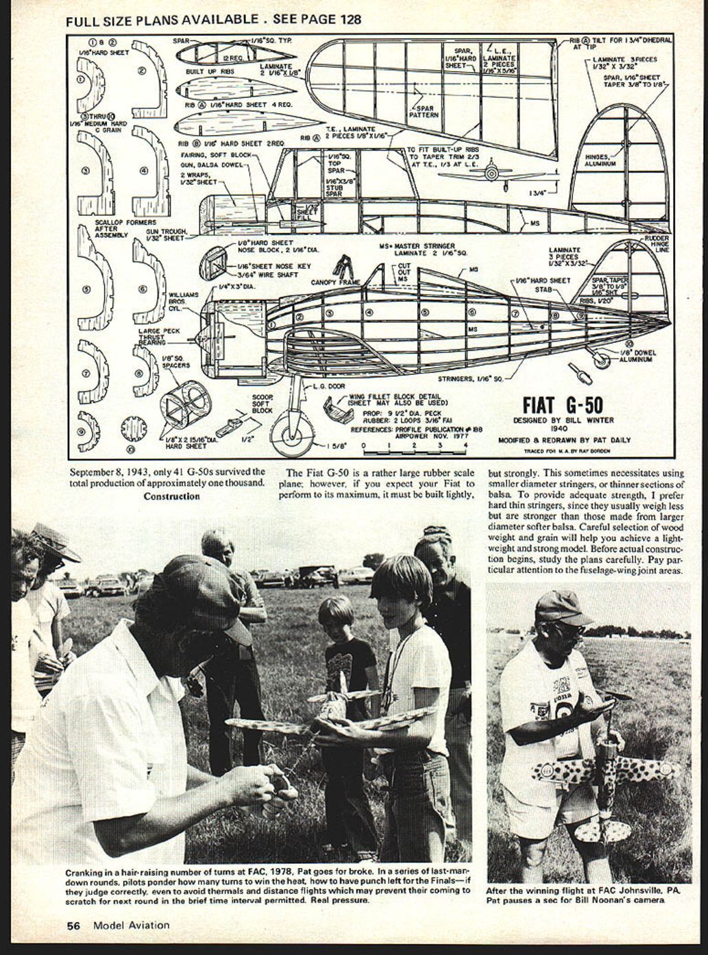
Before we start construction of the Fiat, a few words about the full-scale Fiat are in order. The G-50 was designed by Giuseppe Gabrielli and made its first flight in early 1937. Its fat fuselage was due to a Regia Aeronautica air ministry specification calling for an internal bomb bay. The G-50, christened "Freccia" (Italian for arrow, although it hardly resembles one), was the first low-wing all-metal monoplane with retractable gear developed for the Regia Aeronautica. Although it was a contemporary of the Hurricane and Spitfire, it lacked the performance, firepower and development potential of these types. It was an extremely maneuverable, slow and underarmed fighter. The Fiat G-50 saw action in the latter part of the Spanish Civil War, the Battle of Britain, and in Greece and the rest of the Mediterranean theater during the early years of WWII. At the time of the Italian Armistice on September 8, 1943, only 41 G-50s survived out of a total production of approximately one thousand.
Construction
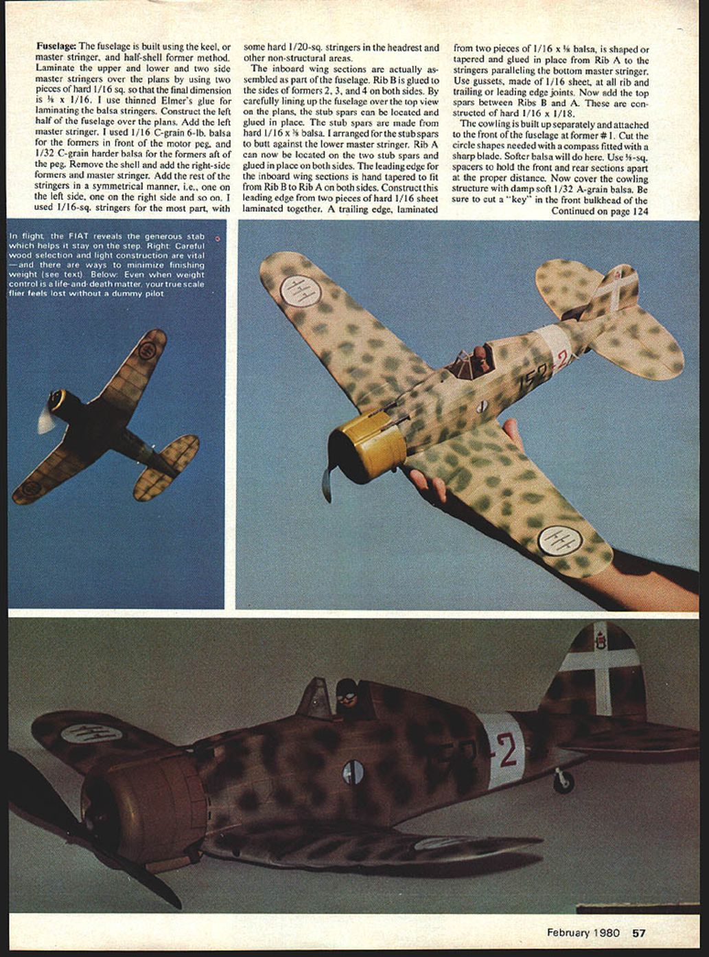
The Fiat G-50 is a rather large rubber scale plane; however, if you expect your Fiat to perform to its maximum, it must be built lightly but strongly. This sometimes necessitates using smaller diameter stringers, or thinner sections of balsa. To provide adequate strength, I prefer hard thin stringers, since they usually weigh less but are stronger than those made from larger-diameter softer balsa. Careful selection of wood weight and grain will help you achieve a lightweight and strong model. Before actual construction begins, study the plans carefully. Pay particular attention to the fuselage-wing joint areas.
Fuselage
The fuselage is built using the keel-master-stringer half-shell former method. Laminate the upper and lower master stringers over the plans using two pieces of hard 1/16" sq., final dimension 5/32 x 1/16. I use thinned Elmer's glue for laminating the balsa stringers.
Construct the left half of the fuselage over the plans and add the left master stringer. I used 1/16" C-grain 6-lb. balsa for the formers in front of the motor peg, and 1/32" C-grain harder balsa for the formers aft of the peg. Remove the shell and add the right-side formers and master stringer. Add the rest of the stringers symmetrically (one on the left, one on the right, etc.). I used 1/16" sq. stringers for the most part, with some hard 1/20" sq. stringers in the headrest and other non-structural areas.
The inboard wing sections are actually assembled as part of the fuselage. Rib B is glued to the sides of formers 2, 3, and 4 on both sides. By carefully lining up the fuselage over the top view on the plans, the stub spars can be located and glued in place. The stub spars are made from hard 1/16 x 3/32 balsa and are arranged to butt against the lower master stringer. Rib A can then be located on the two stub spars and glued in place on both sides.
The leading edge for the inboard wing sections is hand-tapered to fit from Rib B to Rib A on both sides. Construct this leading edge from two pieces of hard 1/16" sheet laminated together. A trailing edge, laminated from two pieces of 1/16 x 1/16 sheet, is shaped or tapered and glued in place from Rib A to the stringers paralleling the bottom master stringer. Use gussets of 1/16" sheet at all rib and trailing- or leading-edge joints. Add the top spars between Ribs B and A; these are constructed of hard 1/16 x 1/8.
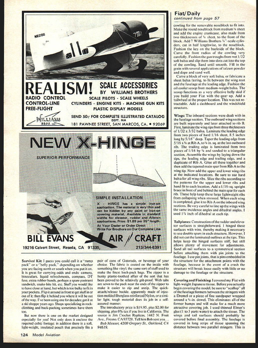
The cowling is built up separately and attached to the front of the fuselage at former #1. Cut the circular shapes with a compass fitted with a sharp blade; softer balsa will do here. Use 1/4" sq. spacers to hold the front and rear sections apart at the proper distance. Now cover the cowling structure with damp soft 1/32" A-grain balsa. Be sure to cut a "key" in the front bulkhead of the cowling for the removable noseblock to fit into. Make the round noseblock from medium 1/8" sheet and add the engine crankcase, also made from two thicknesses of 1/8" sheet, to the front of the block. Add 7 Williams Brothers 1/8"-scale cylinders, cut in half lengthwise, to the noseblock. Fashion the key on the backside of the block. Carve the front radius of the cowling very carefully. Fashion the gun troughs from wetted 1/32" soft balsa and slip them into slots cut into the top of the cowling. Sand until smooth. Fill in the grain with several applications of talcum powder and dope, then sand well.
Carve a block of very soft balsa, or fabricate a sheet balsa fairing, to fit between the wing root and the fuselage at the leading edge. Fashion the oil cooler scoop from medium-weight balsa. The scoop functions as a very effective belly skid if you build your Fiat with the gear up. Add a tailwheel at the proper location; this was not retractable on the full-scale aircraft. Add a dashboard and the windshield structure.
Wings
The inboard sections were dealt with in the fuselage section. The outboard wing sections are built separately and later attached to Rib B. First, laminate the wing tips from three thicknesses of 1/32 x 3/32 balsa. Laminate the leading edge from two pieces of hard 1/16" sheet, 8.5 inches long by 5/16" deep. Taper the leading edge from 5/16 x 3/16 at Rib A to 1/8" sq. at the last outboard rib. The trailing edge is laminated from two pieces of 1/16 x 3/16 and sanded to a triangular section.
Assemble the wings by laying down the tip, the leading edge, the trailing edge, and a duplicate of Rib A. Glue all these together and then add the tapered main spar from Rib A to the wing tip. Now add the upper and lower wing ribs at the indicated locations. Be sure to use hard balsa for all wing ribs. Slice the ribs according to the patterns for the upper and lower ribs and hand-fit to each location. Add a 1/16" sq. upright brace in front of and behind the main spar for each rib. These help keep the large lightweight ribs from collapsing when stressed.
When each wing is completed, glue it to Rib A in the inboard wing sections. Be very careful to line up the wings with the same incidence and dihedral angles. I used 1-1/2° of dihedral at each tip.
Tailplanes
Construction of the rudder and elevator surfaces is straightforward. I hinged these surfaces with wire, which makes it necessary to use double spars in each structure. I did not cut the laminated outlines at the tips; this helps keep the hinged surfaces stiff while still allowing plenty of movement for adjustments. Sand all tail surfaces to a symmetrical section before attaching them with pin joints to the fuselage. Use pin joints (pins embedded in the structure for the attachment points) because in the event of a crash the surface will break loose easily with little or no damage to the fuselage or the surface.
Covering and Finishing
I covered my Fiat with lightweight Japanese tissue. Before covering the model, be sure to "scallop" all of the fuselage formers between the stringers with a Dremel or a piece of fine sandpaper wrapped around a 1/4" dowel. This eliminates all former bumps and makes for a much more attractive covering job.
I used thinned Elmer's glue (3 parts glue to 1 part water) to attach the tissue. The wings and tail surfaces should probably be covered before final assembly. The fuselage is covered in long strips of tissue spanning the distance between the two parallel stringers: first apply a strip to the lower right side and the upper left side, then apply the remaining two strips to the other sides. After the covering is dry, seal the tissue with thinned dope. Sand lightly and apply the final color scheme. I used silver dope on the fuselage and black dope for the cowl and fin. Install the windshield and the dashboard after the dope is dry.
Add the balsa gun fairings and then water-shrink the entire covered plane. I like to "shrink in" my wing washout rather than build it in—I used about 1/8" of washout at each wing tip.
Dope the plane with two coats of thinned dope, preferably nitrate, to which you have added an appropriate amount of plasticizer. The cowl section, as mentioned before, is not covered but is filled in with several coats of dope and talcum powder followed by sanding. Take your time here because the cowl must look like metal rather than "grainy" balsa if you really want a nitty-looking Fiat.
After clear doping, select your favorite Fiat color scheme. I chose the sand-and-splinter effect with a yellow cowling and light gray undersurfaces. I used Floquil model railroad paints thinned with very thin nitrate dope and sprayed on with an airbrush. After adding all the colors, details such as panel lines can be added with a soft gray pencil and "fixed" with a coat of clear nitrate sprayed on.
My Fiat was built with the gear "up." I simulated the gear doors and wheels with balsa and paper glued in place with rubber cement. The nosegear was cut from either black or red tissue and doped on. Next, add a pilot carved from foam and machine guns made from balsa or aluminum tube stock.
Rigging
The Fiat features flying wires and landing wires. The flying wires are 1/16" piano wire and are arranged as on the full-scale aircraft. Use small brass elbows in the cabane and on the lower wing attachment points. The landing wires are 3/32" piano wire bent to fit. Make small wire turnbuckles from 1/32" music wire in the usual manner to provide tensioning.
Power and Flying (Rubber Motor)
My Fiat uses a single 5/8 oz. loop of 1/8" rubber about 8 feet long for most contest flying. For calm conditions you can use heavier rubber, but remember the Fiat must be built lightly to perform to its maximum. Cranking hair-raising numbers of turns into the motor can be exciting. In rounds where many down rounds occur, pilots ponder how many turns to give so they will have punch left for later rounds. Finals, if judged correctly, avoid thermals. Distance flights may prevent coming in on the scratch line during the brief time interval permitted.
I use 4 strands (2 loops) of FAI 3/16" rubber for some flights. The total length of rubber I have used is about 15–17 feet. Tie the rubber with a good knot, lube it with Dow 33 or Sig Rubber Lube, and proceed to "braid" the motor. Do this by having your buddy hold the knotted end while you put in about 17 winder turns with a 16:1 winder. Then grab the knotted end from your buddy while still holding the other end and place both ends over your index finger. Pull out the now 4-stranded motor several times until it looks nicely braided.
I used a 9-1/4" Peck-Polymers plastic prop and a large Peck-Polymers bearing with 5° of down thrust. The finished weight of my Fiat without rubber was about 70 grams (slightly over 2 oz.) and about 95 grams with rubber. Tie the motor, install it, and test-glide the plane over tall grass. When the glide is reasonable, try a few winds and launch the plane slightly nose down. If everything is still OK, try about 30 winder turns.
My Fiat flies in a large left circle with a left glide. When properly trimmed, it will fly in a slightly nose-up attitude and glide very well with the braided motor. I fly for fun with about 100 winder turns (1600 total turns) and get 45 seconds or more duration. I go for broke with 130-plus turns—except you can't get that many turns in with a 16:1 winder because the motor is too strong. My plane flew for 1:53 to beat Mike Midkiff's super Hellcat at the F.A.C. Nats and I needed to use a 5:1 winder to get over 2000 total turns in it.
Trimming and Final Assembly
Assemble the complete model and move the pylon until the ship balances where indicated on the plans, or very slightly forward, then epoxy in place. Don't be in too much of a hurry to get out to the flying field. Assemble the model and check thoroughly for proper balance and the correct warps. The CG should be where shown on the plans. If it balances tail-heavy, move the engine (or noseblock) forward by inserting additional plywood spacers between the firewall and the engine mount. The engine should point straight ahead, or slightly left.
Hand-glide the model to be sure there's no stalling or diving tendency. Correct by shimming the front or back of the stab with pieces of thin ply. There should be a definite glide circle. For rubber-powered models, run motor tests on the winder to familiarize yourself with how the motor behaves and to make sure everything is secure.
For initial powered test flights (or long motor runs), make adjustments in small increments. If the model tends to loop on short runs, remove incidence; if it has a shallow climb angle or the nose tucks under, add incidence by shimming the rear of the stab with thin wood. If the model tends to go left on longer motor runs, add right rudder tab using pieces of 1/16 x 1/8 balsa cut to a trailing-edge section and glued to the rudder or elevator trailing edge as required.
Transcribed from original scans by AI. Minor OCR errors may remain.

