
IT'S ABOUT TIME!
A toy that can be bought at a discount store for two bucks can be changed into a dethermalizer (DT) timer for HL gliders and other small free-flight models. It weighs less than two grams. Here are complete details on how to make the modification, with advice on installing the finished timer.
Don Lindley and Stan Stoy
A mechanical dethermalizer timer that weighs less than two grams and will time accurately for over 10 minutes? Not likely, you say. Well, the timer pictured in this article weighs 1.85 grams and is repeatable within four seconds at the two-minute level. At 10 minutes it is repeatable within 20 seconds. The size is very compact: 7/32 x 17/32 x 1-1/16 in. Finally, note that it can be constructed in less than an hour from a toy that costs less than $2. In fact, we recently built four in less than two hours.
The development of this gadget is the result of the work of many people who selflessly shared their ideas through various newsletters and publications. Two of those people deserve special mention. The first is Jim Lewis who, back in 1977, made use of the clockwork mechanism from a Mini Bathtub toy to actuate the tail surfaces on a hand-launched glider. Publication of this in Bill Mathews' FF Flier started many people thinking. However, it wasn't until 1980 that Dr. Edmond Liem of the A-2 Glider team from Holland solved the problem of slowing the timer down from a maximum run of 20 seconds to over two minutes. He did this by increasing the moment of inertia of the mechanism's pawl by embedding a ball-headed pin in the pawl. The authors played around with this simple, effective device for some time, but were dissatisfied with the space required for the pin to swing outside the gear case and the more-than-three-gram weight of the device.
Finally, it became apparent that the rubber band which held the DT down was more than adequate to drive the timer without the spring originally used to drive the toy. Within several months the authors (living in areas about 300 miles apart) had produced practically identical devices without corresponding. This usually indicates some sort of optimization.
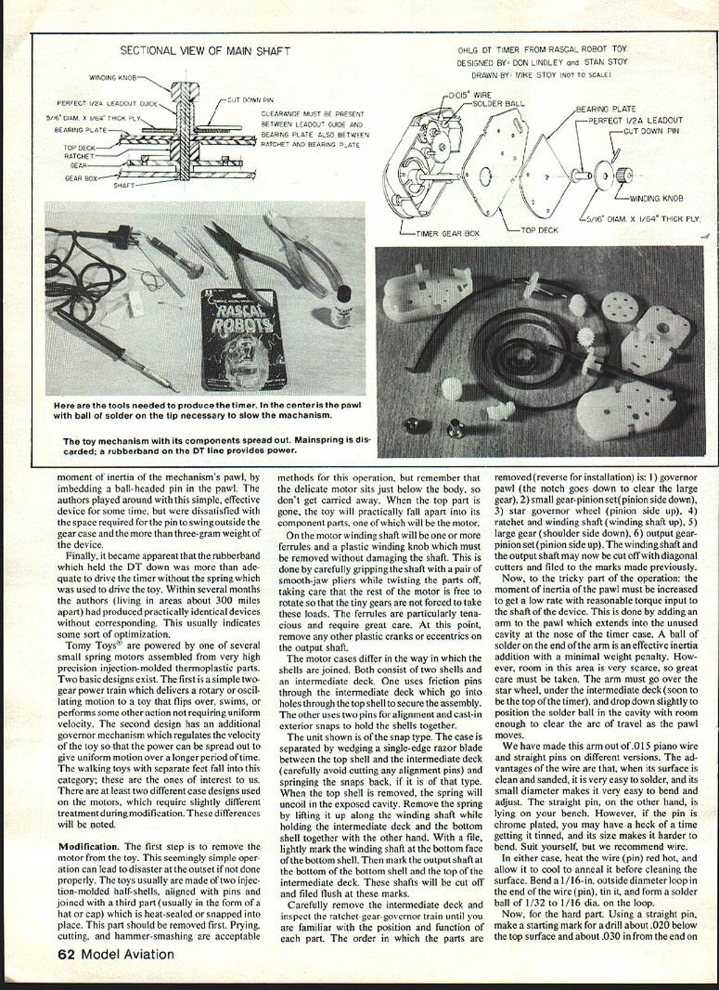
Tomy toys are powered by one of several small spring motors assembled from very high-precision injection-molded thermoplastic parts. Two basic designs exist. The first is a simple two-gear power train which delivers a rotary or oscillating motion to a toy that flips over, swims, or performs some other action not requiring uniform velocity. The second design has an additional governor mechanism which regulates velocity so the power can be spread out to give uniform motion over a longer period. The walking toys with separate feet fall into this category; these are the ones of interest to us. There are at least two different case designs used on the motors, which require slightly different treatment during modification. These differences will be noted.
Modification
The first step is to remove the motor from the toy. This seemingly simple operation can lead to disaster at the outset if not done properly. The toys usually are made of two injection-molded half-shells, aligned with pins and joined with a third part (usually in the form of a hat or cap) which is heat-sealed or snapped into place. This part should be removed first. Prying, cutting, and hammer-smashing are acceptable methods for this operation, but remember that the delicate motor sits just below the body, so don't get carried away. When the top part is gone, the toy will practically fall apart into its component parts, one of which will be the motor.
On the motor winding shaft will be one or more ferrules and a plastic winding knob which must be removed without damaging the shaft. This is done by carefully gripping the shaft with a pair of smooth-jaw pliers while twisting the parts off, taking care that the rest of the motor is free to rotate so the tiny gears are not forced to take these loads. The ferrules are particularly tenacious and require great care. At this point remove any other plastic cranks or eccentrics on the output shaft.
The motor cases differ in the way the shells are joined. Both consist of two shells and an intermediate deck. One uses friction pins through the intermediate deck which go into holes through the top shell to secure the assembly. The other uses two pins for alignment and cast-in exterior snaps to hold the shells together.
The unit shown is of the snap type. The case is separated by wedging a single-edge razor blade between the top shell and the intermediate deck (carefully avoid cutting any alignment pins) and prying the snaps back, if it is of that type. When the top shell is removed, the spring will uncoil in the exposed cavity. Remove the spring by lifting it up along the winding shaft while holding the intermediate deck and the bottom shell together with the other hand. With a file, lightly mark the winding shaft at the bottom face of the bottom shell. Then mark the output shaft at the bottom of the bottom shell and the top of the intermediate deck. These shafts will be cut off and filed flush at these marks.
Carefully remove the intermediate deck and inspect the ratchet-gear-governor train until you are familiar with the position and function of each part. The order in which the parts are removed (reverse for installation) is:
- governor pawl (the notch goes down to clear the large gear),
- small gear–pinion set (pinion side down),
- star governor wheel (pinion side up),
- ratchet and winding shaft (winding shaft up),
- large gear (shoulder side down),
- output gear–pinion set (pinion side up).
The winding shaft and the output shaft may now be cut off with diagonal cutters and filed to the marks made previously.
Now, to the tricky part of the operation: the moment of inertia of the pawl must be increased to get a low rate with reasonable torque input to the shaft of the device. This is done by adding an arm to the pawl which extends into the unused cavity at the nose of the timer case. A ball of solder on the end of the arm is an effective inertia addition with a minimal weight penalty. However, room in this area is very scarce, so great care must be taken. The arm must go over the star wheel, under the intermediate deck (soon to be the top of the timer), and drop down slightly to position the solder ball in the cavity with enough room to clear the arc of travel as the pawl moves.
We have made this arm out of .015 in. piano wire and straight pins on different versions. The advantage of the wire is that when its surface is clean and sanded, it is very easy to solder, and its small diameter makes it very easy to bend and adjust. The straight pin, on the other hand, is lying on your bench. However, if the pin is chrome plated, you may have a heck of a time getting it tinned, and its size makes it harder to bend. Suit yourself, but we recommend wire. In either case, heat the wire (or pin) red hot and allow it to cool to anneal before cleaning it and soldering. Bend a 1/16 in. outside-diameter loop at the end of the wire (pin), cut it, and form a solder ball of 1/32 to 1/16 in. diameter on the loop.
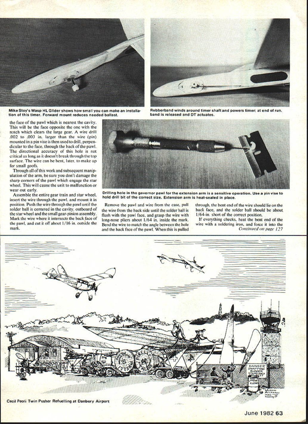
Using a straight pin, make a starting mark for a drill about .020 in. below the top surface and about .030 in. from the end on the face of the pawl which is nearest the cavity. This will be the face opposite the one with the notch which clears the large gear. A wire drill .002 to .003 in. larger than the wire (pin), mounted in a pin vise, is then used to drill, perpendicular to the face, through the back of the pawl. The directional accuracy of this hole is not critical as long as it doesn't break through the top surface. The wire can be bent later to make up for small goofs.
Through all of this work and subsequent manipulation of the arm, be sure you don't damage the sharp corners of the pawl which engage the star wheel. This will cause the unit to malfunction or wear out early.
Assemble the entire gear train and star wheel, insert the wire through the pawl, and mount it in position. Push the wire through the pawl until the solder ball is centered in the cavity, outboard of the star wheel and the small gear–pinion assembly. Mark the wire where it intersects the back face of the pawl, and cut it off about 1/16 in. outside the mark.
Remove the pawl and wire from the case, pull the wire from the back side until the solder ball is flush with the pawl face, and grasp the wire with long-nose pliers about 1/64 in. inside the mark. Bend the wire to match the angle between the hole and the back face of the pawl. When this is pulled through, the bent end of the wire should lie on the back face, and the solder ball should be about 1/64 in. short of the correct position.
If everything checks, heat the bent end of the wire with a soldering iron, and force it into the pawl. Keep the heat on the wire as you bury it in the plastic and a neat, strong mechanical joint will result. Check the clearance of the arm over the star wheel and the ball in the cavity. Bend as required.
The only remaining operation on the gear train is the removal of the two ears on the winding ratchet which retained the spring. These are cut off flush with the bottom of the slot through which the winding shaft runs, using the slot bottom as a guide.
Carefully reassemble the gear train, and slip the intermediate deck in place to hold everything in position. The only problem now is that the bearing hole through which the winding shaft runs has too much slop. To solve this problem, we use part of the original top plate as a bearing.
If the original case was of the snap-retained design, drill through the alignment pin holes in the top shell with a #61 (.039 in.) drill. Cut away the skirt around the top shell, leaving only the 1/32 in. thick top. Score the top with a razor about 1/16 in. beyond the winding shaft hole. Break it off on the scored line. Cut off all projections on the intermediate deck which are associated with retention of the power spring. Leave those parts on the bottom of the deck which serve to align the deck with the bottom shell.
Reassemble the intermediate deck with the bottom shell and gear train, taking one last look to be sure that everything is positioned properly. This should be your last look in here, so be sure that all the chips and shavings are gone.
Slip the short piece of the original top shell (which you have cut down to a coupon-shaped slab) over the winding shaft, and line it up with the alignment pins. Push it down flush with the intermediate deck. Hand-twist the winding shaft while holding the case closed, and make sure everything runs smoothly. If your fingers aren't interfering with the pawl or squeezing too tight, the unit should buzz away, offering good resistance to high torque because of the increased inertia of the pawl.
Check the winding shaft to make sure it has about .100 in. end play in the housing. This is critical. If the end play does not exist, add paper shims between the deck and the bearing plate until the proper play is achieved.
If everything looks right, cut off the alignment pins and/or snaps flush with the top surface, and weld the remaining hubs to the deck with a minimum of solder. Check the unit again. If you have to go back in at this point, you can carefully cut the welds at the snap clips and pop the parts at the alignment pins by wedging a razor in the slot, but this is your last chance. Get it right this time. If everything is OK, use the iron to tack-weld the intermediate deck to the bottom shell and the bearing plate to complete the timing assembly. The bearing plate must be welded around its whole outside edge. This piece takes the entire force of the rubber band.
Cut a 5/16 in. diameter disc of 1/64 in. plywood, and drill a 3/32 in. hole in the middle of it. Insert a Perfect 1/4A control-line leadout eyelet in the 3/32 in. hole, and cement its flange to the plywood with one of the high-viscosity cyanoacrylates or five-minute epoxy. Cut a straight pin point to a length that will project about 1/32 in. over the edge of the disc in a radial orientation and cement it. This acts as a DT release.
Clean and roughen the winding shaft with a piece of sandpaper (or a needle file) and slip the disc assembly on it with a .005 to .010 in. shim (the single-edge razor blade works) between the flange of the eyelet and the top of the timer. Cement the eyelet to the shaft, being sure you don't let cement run down into the bearings (this is why we use high-viscosity cement).
Push the original plastic winding knob down the shaft until it bottoms on the end of the eyelet. Cut off the protruding shaft, and file flush with the top of the winding knob. Remove the shim. This completes the timer.
The timer is powered by a rubber band (remember, we removed the spring). Typically, a rubber band made from a 1/8 in. loop of .030–.050 in. Indo-rubber is hooked over the projecting end of the straight pin on the disc of the timer with the rubber stretched to about twice its normal length in this position. The string to the DT is fastened to the other end of the rubber band.
The rubber is wound around the shaft of the eyelet by twisting the winding knob and allowing the rubber to climb the shaft. The time is determined by the number of turns and the nature of the rubber band used. The reason for the disc is that, while very little torque is required to run the timer, a lot is needed to get a clean release from the pin. Therefore, the last half-turn of the timer is made to run at a higher rate with more torque to get the clean release.
The life expectancy of the timer is not really known at this point. A prototype has been run for over 100 cycles at room temperature in clean conditions with no apparent wear or timing change. The timers were used at the Texas Nats with no temperature problems. They certainly will be at least as sensitive to dust and dirt as a Seelig or a Tatone, so don't use lubricants and seal them well. If the timer, without any protection, is mounted in a pocket in the airplane, be sure to seal the interior so that balsa dust doesn't find its way into the gears. Scotch Magic Tape can be used to cover the outside face of the timer, but a piece of typing paper should be cut to fit over the part which covers the ends of the shafts, so that the tape won't get into the bearings. We are now making vacuum-formed cups in which to mount the timers.
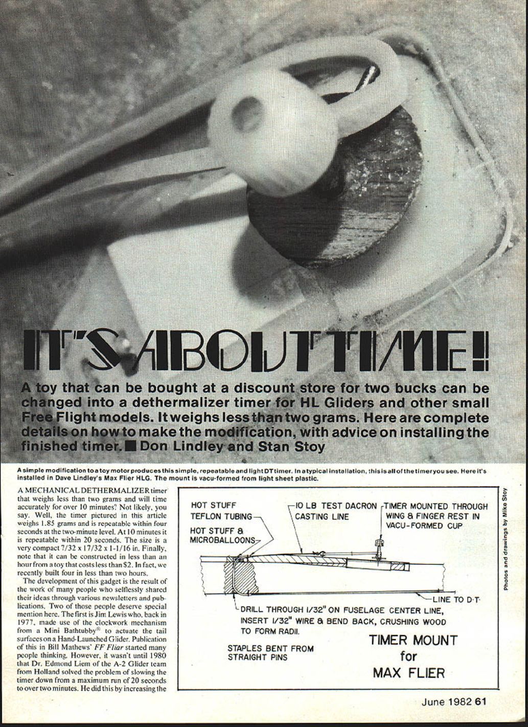
The photos show the timer mounted in the nose of Mike Stoy's Wasp (MA plan No. 343). Don Lindley prefers to mount the timer in the wing, using the finger-rest fairing to get the necessary depth, as shown in the picture of his Max Flier. In any case, you have a number of choices with this timer.
We do not consider this gadget to be a perfected, finished product. It is simply a reasonable step in the development program and is, therefore, worth noting. It is hoped that others will pick up on this and go ahead with other improvements in mechanics and techniques to make the item more useful.
Transcribed from original scans by AI. Minor OCR errors may remain.

