
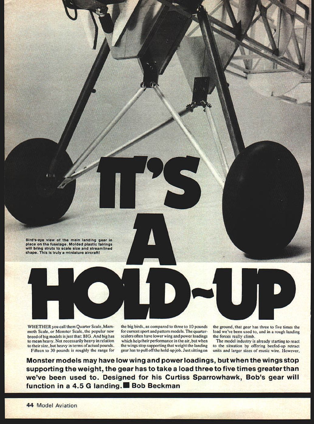
It's a Hold-Up
Big models: weight and landing-gear demands
Whether you call them quarter scale, mammoth scale, or monster scale, the popular new breed of big models is just that: big. And big has to mean heavy—not necessarily heavy in relation to their size, but heavy in actual pounds. Fifteen to 30 pounds is roughly the range for the big birds, as compared to three to 10 pounds for current sport and pattern models. The quarter-scalers often have lower wing and power loadings which help their performance in the air, but when the wings stop supporting that weight the landing gear has to pull off the hold-up job.
Just sitting on the ground, that gear has three to five times the load we've been used to, and in a rough landing the forces really climb. The model industry is already starting to react to the situation by offering beefed-up retract units and larger sizes of music wire. Quarter-scale builders are finding that the answers to our problems more often lie in scaling down full-size practice than in scaling up modeling methods. This can be particularly true with landing gear.
Designed for his Curtiss Sparrowhawk, Bob Beckman's gear will function in a 4.5 G landing.
Applying full-size practice to a 1/4-scale Curtiss Sparrowhawk
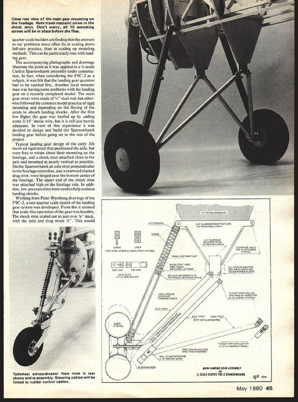
Working from Peter Westburg drawings of the F9C-2, a one-quarter-scale sketch of the landing gear system was developed. Typical landing-gear design of the early 1930s involved rigid struts that positioned the axle but were free to rotate about their fuselage mounting, and a shock strut attached close to the axle and mounted as nearly vertical as possible.
On the Sparrowhawk, an axle strut perpendicular to the fuselage centerline and a rearward-slanted drag strut are hinged near the bottom center of the fuselage. The upper end of the shock strut is attached high on the fuselage side. In addition, low-pressure tires are used to help cushion landing shocks.
From the scale sketch it seemed scale-like operation of the gear was feasible. The shock strut scaled out to just over 5/16" thick, with the axle and drag struts 3/16". This would allow the shock strut to operate in a scale-like manner.
Design and construction
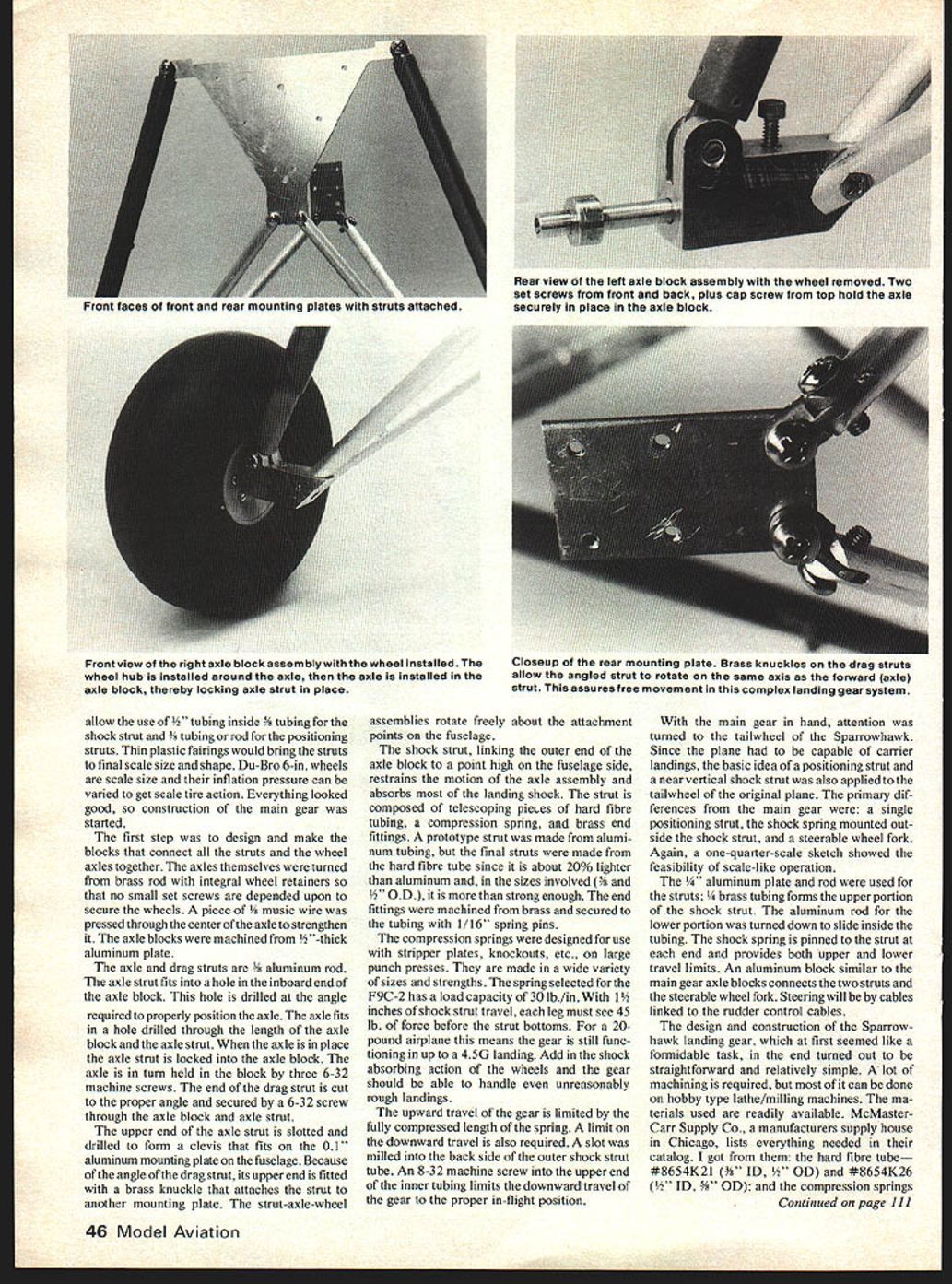
#### Axle blocks and wheel assemblies Construction of the main gear began with blocks to connect the struts and wheel axles. The axles themselves were turned from brass rod with integral wheel retainers—no small set screws were used; the wheels depend on a secure fit. A piece of C-wire was pressed through the center of the axle to strengthen it.
The axle blocks were machined from 3/8"-thick aluminum plate. The axle drag struts were 3/8" aluminum rod. The axle strut fits a hole in the inboard end of the axle block; the hole was drilled at the angle required to properly position the axle. The axle fits a hole drilled through the length of the axle block. With the axle strut in place the axle block is locked; the axle, when turned, is held to the block by three 6-32 machine screws. The end of the drag strut was cut to the proper angle and secured with a 6-32 screw.
Thin plastic fairings were used to bring the struts to final scale size and shape. Du-Bro 6 in. wheels were used; scale-size inflation pressure can be varied to get scale tire action.
The upper end of the axle strut is slotted and drilled to form a clevis that fits on the 0.1" aluminum mounting plate on the fuselage. Because of the angle of the drag strut, its upper end is fitted with a brass knuckle that attaches the strut to another mounting plate. The strut-axle-wheel assemblies rotate freely about the attachment points on the fuselage.
#### Shock strut The shock strut links the outer end of the axle block to a point high on the fuselage side, restraining the motion of the axle assembly and absorbing most of the landing shock. The strut is composed of telescoping pieces of hard fibre tubing, a compression spring, and brass end fittings.
A prototype strut was made from aluminum tubing, but the final struts were made from hard fibre tube since it is about 20% lighter than aluminum and, in the sizes involved (3/8" and 1/2" O.D.), more than strong enough. The end fittings were machined from brass and secured to the tubing with 1/16" spring pins.
The compression springs used are the type designed for stripper plates, knockouts, etc., on large punch presses and are made in a wide variety of sizes and strengths. The spring selected for the F9C-2 has a load capacity of 30 lb./in. With 1-1/2 inches of shock-strut travel, each leg must see 45 lb. of force before the strut bottoms. For a 20-pound airplane this means the gear is still functioning in up to a 4.5G landing. Add in the shock-absorbing action of the wheels and the gear should be able to handle even unreasonably rough landings.
#### Travel limits The upward travel of the gear is limited by the fully compressed length of the spring. A limit on the downward travel is also required. A slot was milled into the back side of the outer shock-strut tube. An 8-32 machine screw into the outer end of the inner tubing limits the downward travel of the gear to the proper in-flight position.
Tailwheel
Since the Sparrowhawk had to be capable of carrier landings, the basic idea of a positioning strut and a near-vertical shock strut was applied to the tailwheel of the model. The primary differences from the main gear were: a single positioning strut, the shock spring mounted outside the shock strut, and a steerable wheel fork.
The 1/4" aluminum plate and rod were used for the struts; 1/8" brass tubing forms the upper portion of the shock strut. The aluminum rod for the lower portion was turned down to slide inside the tubing. The shock spring is pinned to the strut at each end and provides both upper and lower travel limits. An aluminum block similar to the main gear axle blocks connects the two struts and the steerable wheel fork. Steering will be by cables linked to the rudder control cables.
Materials and sources
- Hard fibre tube: McMaster-Carr #8645K21 (3/8" ID, 1/2" OD) and #8645K26 (1/2" ID, 5/8" OD)
- Compression spring for the main gear: McMaster-Carr #9620K12
- Aluminum blocks and brass end fittings: machine-shop scraps (or machine from stock)
- Aluminum rod: 1/4" (1/4" rod is available in hardware stores; the author turned 3/8" rod down to 1/4")
- Brass tubing: 1/8" (available in hobby shops)
- Tailwheel shock spring: hardware store
- Wheels: Du-Bro 6 in.
Most machining can be done on hobby-type lathes and milling machines. McMaster-Carr and similar suppliers list the hard fibre tubing and springs in their hardware sections.
Conclusion and applicability
The design and construction of the Sparrowhawk landing gear, which at first seemed like a formidable task, turned out to be straightforward and relatively simple. A lot of machining was required, but the materials and parts are available. Although the gear described here was designed for the Curtiss F9C-2 Sparrowhawk in 1/4 scale, the basic methods are applicable to any reasonably large subject. You're not restricted to fixed-gear aircraft—quarter-scale retracts and other arrangements can also benefit from scale-like shock-absorbing designs. In my mind's eye I keep getting glimpses of a 1/4-scale Grumman F3F-3 with the wheels slowly pulling up into the fuselage sides.
Transcribed from original scans by AI. Minor OCR errors may remain.

