
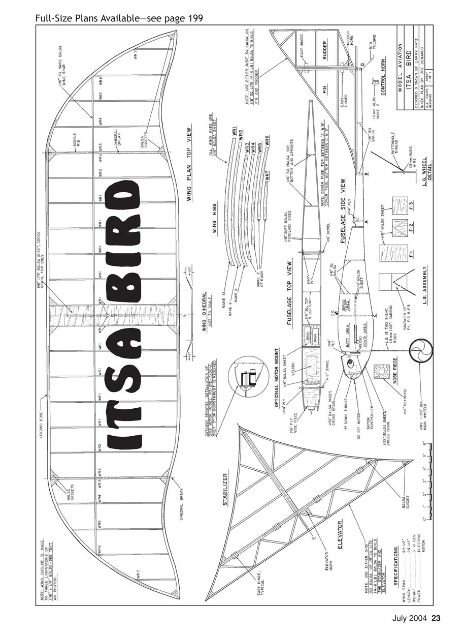
ITSA BIRD
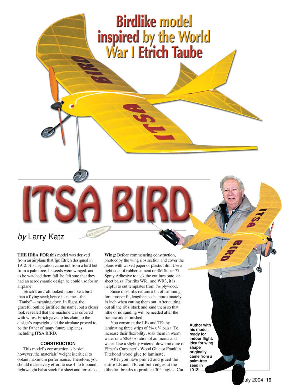
Birdlike model inspired by the World War I Etrich Taube
by Larry Katz
The idea for this model was derived from an airplane that Igo Etrich designed in 1912. His inspiration came not from a bird but from a palm tree. Its seeds were winged, and as he watched them fall, he felt sure that they had an aerodynamic design he could use for an airplane.
Etrich’s aircraft looked more like a bird than a flying seed; hence its name—the “Taube,” meaning dove. In flight, the graceful outline justified the name, but a closer look revealed that the machine was covered with wires. Etrich gave up his claim to the design’s copyright, and the airplane proved to be the father of many future airplanes, including ITSA BIRD.
CONSTRUCTION
This model’s construction is basic; however, the materials’ weight is critical to obtain maximum performance. Therefore, you should make every effort to use 4- to 6-pound lightweight balsa stock for sheet and for sticks.
Wing
Before commencing construction, photocopy the wing ribs section and cover the plans with waxed paper or plastic film. Use a light coat of rubber cement or 3M Super 77 spray adhesive to tack the outlines onto 1/16-inch sheet balsa. For ribs WR1 and WR3, it is helpful to cut templates from 1/16-inch plywood.
Since most ribs require a bit of trimming for a proper fit, lengthen each approximately 1/4 inch when cutting them out. After cutting out all the ribs, stack and sand them so that little or no sanding will be needed after the framework is finished.
Construct the leading edges (LEs) and trailing edges (TEs) by laminating three strips of 1/16 x 1/4-inch balsa. To increase their flexibility, soak them in warm water or a 50/50 solution of ammonia and water. Use a slightly watered-down mixture of Elmer’s Carpenter’s Wood Glue or Franklin Titebond wood glue to laminate.
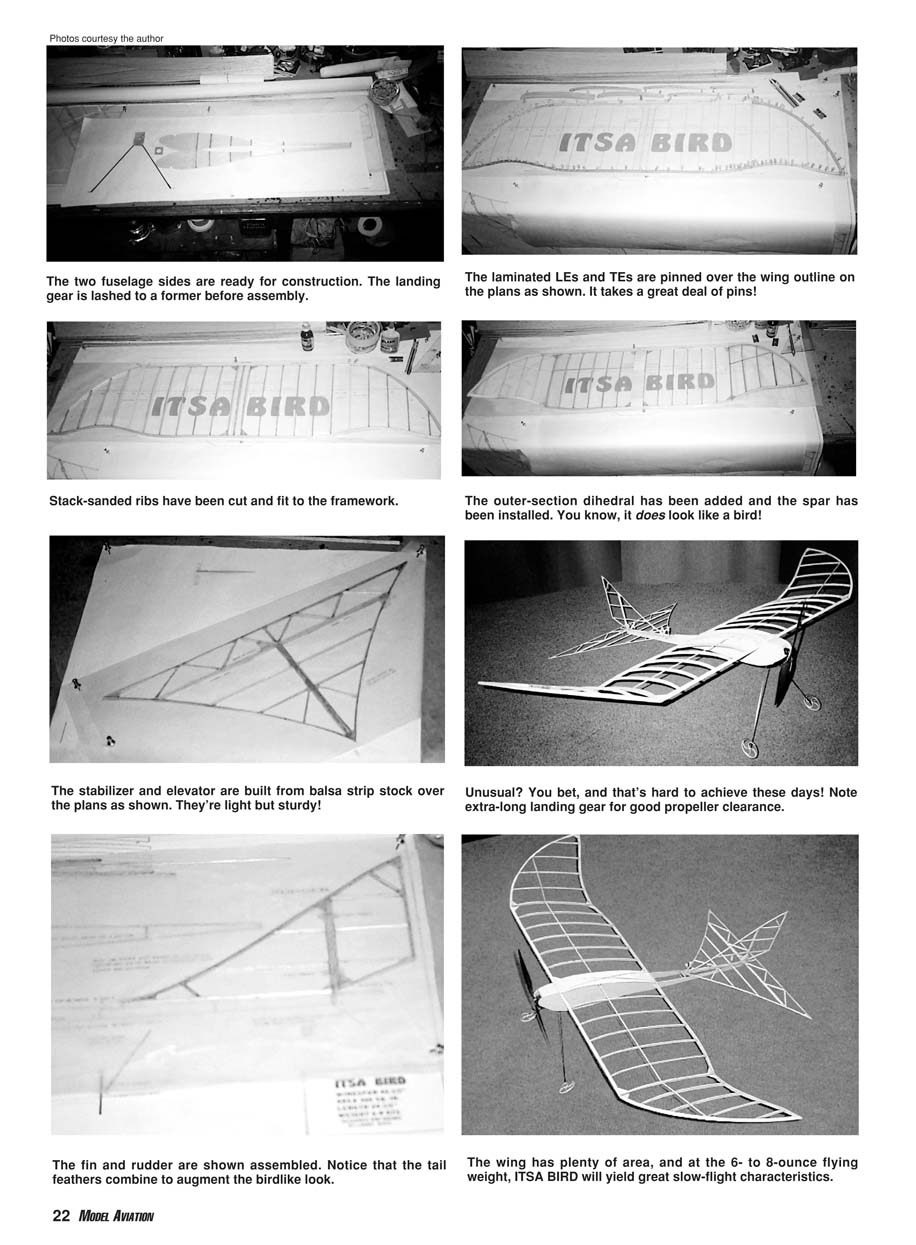
After you have pinned and glued the entire LE and TE, cut both edges at the dihedral breaks to produce 30° angles. Cut and glue each rib in place. Omit the double ribs WR3 until the dihedral is set. Leave the center-section pinned to the plans, and raise each wingtip 4 1/2 inches and glue in place. At this time you can install ribs WR3 and all wing gussets. Before removing the structure from the plans, install the 1/16-inch square spar and sheet the center-section (top only). When the wing is dry, remove it from the plans and round it by trimming, shaping, and sanding the entire LE and TE. Set aside for covering.
Tail Feathers
Elevator and rudder construction are basic. Either 3/32- or 1/8-inch square balsa will produce structures with little or no weight difference, as long as it is lightweight. The plans indicate the use of Sig Easy Hinges, but any comparable hinge is satisfactory.
I used thin sheet aluminum to form rudder and elevator horns. A good source for this material is the top of certain packaged products; I obtained my aluminum from a can of French’s French Fried Onions. You can also make horns from 1/32-inch plywood. Before you install the horns, sand the rudder and elevator.
Fuselage
Before you begin fuselage construction, cut the motor-mount nosepiece from 1/16-inch plywood and cut a hole large enough to accept whatever motor you intend to use. I also advise you to construct the landing-gear assembly at this time. This step requires you to cut formers F1, F2, F3, and two lengths of 1.5 mm carbon rod. Exercise caution when cutting carbon; it is best to place masking tape at the point of cut, and use a Dremel or similar tool.
Cut and bend 0.1 mm piano wire for the wheel axles, tie it to the rods with buttonhole thread, and glue it in place. For a neater application you can cover this section with 1/16-inch heat-shrink tubing, but it is not necessary. I chose 1 7/8-inch-diameter GWS wheels. They will operate better and with less friction if you insert 1/4-inch lengths of 1/16-inch aluminum or brass tubing into each hub. Epoxy the carbon landing gears into a sandwich created by formers F1, F2, and F3. Make sure that both are aligned correctly. When they are dry, slip the GWS wheels on the axles and use a small bead of epoxy to hold them in place.
Trace two fuselage-side outlines on lightweight 1/16-inch sheet balsa. On each side, mark the location of all 1/16-inch square verticals, the motor-mount nosepiece, and the wing hold-down supports. Now you are ready to join the fuselage sides. Make sure to incorporate 5° of negative incidence when installing and gluing in the nosepiece.
Cut the equipment tray from 1/16-inch sheet balsa, and double the servo location with cross-grained balsa. The balsa equipment tray rests on the rear portion of the landing-gear assembly.
Glue in place, and measure and cut all 1/16-inch fuselage crossbraces. Since the portion of the fuselage under the wing must fit between the wing’s center-section, test-fit before you glue those crossbraces. The crossbraces under the wing must be at least 3/8 inch below the fuselage top to provide sufficient clearance. When crossbracing is complete, attach Velcro strips in place to hold down the speed controller, receiver, and battery.
Do not install 1/16-inch sheet balsa (cross-grained) on the top and bottom of the fuselage nose area until the motor and speed controller have been installed. Finally, bend and install the piano-wire tail skid, and carefully sand the fuselage.
Before setting it aside for later installation of the motor and radio equipment, test-fit the wing onto the fuselage. It will require a 1/8 x 3/16-inch notch just behind the LE at the bottom of the center double rib to permit clearance over the landing-gear bulkhead.
Equipment Installation
The light-flyer aspect of this hobby has become so popular that there is a wide range of appropriate electric motors available. In my first test model I used a DC 1717, which was geared and weighed 21 grams, but it seemed to lack sufficient thrust using a 9.4 x 7 carbon propeller.
During the time I was testing ITSA BIRD, GWS came out with a new series of small but extremely efficient motors. I installed a GWS A and used the GWS 10 x 4.7 plastic propeller. This motor has an external 5.86:1 gear ratio and provides more than ample thrust. Using the GWS motor required modification of the nose section, as illustrated on the plans, and a change to 3° of negative incidence.
I also replaced a seven-cell 50 mAh Ni-Cd battery pack with an eight-cell 280 mAh NiMH battery pack stacked four over four. It weighs the same and provides twice the flying time.
Depending on whether you use a push-pull or a pull-pull system of controlling tail surfaces, you may have to install balsa exit guides in the fuselage and elevator. I chose to use 1.5 mm (0.06-inch) carbon pushrods that were stiff enough to negate the use of interior fuselage guides.
I chose to use the Hitec HAS-3MB super-narrow-band three-channel receiver on 27 MHz and removed the top cover to save weight. Two Hitec HS-50 servos worked perfectly. I tested an Alpax-4FM microreceiver (72 MHz), and it worked well. I selected a Castle Creations Pixie-14 speed controller, but there are many comparable units on the market.
I attached the battery, receiver, and speed controller using Velcro. I incorporated 1/2-inch deflection in the elevator and 3/4-inch deflection in the rudder to permit tight turns.
Covering
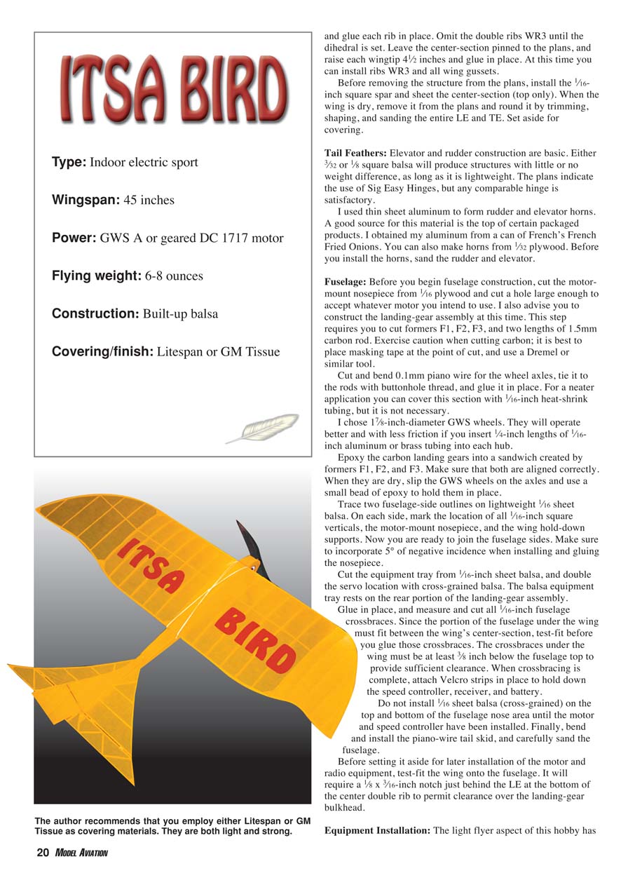
Since weight is critical, use a lightweight covering such as Litespan or GM (Gas Model) Tissue; both are heat-shrinkable but require that you apply Balsarite or Sig Stix-It to the framework. Cover only the top of the wing and elevator. Cover the rudder on both sides. Be extremely careful when applying heat to prevent warping.
Once the elevator and rudder are covered, install the hinges and horns. Do not cover the fuselage section under the wing or where the radio-equipment compartment is located. Glue the rudder and elevator to the fuselage.
Flying
Attach the wing using thin rubber bands. I found that two No. 18 bands tied together and crisscrossed over the wing work well. Before flying, make sure the balance is correct. If adjustment is needed, using Velcro permits the battery to be moved accordingly.
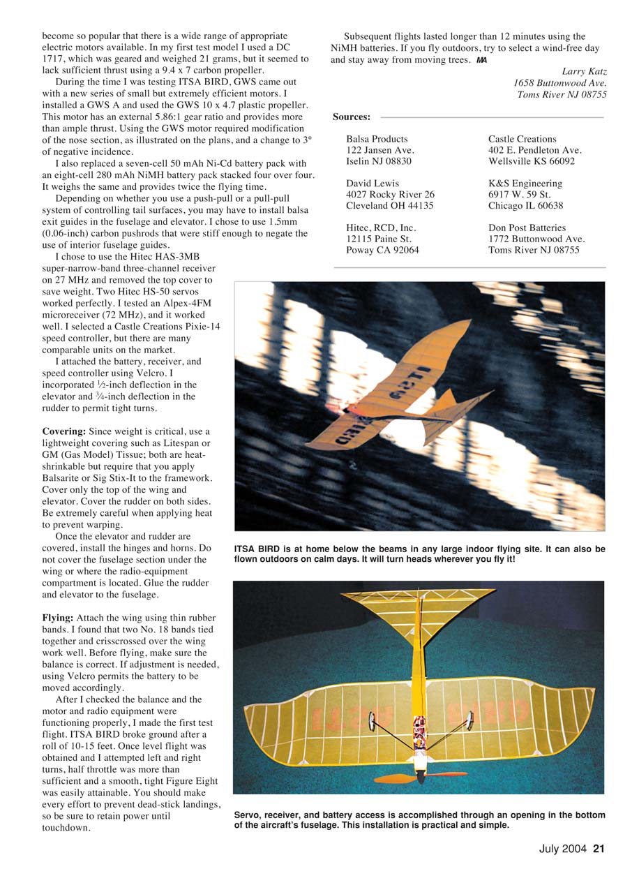
After I checked the balance and the motor and radio equipment were functioning properly, I made the first test flight. ITSA BIRD broke ground after a roll of 10–15 feet. Once level flight was obtained and I attempted left and right turns, half throttle was more than sufficient and a smooth, tight figure eight was easily attainable. You should make every effort to prevent dead-stick landings, so be sure to retain power until touchdown.
Subsequent flights lasted longer than 12 minutes using the NiMH batteries. If you fly outdoors, try to select a wind-free day and stay away from moving trees.
Larry Katz 1658 Buttonwood Ave. Toms River, NJ 08755
Sources
- Balsa Products
122 Jansen Ave. Iselin, NJ 08830
- David Lewis
4027 Rocky River 26 Cleveland, OH 44135
- Hitec, RCD, Inc.
12115 Paine St. Poway, CA 92064
- Castle Creations
402 E. Pendleton Ave. Wellsville, KS 66092
- K&S Engineering
6917 W. 59 St. Chicago, IL 60638
- Don Post Batteries
1772 Buttonwood Ave. Toms River, NJ 08755
Transcribed from original scans by AI. Minor OCR errors may remain.

