
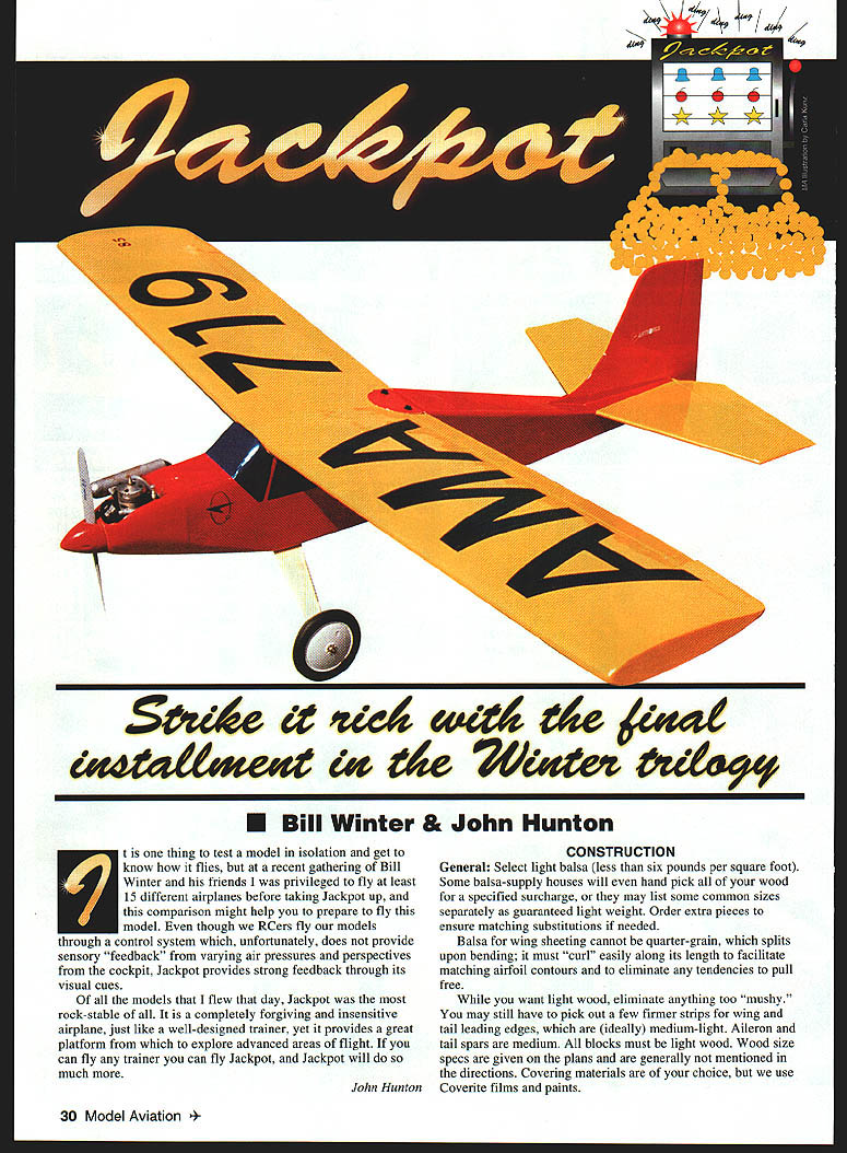
Jackpot
Strike it rich with the final installment in the Winter trilogy
Bill Winter & John Hunton
Bill Winter It is one thing to test a model in isolation and get to know how it flies, but at a recent gathering of Bill Winter and his friends I was privileged to fly at least 15 different airplanes before taking Jackpot up, and this comparison might help you prepare to fly this model. Even though we RCers fly our models through a control system which, unfortunately, does not provide sensory feedback from varying air pressures and cockpit perspectives, Jackpot provides strong feedback through its visual cues.
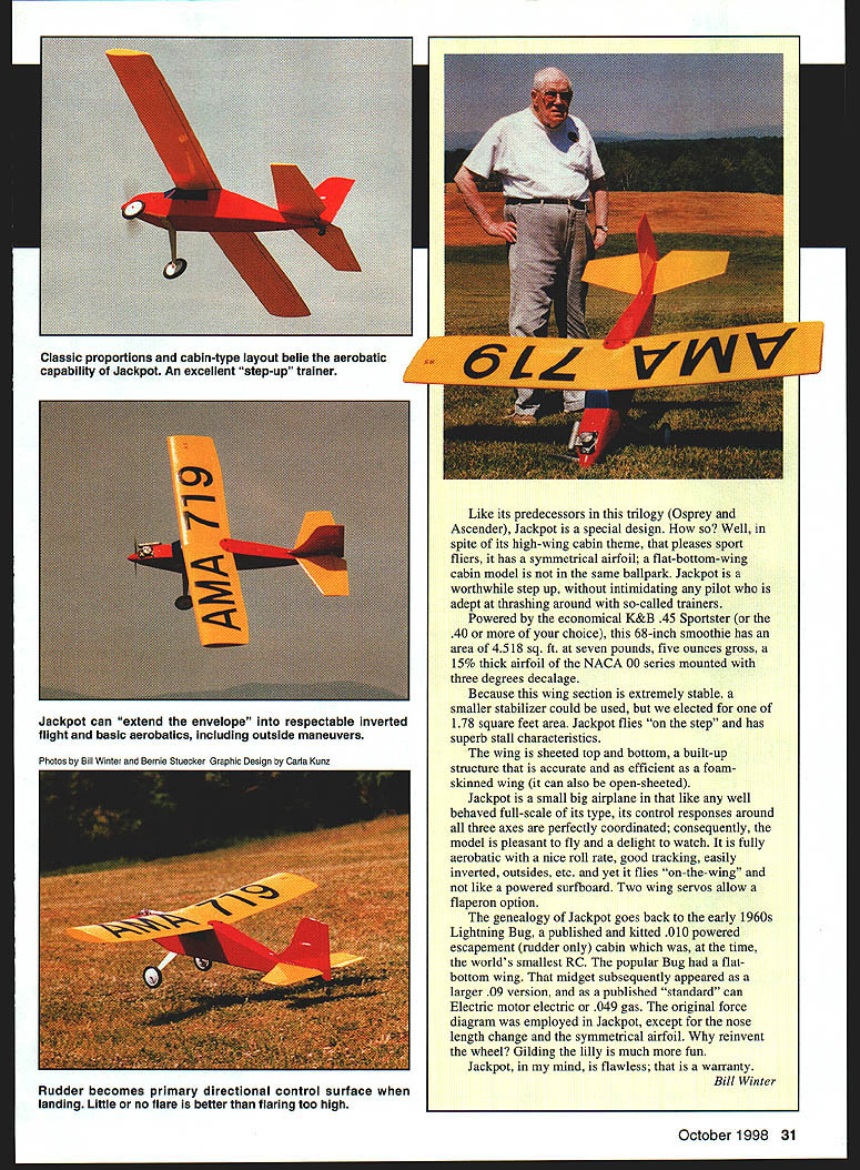
Of all the models I flew that day, Jackpot was the most rock-stable of all. It is a completely forgiving and insensitive airplane, just like a well-designed trainer, yet it provides a great platform from which to explore advanced areas of flight. If you can fly any trainer you can fly Jackpot, and Jackpot will do so much more.
John Hunton
CONSTRUCTION
#### General
- Select light balsa—less than six pounds per cubic foot. Some balsa suppliers will hand-pick wood for a surcharge or list common sizes guaranteed light. Order extra pieces for matching substitutions if needed.
- Balsa for wing sheeting must not be quarter-grain (which splits upon bending); it should curl easily along its length to match airfoil contours and avoid pulling free.
- Avoid overly mushy wood. You may need firmer strips for wing and tail leading edges (ideally medium-light). Aileron and tail spars are medium. All blocks must be light wood. Wood size specs are given on the plans.
- Covering materials are your choice; the authors used Coverite films and paints.
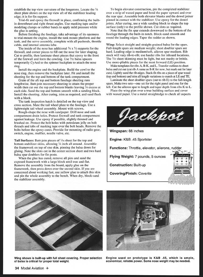
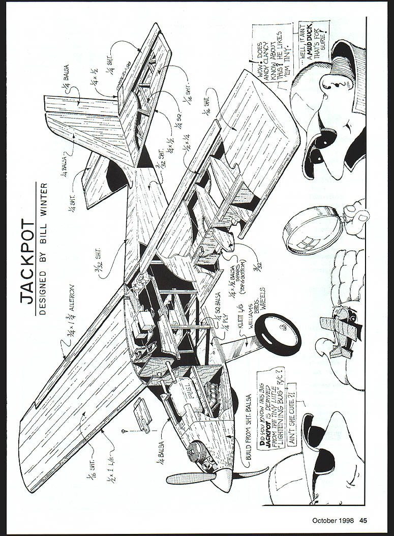
Jackpot is a special design: despite its high-wing cabin theme it uses a symmetrical NACA 00-series airfoil (15% thick) mounted with 3° decalage. Powered by the economical K&B .45 Sportster (or .40 or similar), this 68-inch model has 4.518 sq ft area and flies at about 7 lb 5 oz gross. The wing section is extremely stable; the chosen stabilizer area is 1.78 sq ft. Jackpot flies "on the step" and has superb stall characteristics. The wing is sheeted top and bottom (built-up structure) for accuracy and efficiency; it can also be open-framed. The model is fully aerobatic yet rock-stable and pleasant to fly. Two wing servos allow a flaperon option.
The design lineage goes back to the 1960s Lightning Bug. The original force diagram was employed in Jackpot with nose length changes and the symmetrical airfoil.
The frame has noteworthy features: optional open-framed wing; stabilizer sheeted top and bottom; aft top and bottom fuselage sheeting runs lengthwise. If wood is selected as indicated, gross weight is acceptable.
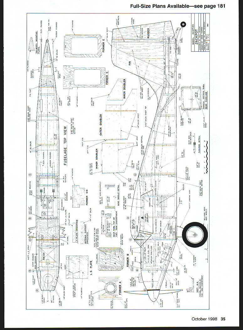
Fuselage
- Make thin cardboard side templates of the fuselage profile at the wing mount, using the front butt line of the side sheeting as a baseline. Cut another template for the aft end extending forward one station from the stabilizer leading edge. Use these templates to mark outlines and guarantee precise duplication of relative incidence angles of wing and stab.
- Do not complete assembly of the windshield area until holes for the two wing hold-down dowels have been drilled through the predrilled former holes into the wing "grabber" plate. Dowels are integral with the fuselage.
Construction steps:
- True the edges of the side sheeting by clamping a metal straightedge over the sheet and trimming with a #11 X-Acto™ knife. If you cannot get 48-inch balsa for the sides, butt-join sheeting at kerfed joints; use pins and/or masking tape to hold seams and join with cyanoacrylate (CyA) glue.
- Align the bottom edges of both side sheets, clamp to the bench (opposite sides up), and mark former positions with a soft pencil and T-square. Downthrust and right-side side thrust are provided by tilting and slanting the firewall.
- Preassemble each side as far as possible before joining. Cut inner and outer nose doublers, trial-fit, and attach outer doublers with spray contact cement (e.g., 3M™); repeat for inner doublers. Pin, then CyA all longerons and cross pieces into place.
- Cut firewall, bulkheads, formers, and plywood parts. Drill all required holes (fuel lines, throttle linkage, etc.) in the firewall. Drill for blind nuts in the landing gear plate and install them with epoxy.
- Place completed sides flat on the bench and trial-fit key bulkheads to one side at a time. Install formers C and E on one side only using yellow (carpenter's) glue to allow shifting for precise positioning. Former C sits 1/4" above the bottom line of the side sheet; former E is flush with the top surface of the bottom sheeting.
- Lay down the remaining side, trial-fit the completed first side with the projecting firewall and former, then glue into place. Ensure formers reach rock bottom and check alignment repeatedly with a small triangle.
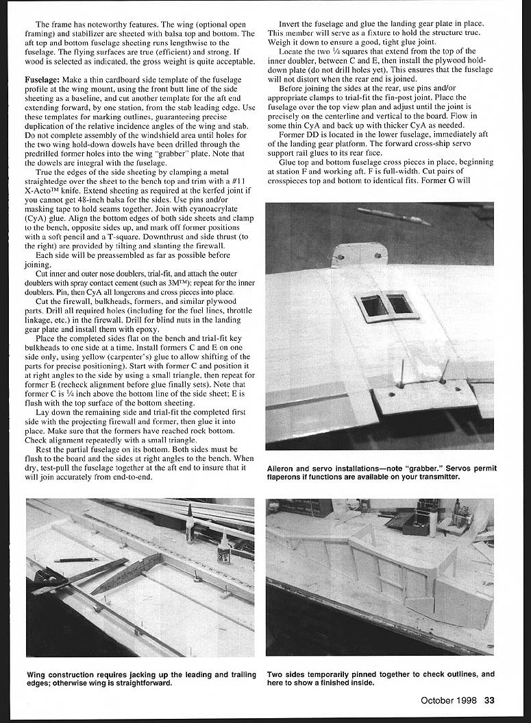
- Rest the partial fuselage on its bottom, ensuring both sides are flush to the board and at right angles. When dry, test-pull the fuselage at the aft end to ensure accurate join.
- Invert the fuselage and glue the landing gear plate in place; weigh it down for a tight joint.
- Locate the two 1/4" squares that extend from the top of the inner doubler between C and E, then install the plywood hold-down plate (do not drill holes yet) to prevent distortion when joining the rear end.
- Before joining the sides at the rear, trial-fit the fin-post joint with pins/clamps. Place the fuselage over the top-view plan and adjust until the joint is precisely on the centerline and vertical. Flow thin CyA and back up with thicker CyA as needed.
- Former D is located in the lower fuselage immediately aft of the landing gear platform. The forward cross-ship servo support rail glues to its rear face.
- Glue top and bottom fuselage cross pieces in place, beginning at station F and working aft. F is full-width. Cut pairs of crosspieces top and bottom to identical fits. Former G establishes the top-view curvature of the longerons. Locate the 1/4" sheet plate aft of the stabilizer leading edge—this is for fin support.
- Trial-fit and epoxy the firewall in place, confirming downthrust and right thrust angles. Use masking tape, modeling clamps, or rubber bands to apply mild pressure while glue sets.
- Take advantage of the open fuselage to trial-mount engine, install tank mount platform and tank, servo assembly with pushrods, throttle cable, and internal antenna tube.
- Inside the nose, add 1/4" x 1/2" supports for the firewall and corner pieces to fill out the nose for shaping. Laminate sheet pieces to the front of the firewall to form the cowling. Use 3/32" balsa spacers temporarily CyAed to the spinner backplate to attach the nose ring.
- Install the engine and backplate. Build the cowl to the nose ring, then remove the backplate later. Fit and install sheeting for the top and bottom of the tank compartment.
- Grain of aft top and bottom fuselage sheeting runs lengthwise. Butt-join sheeting to attain proper width; cut top and bottom blanks leaving 1/4" excess per side. Sand blanks with a block, install sheeting, let cure, then trim and sand flush.
- The tank inspection hatch is detailed on the plans. Mate the tailwheel plate to the fuselage; use a lightweight tailwheel assembly mounted with screws.
- Rough-shape the nose with sandpaper. Drill nose and tank compartment drain holes. Protect firewall and tank compartment against leakage—use slightly thinned epoxy brushed on. Protect bolt holes with petroleum jelly on bolt threads and tabs of masking tape over bolt heads; remove bolts before epoxy cures.
- Provide mounting for radio gear, switch, engine, muffler, needle valve, etc.
Tail Surfaces
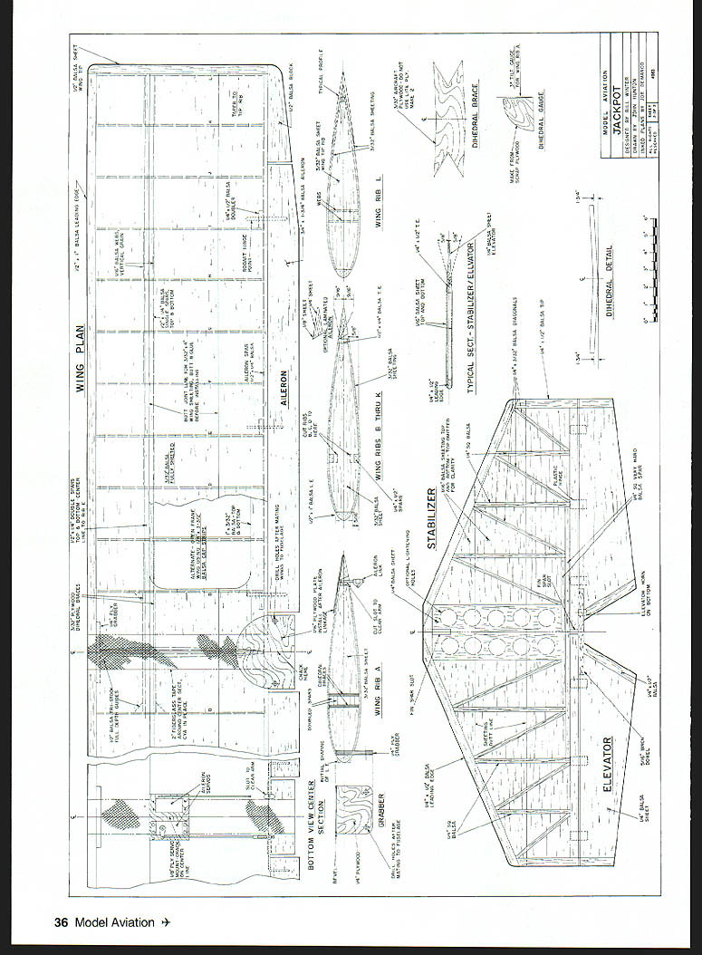
- Butt-join 1/16" sheet pieces for top and bottom stabilizer skins, allowing 1/4" all around. Assemble the framework on top of one skin, pinning the balsa for gluing. Note slots cut in the center section sheet and two hard balsa spar doublers for fin posts.
- When glue cures, remove pins and sand the exposed framework flat. Remove assembly from the board, apply glue to framework, then press over the second skin. If working slowly, use yellow glue for the second skin and pin the assembly to the bench. When dry, block-sand the stabilizer.
- For elevator construction: pin the completed stabilizer over a strip of waxed paper and bend the paper upward over the rear spar. Assemble elevator blanks and the dowel joiner pinned in contact with the stabilizer. Use epoxy for dowel joints. After curing, use a wide sanding block to shape the top surface only to the profile shown on the plans. Cut slots as required.
- The fin spar extends downward to the bottom of the fuselage through the built-in notch. Block-sand and round leading edges; taper the rudder as shown.
Wing
- Select straight, straight-grained balsa for spars. Full-length spars are medium weight; short doubler spars are hard. Leading edge should be medium-soft; aileron spar medium. Rib stock will vary; use harder ribs inboard. The 3/32" sheet skinning must be light but not mushy or brittle. Use more pliable pieces for the forward leading-edge position.
- Make templates for ribs A, B–K, and L. Transfer cut lines to sheet balsa and cut out. Lightly sand rib edges. Stack-fit ribs on a piece of spar wood and trim length variations to match at LE and TE.
- Laminate short doubler spars out to rib E to the full-length spars. Make two sets, one for each panel. Cut aileron spar to length and taper depth from ribs K to L.
Building sequence:
- Place the wing plan over a true building surface covered with waxed paper. Pin bottom spar in place.
- Add 5/16" spacers (approx. four places) to support the leading edge and rib dowels; slip ribs onto the spar to position properly. Install the aileron spar similarly on 5/16" jacks.
- Note joiner and grabber guides (1/2" triangle stock). Glue guides to ribs A and B where indicated, allowing exactly 7/8" spacing for the joiners and 1/4" for the grabber (both slipped into place after completion of wing panels). Install all ribs; the center rib is tilted for dihedral.
- Dry-fit the top spar. Press down on the top of the spar with a straightedge to avoid surface undulation, then glue.
- Install 1/16" balsa spar webs with grain vertical. Install doublers at hinge points. True the panel with a sanding block.
- Slope the top of the aileron spar but leave the leading edge square for now. If you prefer not to fully sheet the wing, run a 1 x 3/32" piece along the aileron spar and sheet the D-tube front portion as usual. Add center section sheeting to rib C and 1/32" scrap strips to remaining ribs.
- Invert the wing panel, pin down, and sheet the bottom. For fully sheeted wings the surface comprises three four-inch sheets per panel. Trim the leading-edge sheet to run from the leading edge to the middle of the spar. Apply yellow glue to the ribs, butt the sheet to the leading edge, pin, and glue with CyA. Pull the sheet down over the ribs to the spar, pin, and glue. Ensure the sheet seats tightly to the leading edge of the ribs.
- Butt-join two sheets for the rear portion of the wing flat on the bench with CyA and pre-sand the joint. Run a bead of yellow glue along all ribs and the aileron spar. Install the rear sheet assembly by pinning at the spar, pulling down over ribs, and pinning at the aileron spar. Repeat for the opposite side.
- Mark the leading edge for initial trimming with a razor plane. Sand the leading edge to the section shown on the plans using a long sanding block. Break the trailing edge down to a crisp thin edge.
- Install ailerons and hinge with CA hinges or cloth hinges sealed with thin CyA. Install aileron servos and run pushrods with Z-bends to the horns. Two wing servos allow a flaperon option if desired.
- Make templates and trial-assemble wing panels with joiners before gluing. Prop up panels at indicated dihedral distances and check for sweep. Disassemble, apply epoxy to joiners and facing ribs, then reassemble with dihedral blocks under the tips. Hold together with pins/tape until set. Fill crevices and apply a 2" medium/light fiberglass strip over the center seam top and bottom.
- Cut and install the grabber (do not drill grabber holes until ready). Install the aileron actuator, noting the hingeline is near the top surface. Apply a drop of oil to the wire in each sheath. Cut the wing to accept the actuator and cut bottom surfaces to allow the arm to swing fully. Cut the 1/16" plywood top plate, crack along its center if required, and install carefully to avoid gluing the actuator.
Wing-to-fuselage fit:
- Seat the wing by running masking tape chordwise where it meets the fuselage. Coat the tape with lipstick, mount the wing, press down, remove the wing and shave material where needed. Repeat until a solid seat is obtained. Remove tape, mark precise center points on wing and fuselage, mate wing checking squareness from tips to tail, then tape or tack-glue in place.
- Drill 3/16" through the wing perpendicular to the wing surface into the hold-down plate for rear hold-down screws. Enlarge wing holes to 1/4". Tap the hold-down block 1/4-20 and install nylon wing screws. Drill four holes through the forward cabin former into the grabber. Epoxy 1/4" dowels into the fuselage.
Final Assembly
- Install radio compartment shelves and servos. Ensure control throws are correct and pushrods operate freely. Place battery and receiver to achieve proper center of gravity (CG) and balance.
- Stabilizer and fin: build flat on the bench, sheet top and bottom with 1/16" balsa and sand to section. Hinge and install fin per plans. Cut away covering underneath the stabilizer within fuselage outlines. Cut a 1/4" wide strip from the top of the stabilizer centerline for alignment reference. Mount stabilizer with yellow glue, rechecking alignment. Use a triangle to set fin vertical to stabilizer and glue in place.
- Elevators and rudder: install elevators before the rudder. Install horns and trial-fit surfaces before gluing hinges. Use slow-curing epoxy for actuator arms and hinges where specified.
- Landing gear: install fixed gear to the plywood plate with rubber shock mounting. Bend wire gear to plan shape; install wheels and pants if desired. Use a sturdy tailwheel assembly for taildragger setup and mount with screws.
- Install aileron actuator arms and ailerons one at a time; epoxy actuator arms and install hinges. Install engine, hook up fuel lines and throttle linkage. Install landing gear and wheels.
- Install RC system in foam; check operation of all control surfaces for free movement and proper throws.
Covering and Finish
- Cover with iron-on film such as Coverite. The design was based on film covering—no cloth, dope, or heavy paint is required. Use BalsaKote to improve film adhesion where needed.
- Sand all surfaces with fine paper on a block. Round off the fuselage as shown on plans but leave the cross-section square at the wing trailing edge, stabilizer mount, and landing gear block.
- Mask and paint carefully to avoid excessive weight.
Flying / Test Flying
- Engine and props: authors used a 12 x 5 plastic prop with the K&B Sportster. If you normally use a 10 x 6, try an 11 x 5 or 12 x 5 depending on configuration. Increasing diameter or adjusting pitch can improve thrust-to-drag matching.
- CG: if the center of gravity is not correct, correct with ballast in the nose. Lighter engines may require ballast; allowance is made for heavier four-stroke or larger-displacement engines.
- Taxi tests: become familiar with its taildragger personality and throttle responses. Use up elevator to keep the tail down initially and avoid noseroll. Make progressively faster simulated runs into the wind to feel steering corrections.
- Takeoff: apply power smoothly to full to get rolling. As speed builds the tail will come up on its own. Avoid sudden power application; sudden tail lift can cause a pronounced left swing. Do not pull the airplane off the ground—allow it to fly off smoothly or briefly hold some up elevator until tracking is stable.
- In flight: Jackpot has excellent turn qualities; use coordinated rudder in turns. Consider CAR (Coupled Aileron and Rudder) set around 50% for assistance. With flaperons, set CAR to 100% rudder due to loss of aileron effectiveness when flaps are down. Feel out elevator trim mixing with flaperon deployment if used.
- Landings: rely mainly on rudder for directional control. Use a slight flare at touchdown and stay on the rudder. Do not flare high—too much flare causes a high bounce.
- Handling: Jackpot is rock-stable, forgiving, provides strong visual feedback via its cabin layout, and yet remains fully aerobatic with good roll rate, tracking, and inverted capability.
Credits
- Designed by Bill Winter
- Photos: Bill Winter, Bernie Stuecker
- Graphic design: Carla Kunz
Contact: Bill Winter 12811 Melville Ln. Fairfax, VA 22033
John Hunton 9154 Rixeyville Rd. Rixeyville, VA 22737
Transcribed from original scans by AI. Minor OCR errors may remain.

