
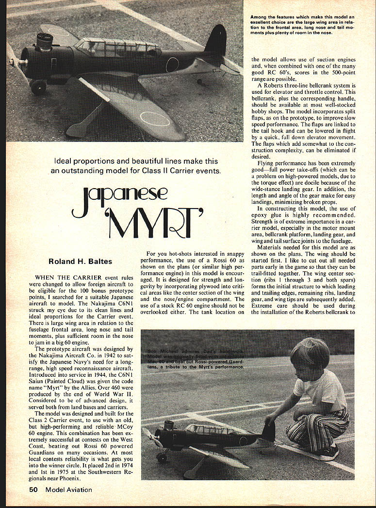
Japanese 'MYRT'
Roland H. Baltes
WHEN THE CARRIER event rules were changed to allow foreign aircraft to be eligible for the 100 bonus prototype points, I searched for a suitable Japanese aircraft to model. The Nakajima C6N1 struck my eye due to its clean lines and ideal proportions for the Carrier event. There is large wing area in relation to the fuselage frontal area, long nose and tail moments, plus sufficient room in the nose to jam in a big 60 engine.
The prototype aircraft was designed by the Nakajima Aircraft Co. in 1942 to satisfy the Japanese Navy's need for a long-range, high speed reconnaissance aircraft. Introduced into service in 1944, the C6N1 Saiun (Painted Cloud) was given the code name "Myrt" by the Allies. Over 460 were produced by the end of World War II. Considered to be of advanced design, it served both from land bases and carriers.
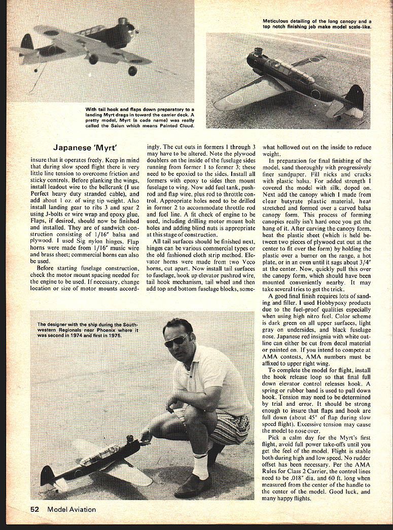
The model was designed and built for the Class II Carrier event, to use with an old, but high-performing and reliable McCoy 60 engine. This combination has been extremely successful at contests on the West Coast, beating out Rossi 60 powered Guardians on many occasions. At most local contests reliability is what gets you into the winner circle. It placed 2nd in 1974 and 1st in 1975 at the Southwestern Regionals near Phoenix.
For you hot-shots interested in snappy performance, the use of a Rossi 60 as shown on the plans (or similar high-performance engine) in this model is encouraged. It is designed for strength and longevity by incorporating plywood into critical areas like the center section of the wing and the nose/engine compartment. The use of a stock RC 60 engine should not be overlooked either. The tank location on the model allows use of suction engines and, when combined with one of the many good RC 60s, scores in the 500-point range are possible.
A Roberts three-line bellcrank system is used for elevator and throttle control. This bellcrank, plus the corresponding handle, should be available at most well-stocked hobby shops. The model incorporates split flaps, as on the prototype, to improve slow speed performance. The flaps are linked to the tail hook and can be lowered in flight by a quick, full down elevator movement. The flaps, which add somewhat to the construction complexity, can be eliminated if desired.
Flying performance has been extremely good—full power take-offs (which can be a problem on high-powered models, due to the torque effect) are docile because of the wide-stance landing gear. In addition, the length and angle of the gear make for easy landings, minimizing broken props.
In constructing this model, the use of epoxy glue is highly recommended. Strength is of extreme importance in a carrier model, especially in the motor mount area, bellcrank platform, landing gear, and wing and tail surface joints to the fuselage.
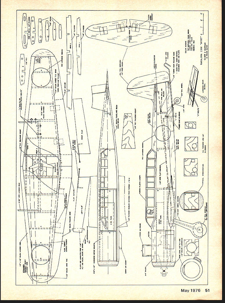
Materials needed for this model are as shown on the plans. The wing should be started first. I like to cut out all needed parts early in the game so that they can be trail-fitted together. The wing center section (ribs 1 through 3 and both spars) forms the initial structure to which leading and trailing edges, remaining ribs, landing gear, and wing tips are subsequently added. Extreme care should be used during the installation of the Roberts bellcrank to insure it operates freely. Keep in mind during slow speed flight very little line tension is available to overcome friction in sticky controls.
Before planking the wings install leadout wire and bellcrank. Use Perfection heavy-duty stranded cable. Add about 1/2 oz. wing-tip weight. Also install landing gear, ribs 3, spar 2, using J-bolts, wire wrap and epoxy glue. Flaps, if desired, should now be finished and installed. Sandwich construction consisting of 1/16" balsa and plywood is used. Sig nylon hinges are recommended. Flap horns are made from 1/16" music wire and brass sheet; commercial horns can also be used.
Before starting fuselage construction check motor-mount spacing needed for the engine used. If necessary change the location or size of motor mounts accordingly. Meticulous detailing, long canopy and a top-notch finishing job make the model scale-like. Cutouts of formers through 3 may have been altered. Note plywood doublers inside fuselage sides. No continuing article text appears on this scanned page — it contains the plan drawings and component labels for the Nakajima C6N1 "Myrt" (scale plans) rather than additional article prose. The cutouts in formers 1 through 3 may have to be altered. Note the plywood doublers on the inside of the fuselage sides running from former 1 to former 3; these need to be epoxied to the sides. Install all formers with epoxy to sides then mount fuselage to wing. Now add fuel tank, pushrod and flap wire, plus rod to throttle control. Appropriate holes need to be drilled in former 2 to accommodate throttle rod and fuel line. A fit check of engine to be used, including drilling motor-mount bolt holes and adding blind nuts is appropriate at this stage of construction.
All tail surfaces should be finished next. Hinges can be various commercial types or the old-fashioned cloth-strip method. Elevator horns were made from two Veco horns, cut apart. Now install tail surfaces to fuselage, hook up elevator pushrod wire, tail-hook mechanism, tail wheel and then add top and bottom fuselage blocks, somewhat hollowed out on the inside to reduce weight.
In preparation for final finishing of the model, sand thoroughly with progressively finer sandpaper. Fill nicks and cracks with plastic balsa. For added strength I covered the model with silk, doped on. Next add the canopy which I made from clear butyl plastic material, heat-stretched and formed over a carved balsa canopy form. This process of forming is somewhat like that used on one copy I had built. After carving the canopy form, heat the plastic sheet (which is held between two pieces of plywood cut out at the center to fit over the form) by holding the plate or iron over a burner on the range, a hot plate, or in one oven until it sags about 3/4" at the center. Now quickly pull this over the canopy form, which should have been mounted conveniently nearby. It may take several tries to get the trick.
A good final finish requires lots of sanding and filler. I used Hobbycote products due to the fuel-proof qualities especially when using high-nitro fuel. Color scheme is dark green on all upper surfaces, light gray on undersides, and black fuselage nose. Japanese red insignia with white outline can either be cut from decal material or painted on. If you intend to compete at AMA contests, AMA numbers must be affixed to upper right wing.
To complete the model for flight, install the hook-release loop so that final full-down elevator control releases hook. A spring or rubber band is used to pull down the hook. Tension may need to be determined by trial and error. It should be strong enough to insure that flaps and hook are full down (about 45° of flap during slow-speed flight). Excessive tension may cause the model to nose over.
Pick a calm day for the Myrt's first flight; avoid full-power takeoffs until you get the feel of the model. Flight is stable both during high and low speed. No rudder offset has been necessary. Per the AMA rules for Class 2 Carrier, the control lines need to be .018" dia. and 60 ft. long when measured from the center of the handle to the center of the model. Good luck, and many happy flights.
Transcribed from original scans by AI. Minor OCR errors may remain.

