

The Jetster
Developed from scratch on M.A.'s assignment, this airplane is designed for the pattern/sport flier as a relatively easy way to try ducted-fan power. Is it maneuverable—or a flying brick? How does knife-edge flight grab you? By Dick Sarpolus
Introduction
It is apparent that practical ducted-fan power units are now available for the modeler who wishes to simulate jet-powered flight. Most of the pioneering effort has been done by scale modelers looking for realistic jet aircraft projects. The Jetster was designed for the pattern and/or sports flier as a relatively easy way to try ducted-fan power systems; I wanted to see if such a system was suitable for a non-scale, fun-flying aircraft. This model has been flown from grass fields and in windy weather; it has an effective muffler and it does fly very well. There is no denying the extra complexity of a ducted fan, but they do work, performance is good, and you can have that jet-age appearance.
Background
Ducted fans are not new; Berkeley (a long-gone kit manufacturer) had ducted-fan kits on the market back in the 1950s. As I recall, the fan was simply stamped from sheet aluminum with twisted blades, intended for use on .049 engines. The aircraft structures were stick-and-tissue for light weight, and the models were flown as free flights. Over the years many ducted-fan projects have appeared in the magazines with a wide variety of fan and duct designs; structures usually aimed for light weight as very little fan thrust was available.
Jim Scozzafava brought out his Scozzi unit several years ago; this unit has been taken over by Jet Hanger Models. A well-known manufacturer, Midwest Products, is offering the Axiflo fan kit (as designed by Bob Kress); Editor, World Engines has developed an excellent unit, but has not introduced it. The Scozzi fan has been well demonstrated by Bob Violet of pylon racing fame in his A-4 Skyhawk, which has placed highly in many scale contests and is available as a kit. Midwest is also producing a scale kit for their Axiflo fan, the Heinkel He 162, as designed by well-known stand-off scale modeler Nick Ziroli. I would not presume to say either unit was better. I have only used the Axiflo fan on this model and will, of course, comment on my experience with it.
Design Goals
The basic design aims of the Jetster were to get a ducted-fan model with:
- good aerobatic flying capability,
- relatively easy construction,
- an uncomplicated and accessible fan installation,
- a modern, jet-styled appearance.
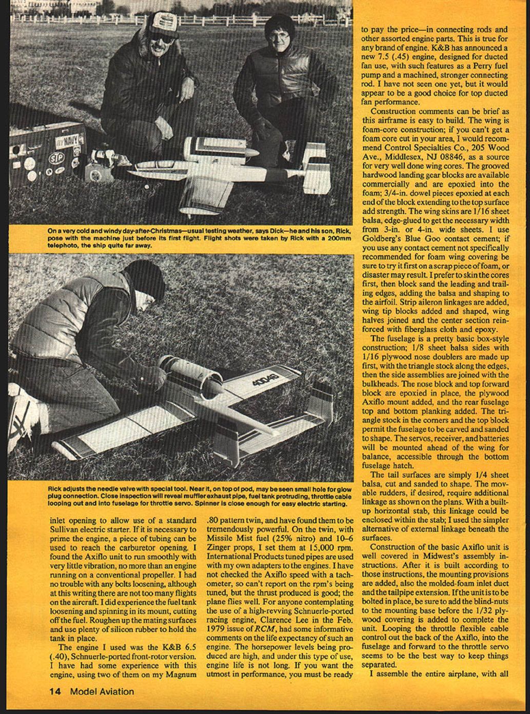
Wing area was configured at 615 sq. in., typical for a .40-powered pattern model. The airfoil is 16% thick; a semi-symmetrical section provides more lift and easier landings. The wing planform has a straight trailing edge and a swept-back leading edge. Foam-core construction and strip ailerons are used for ease of assembly.
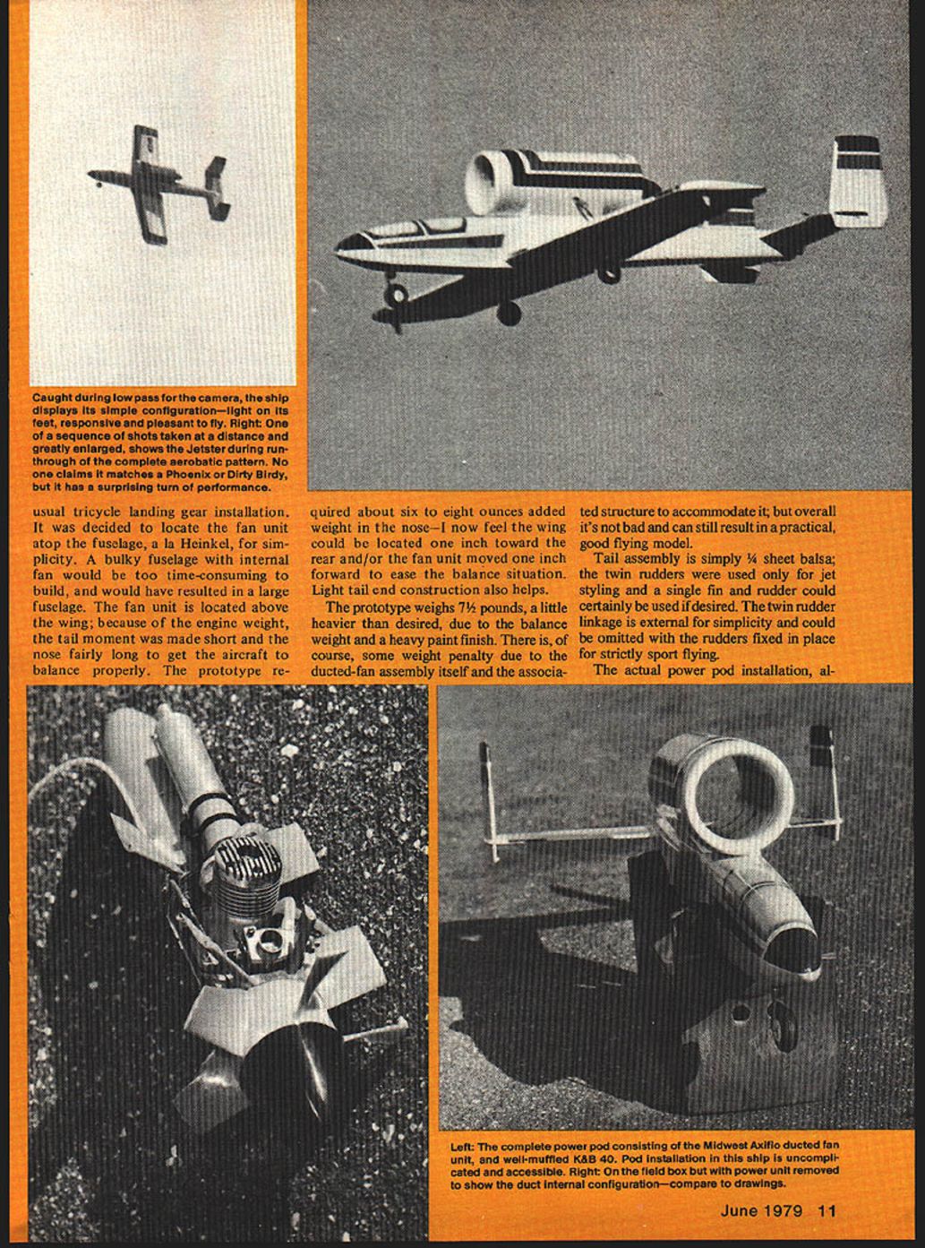
Fuselage design is a compromise: a low-wing configuration is used for pattern flying performance and for a tricycle landing gear installation. The fan unit was located atop the fuselage, a la Heinkel, for simplicity. A bulky fuselage with an internal fan would be too time-consuming to build and would have resulted in a large fuselage. The fan unit is located above the wing; because of the engine weight, the tail moment was made short and the nose fairly long to get the aircraft to balance properly.
The prototype required about six to eight ounces of added weight in the nose— I now feel the wing could be located one inch toward the rear and/or the fan unit moved one inch forward to ease the balance situation. Light tail-end construction also helps.
The prototype weighs 7½ pounds, a little heavier than desired due to the balance weight and a heavy paint finish. There is, of course, some weight penalty due to the ducted-fan assembly itself and the associated structure to accommodate it; but overall it's not bad and can still result in a practical, good-flying model.
Tail assembly is simply 1/4" sheet balsa; the twin rudders were used only for jet styling and a single fin and rudder could certainly be used if desired. The twin-rudder linkage is external for simplicity and could be omitted with the rudders fixed in place for strictly sport flying.
Power Pod and Muffler
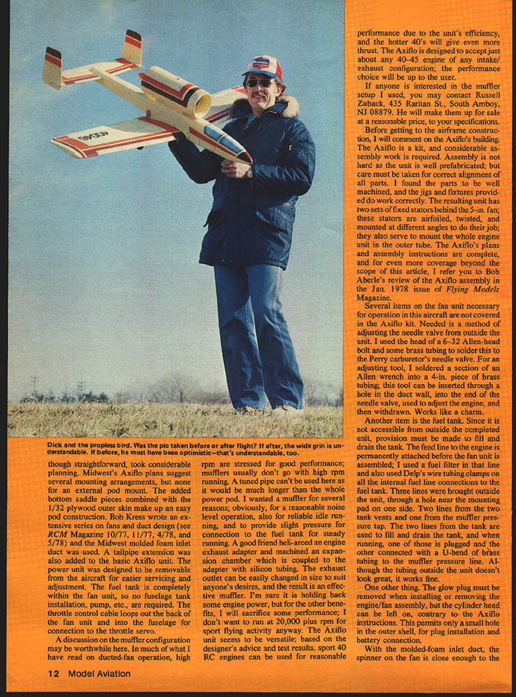
Power pod installation
The actual power pod installation, although simple and readily accessible, took considerable planning. Midwest's Axiflo plans suggest several mounting arrangements, but none for an external pod mount. The added bottom saddle pieces combined with the 1/32" plywood outer skin make up an easy pod construction. Bob Kress wrote an extensive series on fans and duct design (see RCM Magazine 10/77, 11/77, 4/78, and 5/78) and the Midwest molded-foam inlet duct was used. A tailpipe extension was also added to the basic Axiflo unit. The power unit was designed to be removable from the aircraft for easier servicing and adjustment. The fuel tank is completely within the fan unit, so no fuselage tank installation, pump, etc., are required. The throttle control cable loops out the back of the fan unit and into the fuselage for connection to the throttle servo.
Muffler configuration
A discussion on the muffler configuration may be worthwhile. In much of what I have read on ducted-fan operation, high rpm are stressed for good performance; mufflers usually don't go with high rpm running. A tuned pipe can't be used here as it would be much longer than the whole power pod. I wanted a muffler for several reasons:
- to reduce noise for reasonable operation,
- for reliable idle running,
- to provide slight pressure for connection to the fuel tank for steady running.
A good friend machined an engine exhaust adapter and an expansion chamber which is coupled to the adapter with silicone tubing. The exhaust outlet can be easily changed in size to suit anyone's desires, and the result is an effective muffler. I'm sure it holds back some engine power, but for the other benefits I will sacrifice some performance; I don't want to run at 20,000-plus rpm for sport flying activity anyway.
The Axiflo unit seems to be versatile; based on the designer's advice and test results, sport .40 RC engines can be used for reasonable performance due to the unit's efficiency, and the hotter .40s will give even more thrust. The Axiflo is designed to accept just about any .40–.45 engine of any intake/exhaust configuration; the performance choice will be up to the user.
If anyone is interested in the muffler setup I used, you may contact Russell Zuback, 435 Raritan St., South Amboy, NJ 08879. He will make them up for sale at a reasonable price, to your specifications.
The Axiflo Unit and Modifications
Before getting to the airframe construction, a few comments on the Axiflo's building are in order. The Axiflo is a kit, and considerable assembly work is required. Assembly is not hard as the unit is well prefabricated, but care must be taken for correct alignment of all parts. I found the parts to be well machined, and the jigs and fixtures provided do work correctly. The resulting unit has two sets of fixed stators behind the 5-inch fan; these stators are airfoiled, twisted, and mounted at different angles to do their job; they also serve to mount the whole engine unit in the outer tube. The Axiflo's plans and assembly instructions are complete. For even more coverage beyond the scope of this article, see Bob Aberle's review of the Axiflo assembly in the Jan. 1978 issue of Flying Models Magazine.
Several items necessary for operation in this aircraft are not covered in the Axiflo kit:
- Needle-valve adjustment: I used the head of a 6-32 Allen-head bolt and some brass tubing to solder this to the Perry carburetor's needle valve. For an adjusting tool, I soldered a section of an Allen wrench into a 4-inch piece of brass tubing; this tool can be inserted through a hole in the duct wall, into the end of the needle valve, used to adjust the engine, and then withdrawn. Works like a charm.
- Fuel tank access: Since the tank is not accessible from outside the completed unit, provision must be made to fill and drain the tank. The feed line to the engine is permanently attached before the fan unit is assembled; I used a fuel filter in that line and Del's wire tubing clamps on all the internal fuel line connections to the fuel tank. Three lines were brought outside the unit, through a hole near the mounting pad on one side:
- two lines from the two tank vents, and
- one from the muffler pressure tap.
The two lines from the tank are used to fill and drain the tank; when running, one of those is plugged and the other connected with a U-bend of brass tubing to the muffler pressure line. Although the tubing outside the unit doesn't look great, it works fine.
- Glow plug: The glow plug must be removed when installing or removing the engine/fan assembly, but the cylinder head can be left on, contrary to the Axiflo instructions. This permits only a small hole in the outer shell, for plug installation and battery connection.
With the molded-foam inlet duct, the spinner on the fan is close enough to the inlet opening to allow use of a standard .80 pattern twin; I have found them to be tremendously powerful. On the twin, with Missile Mist fuel (25% nitro) and 10x6 Zinger props, I set them at 15,000 rpm. International Products tuned pipes are used with my own adapters to the engines. I have not checked the Axiflo speed with a tachometer, so can't report on the rpm being turned, but the thrust produced is good; the plane flies well.
For anyone contemplating the use of a high-revving Schnuerle-ported racing engine, Clarence Lee in the Feb. 1979 issue of RCM had some informative comments on the life expectancy of such an engine. The horsepower levels being produced are high, and under this type of use, engine life is not long. If you want the utmost in performance, you must be ready to pay the price—in connecting rods and other assorted engine parts. This is true for any brand of engine.
K&B has announced a new 7.5 (.45) engine, designed for ducted-fan use, with such features as a Perry fuel pump and a machined, stronger connecting rod. I have not seen one yet, but it would appear to be a good choice for top ducted-fan performance.
Construction
Construction comments can be brief as this airframe is easy to build.
Wing
- Foam-core construction; if you can't get a foam core cut in your area, I recommend Control Specialties Co., 205 Wood Ave., Middlesex, NJ 08846, as a source for very well-done wing cores.
- Grooved hardwood landing gear blocks are available commercially and are epoxied into the foam; 3/4-inch dowel pieces epoxied at each end of the block extending to the top surface add strength.
- Wing skins are 1/16-inch sheet balsa, edge-glued to get the necessary width from 3- or 4-inch wide sheets. I use Goldberg's Blue Goo contact cement; if you use any contact cement not specifically recommended for foam wing covering be sure to try it first on a scrap piece of foam, or disaster may result.
- I prefer to skin the cores first, then block-sand the leading and trailing edges, adding the balsa and shaping to the airfoil.
- Strip aileron linkages are added, wing tip blocks added and shaped, wing halves joined and the center section reinforced with fiberglass cloth and epoxy.
Fuselage
- Pretty basic box-style construction: 1/8-inch sheet balsa sides with 1/16-inch plywood nose doublers are made up first, with triangle stock along the edges, then the side assemblies are joined with the bulkheads.
- The nose block and top forward block are epoxied in place, the plywood Axiflo mount added, and the rear fuselage top and bottom planking added.
- The triangle stock in the corners and the top block permit the fuselage to be carved and sanded to shape.
- Servos, receiver, and batteries are mounted ahead of the wing for balance, accessible through the bottom fuselage hatch.
Tail
- Tail surfaces are simply 1/4-inch sheet balsa, cut and sanded to shape.
- Moveable rudders, if desired, require additional linkage as shown on the plans. With a built-up horizontal stab, this linkage could be enclosed within the stab; I used the simpler alternative of external linkage beneath the surfaces.
Mounting the Axiflo
Construction of the basic Axiflo unit is well covered in Midwest's assembly instructions. After it is built according to those instructions, the mounting provisions are added, also the molded-foam inlet duct and the tailpipe extension. If the unit is to be bolted in place, be sure to add the blind nuts to the mounting base before the 1/32-inch plywood covering is added to complete the unit. Looping the throttle flexible cable control out the back of the Axiflo, into the fuselage and forward to the throttle servo seems to be the best way to keep things separated.
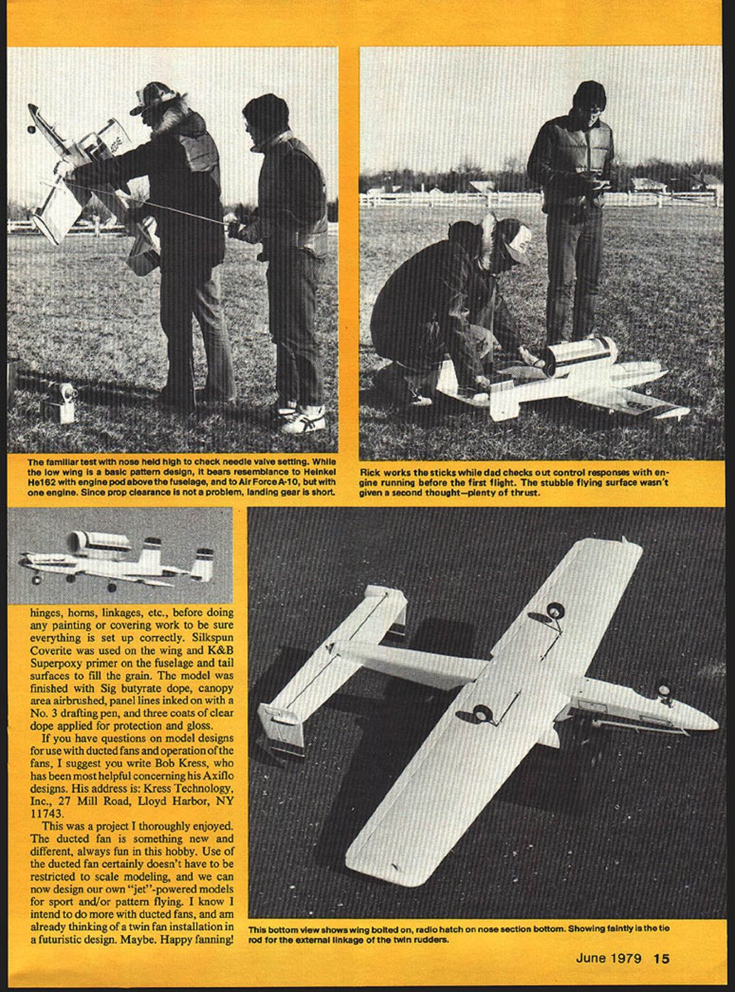
I assemble the entire airplane, with all hinges, horns, linkages, etc., before doing any painting or covering work to be sure everything is set up correctly.
Finish and Covering
- Silkspun Coverite was used on the wing and K&B Superpoxy primer on the fuselage and tail surfaces to fill the grain.
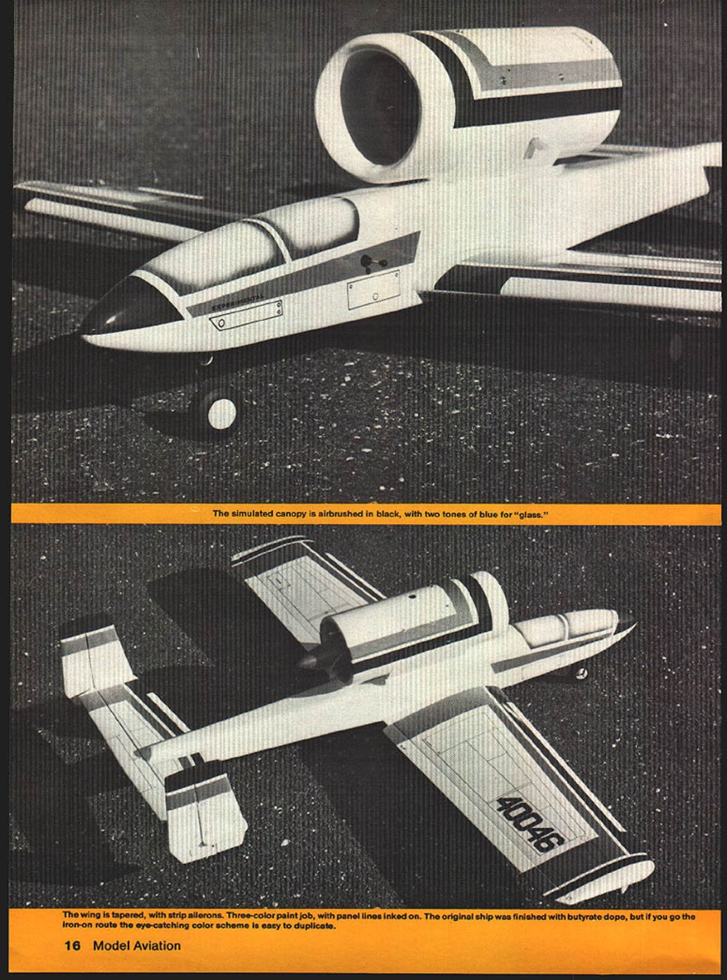
- The model was finished with Sig butyrate dope, canopy area airbrushed, panel lines inked on with a No. 3 drafting pen, and three coats of clear dope applied for protection and gloss.
The simulated canopy is airbrushed in black, with two tones of blue for "glass." The wing is tapered, with strip ailerons. Three-color paint job, with panel lines inked on. The original ship was finished with butyrate dope, but if you go the iron-on route the eye-catching color scheme is easy to duplicate.
References and Contacts
- Bob Kress, Kress Technology, Inc., 27 Mill Road, Lloyd Harbor, NY 11743 — helpful concerning Axiflo designs.
- Russell Zuback, 435 Raritan St., South Amboy, NJ 08879 — muffler setups made to order.
- For Axiflo assembly review: Bob Aberle, Flying Models Magazine, Jan. 1978.
- For duct/fan design articles: Bob Kress series in RCM Magazine (10/77, 11/77, 4/78, 5/78).
- Foam cores: Control Specialties Co., 205 Wood Ave., Middlesex, NJ 08846.
Conclusion
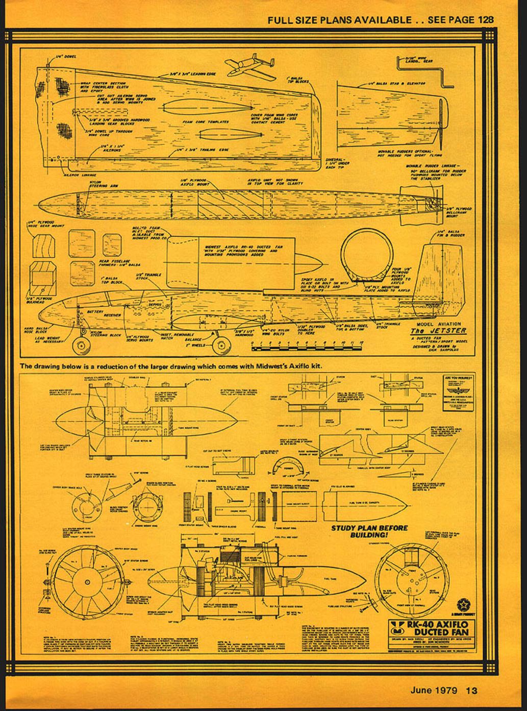
This was a project I thoroughly enjoyed. The ducted fan is something new and different, always fun in this hobby. Use of the ducted fan certainly doesn't have to be restricted to scale modeling, and we can now design our own "jet"-powered models for sport and/or pattern flying. I know I intend to do more with ducted fans, and am already thinking of a twin-fan installation in a futuristic design. Maybe. Happy fanning!
Transcribed from original scans by AI. Minor OCR errors may remain.

