
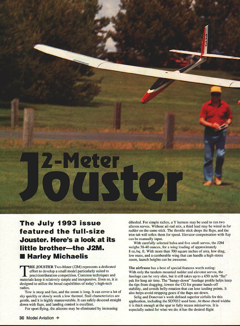
The July 1993 issue featured the full-size Jouster. Here's a look at its little brother—the J2M.
Harley Michaelis
The Jouster Two-Meter (J2M) represents a dedicated effort to develop a small model particularly suited to precision/duration competition. Common techniques and materials keep it relatively simple and inexpensive. Even so, it is designed to utilize the broad capabilities of today's high-tech radios.
Tow is steep and fast, and the zoom is long. It can cover a lot of sky quickly or slowly work a low thermal. Stall characteristics are gentle, and it is highly maneuverable. It can safely descend straight down with flaps, and landing control is excellent.
For sport flying, the ailerons may be eliminated by increasing dihedral. For simple radios, a Y-harness may be used to run two aileron servos. Without aileron–rudder mix, a third lead may be wired in for rudder on the same stick. The throttle stick drops the flaps, and the trim tab will reflex them for speed. Elevator compensation with flap can be manually input.
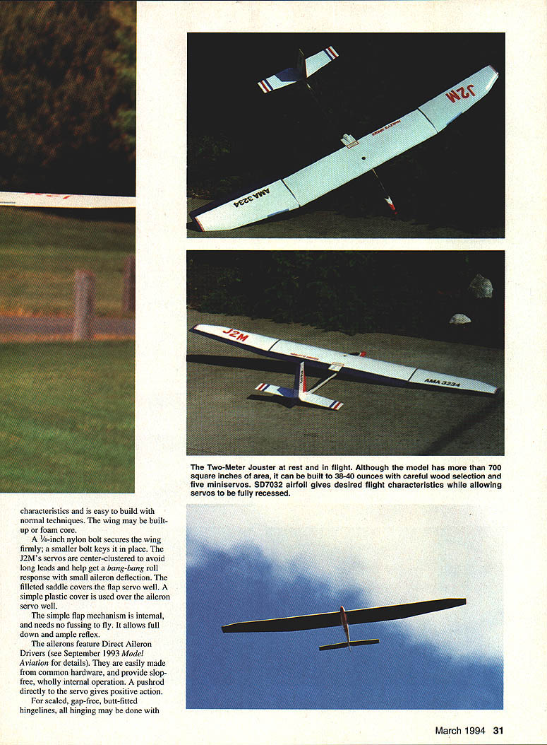
With carefully selected balsa and five small servos, the J2M weighs 38–40 ounces, for a wing loading of approximately 8 oz./sq. ft. With more than 700 square inches of area, low drag, low mass, and a camberable wing that can handle a high-stress zoom, launch heights can be awesome.
The airframe has a host of special features worth noting. With only tandem-mounted rudder and elevator servos, the fuselage can be very slim, yet it still takes up to a 650 mAh "flat" pack for long airtime. The hangy-down fuselage profile helps keep the tips from dragging, lowers the CG for greater hands-off stability, and avoids belly-rotation that can lose landing points. It also helps avoid stripping gears if the flaps are down.
Selig and Donovan's work defined superior airfoils for this application, including the SD7032 used here. At these chord widths it is thick enough at the spar to fully recess miniservos. It is especially suited for what we do; it has the desired flight characteristics and is easy to build with normal techniques. The wing may be built-up or foam core.
A 1/4-inch nylon bolt secures the wing firmly; a smaller bolt keys it in place. The J2M's servos are center-clustered to avoid long leads and help get a bang-bang roll response with small aileron deflection. The filleted saddle covers the flap servo well. A simple plastic cover is used over the aileron servo well.
The simple flap mechanism is internal and needs no fussing to fly. It allows full down and ample reflex. The ailerons feature Direct Aileron Drivers (see September 1993 Model Aviation for details). They are easily made from common hardware and provide slop-free, wholly internal operation. A pushrod directly to the servo gives positive action.
For sealed, gap-free, butt-fitted hingelines, all hinging may be done with Harley's hinges #50L317 (ACE R/C). No rounding, spacing, or beveling is needed. For deflection, hingelines can be hairline slits; hinges installed under slight tension help eliminate slop, bind, and flutter.
Faster cruising and dramatically reduced noise levels speak volumes about cleaner airflow.
Rudder is pull-pull cable operated. Light-frame stabilizer is rigidly mounted; a rigid pushrod assures well-defined neutral, positive action.
Construction
I have made the assumption that you have suitable tools, understand adhesives, know how to use a straightedge, and can align things; otherwise, have some building experience. Except where noted, use lightweight balsa. Fast-curing epoxy, assorted cyanoacrylate (CyA) glues, and basic adhesives are used for wood, structure, and foam work. Satellite City's UFO Hot Shot is recommended. 3M 77 spray adhesive works well to attach paper patterns and to stack sheeting.
Wicking techniques use several steps involving gluing parts together. Thin CyA means parts are pressed into position; glue applied to the edge joint between parts seeps into the joint by capillary action and penetrates both parts' surfaces, resulting in an exceptionally strong bond. Complete instructions and fiberglassing techniques are part of the Big Jouster plan.
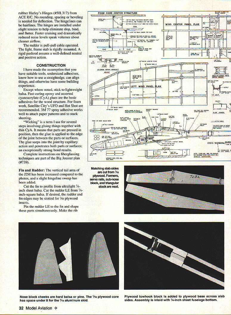
Fin / Rudder
- Vertical tail area: the J2M has increased vertical tail area compared to the photos; a slight hingeline sweep has been added.
- Cut fin profile from ultralight 1/16-inch sheet balsa. Cut rudder leading edge from 1/8-inch-square balsa.
- If desired, rudder and fin edges may be slotted for 1/32-inch plywood inserts.
- Pin rudder leading edge and fin shape parts simultaneously. Add notches and the other rudder parts. Assemble the parts to form the rudder "T" and run thin CyA down the tubes to join everything. Flatten and drill the ends for the cables.
- The slotted plywood piece that the T slips into is cut overwidth; after it is glued to the rudder, trim the excess wood. Add the cap in similar fashion, and notch the T for a vertical rudder key.
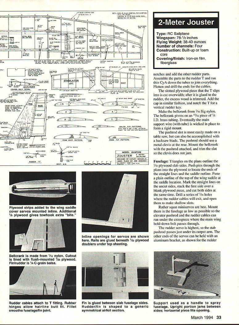
- Make the bellcrank from 1/16 Sig nylon. The bellcrank pivots on a 1/16 piece of 1/8 in. I.D. brass tubing. The main support wire (with tube) is wicked in place to form a rigid mount.
- The pushrod slot is most easily made on a table saw, but can also be accomplished with a hacksaw blade. Use a metal clevis at the rear of the pushrod. Mount the bellcrank with the pushrod attached and trim the slot so the clevis does not jam.
Fuselage
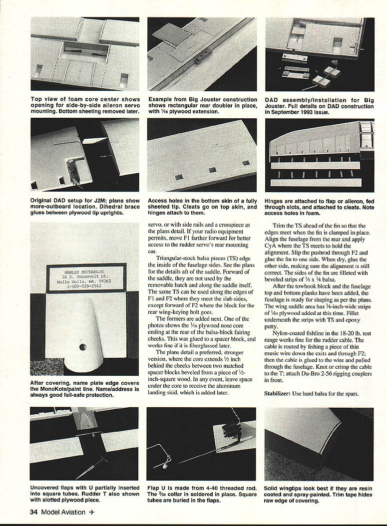
- Triangles on the plans outline the 1/16 plywood slab sides. Push pins through the plans into the plywood to locate the ends of the straight lines and the saddle outline. Paste a plain outline of the top of the wing saddle at the saddle location.
- Mark the straight lines on the uncut sides, stack the first side over a blank plywood piece, and cut both sides at the same time.
- Drill a series of 1/16 holes where the rudder cables will exit, and open them to make shallow slots.
- Rather squat miniservos are best. Mount them as low as possible so the elevator pushrod and the rudder cables can run under the crosspiece where the main wing hold-down bolt passes through.
- The rudder servo is highest, so the stab pushrod passes just under its output arm. The other ends of the servos can be held with an aluminum bracket, or with side rails and a crosspiece as the plans detail. If your radio equipment permits, move F1 farther forward for better access to the rudder servo's rear mounting ear.
- Triangular-stock balsa pieces (TS) edge the inside of the fuselage sides. See the plans for details at the saddle. Forward of the saddle, they are not used by the removable hatch and along the saddle itself. The same TS can be used along the edges of F1 and F2 where they meet the slab sides, except forward of F2 where the block for the rear wing-keying bolt goes.
- Add the formers next. One method uses a 1/16 plywood nose core ending at the rear of the balsa-block fairing cheeks; this can be glued to a spacer block and fiberglassed later. The preferred, stronger version extends the core 1/8 inch behind the cheeks between two matched spacer blocks beveled from 1/2-inch-square wood.
- Leave space under the core to receive the aluminum landing skid, which is added later.
- Trim the TS ahead of the fin so that the edges meet when the fin is clamped in place. Align the fuselage from the rear and apply CA where the TS meets to hold alignment. Slip the pushrod through F2 and glue the fin to one side. When dry, glue the other side, making sure alignment is still correct. Fillet the sides of the fin with beveled strips of 1/8 x 3/8 balsa.
- After the towhook block and the fuselage top and bottom planks have been added, shape the fuselage as per the plans. Add 3/8-inch-wide strips of 1/16 plywood in the wing saddle area and fillet underneath the strips with Tite and epoxy putty.
- Route the rudder cables using nylon-coated fishline (18–20 lb. test). Fish a piece of thin music wire down the exits and through F2, glue the cable to the wire, and pull it through the fuselage. Knot or crimp the cable to the T and attach Du-Bro 2-56 rigging couplers in front.
Stabilizer
- Use hard balsa for the spars. Taper them to 3/16 inch at the tips. The root area (from the center outboard to the next rib) is three layers of soft 1/8 balsa.
- Add the wedge and bottom front and rear layers to the spar, keeping everything flush to the work surface. Glue the front tubes in place.
- Use Zap to attach 5/16 x 1/16 pieces of Harley's hinges adjacent to the wedges for the stabilizer's main support wire to slide part way on the rubber. Friction with the hinges retains the stab.
- The rear stabilizer tubes are telescoping pieces of 3/32 in. I.D. and O.D. tubing. Slip the partial assemblies on the main wire, square them up, and tack-glue the tubes to the wood with CyA for perfect alignment. Finish the structure and shape it to a symmetrical airfoil section.
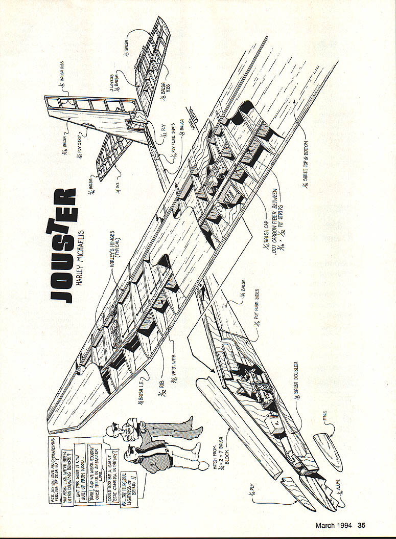
Harley's Hinges (typical)
- 1/8 balsa cap
- 1/8 balsa leading edge
- .007 carbon fiber between 1/16 x 1/8 strips
- 1/16 ply fuse sides
- 1/8 sheet top & bottom
- 1/8 balsa doubler
- Hatch from 3/32 x 3/32 balsa
- 1/4 ply
- 1/8 ply
- Pine and aluminum elements as shown on the plans
Wing
- The airfoil plots provided are for making ribs or for templates for cutting foam-core wings. They are drawn slightly oversize to allow for practical trailing-edge thickness.
- The bottom spar goes in flush with the airfoil bottom. The top spar is capped with soft balsa for shaping. Allow for 1/16 sheeting and 3/32 L.E.
- Tips are 21 inches long and have 1/4-inch washout. Tip cores are cut single taper, trimmed for the break at the L.E., and sanded to a generic airfoil. Keeping the L.E. fairly blunt yields favorable stall characteristics.
- The overall length of the center-section assembly with 1/8 endcaps is 33 1/4 inches. This allows 1/8-inch overlap on each end (assuming a 36-inch sheet of balsa) for tacking the sheeting in place and running the ends of the panel.
- The center core is divided into sections and rejoined by the spar and servo-well structure. Two 18-inch core blanks could be used here, but alignment is critical.
- After cores are cut (allowing for the L.E. wood), draw lines 1/4 inch from each side of the flap hingeline for the first cut. Saw just inside the lines and true up the cut with a long sanding block.
- Cut the walls away to take the spar. Make the front spar cut first, then the rear.
- The plans illustrate typical miniservo well sizes. Servos mount flush to 1/8-inch plywood doublers under the top sheeting, using rails and brackets.
- The flaps' beveled hingeline strips are cut on a table saw (use scrap to determine the bevel). Cut the front strip first, then the shorter rear one. If rubber hinges are used, notch the undersides at the hinge locations with a strip of 50-grit sandpaper glued to a 3/8-inch block.
- For foam-core wings, make 5/8 x 1/2 inch notches in the core at the flap locations for rubber-hinge access openings. Mark the skin and cut 1/2 x 1-1/2 inch openings in the aft skin just ahead of the cleat position; the wing covering will hide these openings.
Skinning
- Satellite City's UFO Thick CyA and Hot Shot accelerator work well for simple, light, and quick skinning. Dave Brown Products' sorghum contact cement is an inexpensive, quick alternative. Only the bottom beads will be needed using these procedures.
- Wick the hingeline strips to the bottom skin. The 1/16-inch plywood extension is flush with the top skin. Bond to the doubler with a coat of quick-curing epoxy; use pressure to maintain good contact until the epoxy sets.
- Cut the skin for a precise fit around the extension and leave some overhang for wicking.
- If using CyA, place the skin in its bed and spray lightly with Hot Shot. Apply a bead of CyA to the core bottom around its perimeter, at the cutouts, and chordwise at three-inch spacing. Keep glue away from the sub-LE and endcaps.
- Press and hold the core in contact with the sheeting using a loose sheet on top to avoid depressions. Mark the pushrod groove on top and cut with a hacksaw blade held against a straightedge.
- Flaps: use a table saw to cut the correct bevel on the inside edge of the TE. Cut the bevel into three-inch sheets for flaps and ailerons. Wick on the rear-beveled/notched strip to make a 2-1/4-inch-wide flap bottom, keeping glue out of the slots and away from the last inboard inch.
- With slots aligned, trim inboard edges to the extension edges. Butt the flaps to the wing, tape them to the work surface, and remove the wing.
- Make the U with the collar on. The front of the wire should be at the hingeline, with the rear ends in the square tubes (placed as far forward as possible). Notch the unglued area of the strip for this, then tack the tubes to the skin and remove the U.
- Place 1/8-inch square strips on each side and cap with 1/32-inch plywood and a wedge. Fit a 2-1/2-inch-wide beveled block to fill underneath the extension and meet the saddle.
- The extension top looks best if covered with lightweight fiberglass cloth and painted. Install the U after the flaps have been hinged.
- Optionally add .007 carbon fiber between the skins at the flap and aileron TEs. Epoxy in place and add the foam flap core or ribs. Cut the top flap sheeting overhang all around, lay it inverted over Saran Wrap, and coat the TE area and core or ribs with quick-curing epoxy. To prevent bow, hold everything flat, wick along the LE, and press until the epoxy sets.
Built-up Wingtip and Foam-Core Tip
- Built-up wingtip: spars are hard 1/8-inch balsa; dihedral braces fit between them with balsa fill. Webs are 1/8-inch hard balsa with vertical grain. The 1/4-inch washout may be built-in or twisted in during covering.
- Foam-core tip: measure 15½ inches out and taper the core so the tip chord is five inches. Make a line 1/8 inch ahead of the aileron hingeline and cut there; also make cutouts for the hinges and DADs. Good sheeting yields ample strength without spars or webs.
- The 1/8-inch plywood dihedral braces are sandwiched between full-depth pieces of 3/32-inch plywood. Use an adhesive that creates unpartable glue joints (quick-drying epoxy works well). CyA makes a brittle joint that can part easily. Add balsa straps to the tops and bottoms of the braces for a good fit into the core. If you do not plan to use ailerons, increase dihedral to 10 degrees.
Beveled / Tapered Hingeline Strips
- The front strip is 1/8 inch; the rear is 3/4 inch. Use 1/2-inch-wide strips to cut the bevel. Pin the strips against a straightedge, then mark and cut the taper. Notch the top for rubber hinges to match cuts in the foam.
Top Skin
- Prepare to attach the top skin by applying CyA or slow CA. Invert the top skin so the core can be positioned, press the ends to tack the skin into position, transfer to the bottom bed, and press to join securely while preserving washout. Wick the top skin to the sub-LE and add the main LE and cleats under the top skin through the openings in the bottom skin.
- Mark the main bolt location on the wing saddle. Make the H unit that secures the wing and epoxy it in place. Add a block of hardwood in front of F2 for the 8-32 bolt. Bolt and align the wing, then drill a pilot hole, tap 8-32, and treat the threads with Zap. Repeat twice. Open the hole in the extension for the bolt shank; the head is recessed into the fairing.
Aileron Core Strip / Ribs
- Trim 3/8 inch from the front edge of the core strip removed for the ailerons so it will fit behind the beveled and tapered strip. For built-up structure, add the rib bits and assemble in the same manner as the flaps.
Rubber Hinges
- Use of rubber hinges is optional but effective for gapless hingelines and avoiding flutter. Cleats anchor the front ends so rubber is free to stretch. Attach cleats with slow CyA and position them with an X-Acto knife. The plans show size and location.
- Some thin CyAs do not cure quickly on this rubber; pink-label Zap works well without accelerator. Use a fine Teflon tube to control application and practice to find out how little to use (and how long parts should be held).
- Hinges are installed first in the covered/glassed fin, flaps, and ailerons. If film covering was used, make slits at the slots and seal inward with a heated tool.
- Cut hinges 1/2 inch wide and two inches long. Mark one end 1/4 inch in, insert 1/4 inch into the fin, flap, and aileron slots, and square up the hinges. Wick a small drop of glue on the inside surfaces only. The fin's hinges should also be glued on only one side to allow replacement.
- The center section can be covered with a 9-1/4-inch-wide piece of material. Apply rearward on the bottom from about 3/8 inch from the hingeline, then go up the hingeline face, around the top, and seal at the extreme LE. Leave a loose flap to overlap the bottom piece later. Bond the loose hinge ends last to the cleats in the wing, before the bottom is covered.
- Tape the flap or aileron to the wing and curl the hinges to insert them. Let gravity dangle the ends under the cleats and use a bent wire to coax shy ones. Invert the wing to attach the front ends of the hinges.
- For ailerons, put CyA on the cleat, use a wax stick to press the slightly-stretched rubber to the top sheeting in front of the cleat for good contact, and leave excess hinge to pull on. For flaps, pull on the hinge, apply Zap, let it go back under slight tension, and pull it upward for a good seal to the cleat.
- It is not necessary for all hinges to be under tension; if overdone, it may tax the servo to reflex the TE.
Spars
- On zoom launches, ordinary spruce spars have failed, so sandwich strips of .007 or .014 carbon fiber between strips of 1/32 ply for the top and bottom spars. Adding 3/8-inch vertical webs between the spars adds strength for high-stress launches—assuming all glue joints are solid.
- Use five-minute epoxy for spar laminations. Glue the dull side of the carbon fiber to one strip, rub with an alcohol-dampened rag, and keep everything in good contact and alignment until the epoxy sets. Sand the shine from the carbon, then add the other strip.
Typical Order of Wing Construction (built-up)
- Bottom sheeting
- Bottom spar
- Ribs and webs
- Sub-LE
- Forward-beveled hingeline strip
- Plywood servo doublers
- Dihedral braces
- Top spar
- Spar cap
- Servos and aileron pushrods
- Top sheeting and LE
- Flaps
For a foam-core wing, assemble the main spar first, make the center-section wood parts, and join the core pieces to them. Otherwise proceed similarly. Pushrod grooves can be made after the bottom sheeting is attached.
Setting Up
- The balance point shown on the plans gives moderate, hands-off dive recovery. I prefer to move the center of gravity rearward and retrim the stab accordingly; the model then zooms faster off the tow, cruises faster, and responds better.
- For starters, set control throws to about 3/8 inch up and down travel at the stab and about 3/8 inch up and 1/8 inch down at the ailerons. You may prefer less at times; use dual rates set low to avoid overcontrol.
- Try one inch of rudder deflection each way if rudder is mixed with ailerons, but use maximum deflection on the separate rudder channel. Adjust the horn bracket on the stud and the clevis location on the flap output arm to get about 90° down travel.
- If your radio has mixing capability, couple rudder and ailerons, mix in down-elevator compensation with flaps, and use camber, TE reflex, and crow landing option.
- For simple radios, use a Y-harness for both aileron servos. A third lead can be wired in to operate the rudder on that channel. Use the throttle channel for flaps, reserving the trim tab to reflex the trailing edge for speed. Manually input elevator compensation with flaps for speed control.
I fly in Mode 2 and use both Standard and Alternate setups. On Standard, throws are set for best handling while cruising. Rather than using preset flaps during launch in Standard, I manipulate the flaps with my thumb on the left-stick cylinder while gripping the transmitter. I avoid options that preclude this independent flap manipulation. Trailing-edge reflex and camber are on the Flight Mode switch, assigned to the left side. I don't use a preset on launch; I prefer to manipulate the flaps as required. If the flaps are reflexed near the top of the launch, zoom speed can be increased for a big chunk of extra altitude.
On Alternate, I have up aileron programmed with down flap for crow to affect sink rate. If the flaps are fully down, switch the ailerons to the selected maximum up throw. Manipulation of the stick gives proportional crow for good sink-rate control on final. Different elevator compensation is required, and more throw is used on all controls.
The Ace MicroPro (with updated software) can be programmed to raise the ailerons at a selectable threshold as flaps are dropped. This preserves independent flap operation for launch and cruise but makes crow available on the same stick.
The fact that the model has flaps doesn't mean you always have to drop them. Doing so just before touchdown is usually fruitless—the plane needs time to slow, and the flight path usually needs correction. Neutralizing lowered flaps just before touchdown will pancake the model and help it stay put.
When flying an aileron-controlled model, I find it useful to apply ailerons, neutralize, pause, and then repeat. This prevents "winding in" from continuously-deflected ailerons. I also find it useful to apply some opposite rudder to flatten the turn. When making left turns, I nudge the side of the stick with the tip of my thumb while gripping the transmitter with the lower part of the thumb. The J2M can be gently turned on rudder for flat thermal turns.
Because of its low fuselage profile, the J2M flies nose hangy-down. Resist the impulse to straighten the model to level flight. Let the model bore in and get up to speed; it will likely fly faster than you expect. To slow the airplane, drop the flaps a bit or camber the trailing edge.
In more than 22 years of continuous experimentation with RC sailplane design, this is the only Two-Meter competition model I liked enough to offer for publication. The J2M and its big brother, the Jouster (July 1993 Model Aviation), have many innovations, fly superbly, and should please most anyone who can do a respectable job of building and trimming. I hope you enjoy this smaller, highly maneuverable version of the Jouster as much as I have.
2-Meter Jouster (specifications)
- Type: RC sailplane
- Wingspan: 78-1/2 inches
- Flying weight: 38–40 ounces
- Number of channels: Four
- Construction: Built-up or foam core
- Covering/finish: Iron-on film, fiberglass
Transcribed from original scans by AI. Minor OCR errors may remain.

