
Jumbo Scale: Douglas 0-38
This large rubber-powered version of one of the Army Air Corps bipes is an exceptional flier.
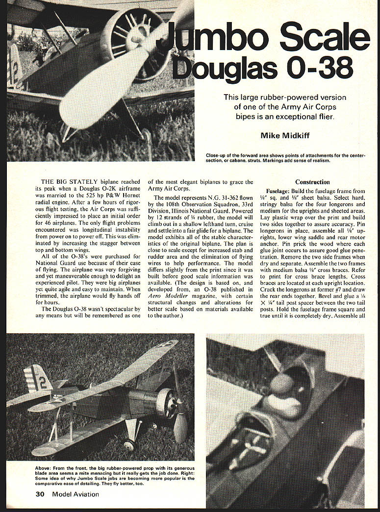
Mike Midkiff
THE BIG STATELY biplane reached its peak when a Douglas O-2K airframe was married to the 525 hp P&W Hornet radial engine. After a few hours of rigorous flight testing, the Air Corps was sufficiently impressed to place an initial order for 46 airplanes. The only flight problems encountered was longitudinal instability from power on to power off. This was eliminated by increasing the stagger between top and bottom wings.
All of the O-38's were purchased for National Guard use because of their ease of flying. The airplane was very forgiving and yet maneuverable enough to delight an experienced pilot. They were big airplanes yet quite agile and easy to maintain. When trimmed, the airplane would fly hands off for hours.
The Douglas O-38 wasn't spectacular by any means but will be remembered as one of the most elegant biplanes to grace the Army Air Corps.
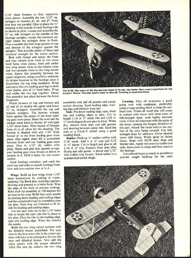
The model represents N.G. 31-362 flown by the 108th Observation Squadron, 33rd Division, Illinois National Guard. Powered by 12 strands of 1/4" rubber, the model will climb out in a shallow lefthand turn, cruise and settle into a fair glide for a biplane. The model exhibits all of the stable characteristics of the original biplane. The plan is close to scale except for increased stab and rudder area and the elimination of flying wires to help performance. The model differs slightly from the print since it was built before good scale information was available. (The design is based on, and developed from, an O-38 published in Aero Modeller magazine, with certain structural changes and alterations for better scale based on materials available to the author.)
Construction
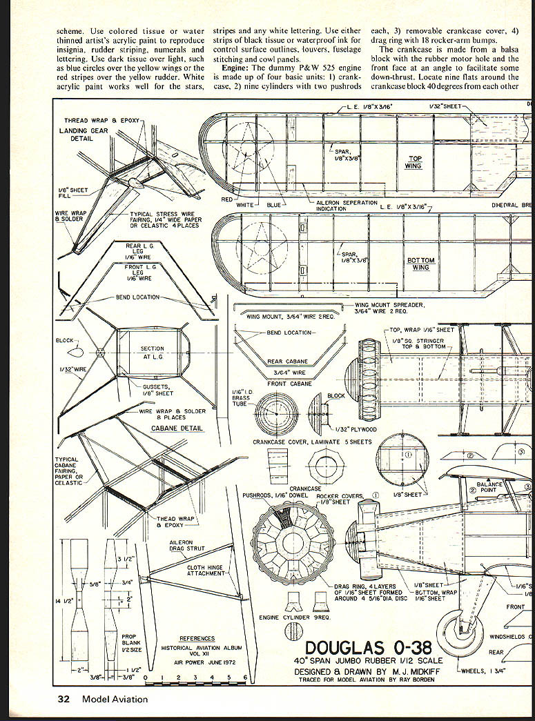
Fuselage: Build the fuselage frame from 1/8" sq. and 1/16" sheet balsa. Select hard, stringy balsa for the four longerons and medium for the uprights and sheeted areas. Lay plastic wrap over the print and build two sides together to assure accuracy. Pin longerons in place, assemble all 1/8" uprights, lower wing saddle and rear motor anchor. Pin-prick the wood where each glue joint occurs to assure good glue penetration. Remove the two side frames when dry and separate. Assemble the two frames with medium balsa 1/8" cross braces. Refer to print for cross brace lengths. Cross braces are located at each upright location. Crack the longerons at former #7 and draw the rear ends together. Bevel and glue a 1/8" x 1/4" tail post spacer between the two tail posts. Hold the fuselage frame square and true until it is completely dry.
Assemble all formers and 1/16" sheet formers and respective cross pieces. Assemble two 3/32" sq. stringers at formers #5, #6 and #7. Note: run parallel. Glue and place 1/8" sheeting outside fuselage side as shown on print. Locate and assemble 1/8" sq. side stringers outside fuselage uprights except rearmost upright stringers which draw flush. Now assemble four large gussets top and bottom against the stringers and uprights; this provides plenty of shear and torsional strength for the motor anchor.
Bind, thread and epoxy front and rear cabane strut wires to two hard balsa cross pieces. Bind and solder two wing mount wires to the cabane wires and two spreader wires to the wing mount wires. Epoxy the assembly between the upper longerons, being careful to maintain its proper location on the fuselage since it determines top wing incidence.
Wrap and epoxy two landing gear legs to cross pieces of 1/8" hard balsa. Wrap and solder the two legs together. Epoxy the assembly in place between the lower longerons. Notch formers #1 (top and bottom) and #2 to receive upper and lower 1/8" sq. stringers. Assemble top and bottom stringers; the bottom stringer butts against the center front landing gear cross piece.
Sheet the cowl and cockpit areas back to former #5 with light 1/16" sheet balsa. Note layout formers #1 through #5 allow sheeting. Bottom is sheeted with soft 1/16". Former #1 front landing gear cross piece and 1/8" sheet fill are assembled between front and rear landing gear cross pieces. Glue 1/32" ply rudder trim plate. Make and glue four gussets to support landing gear cross braces as shown in section A-A. Drill 5/32" rear motor anchor. Sand fuselage complete; sand cowl top and sides to match fuselage front view (see cross section view A-A).
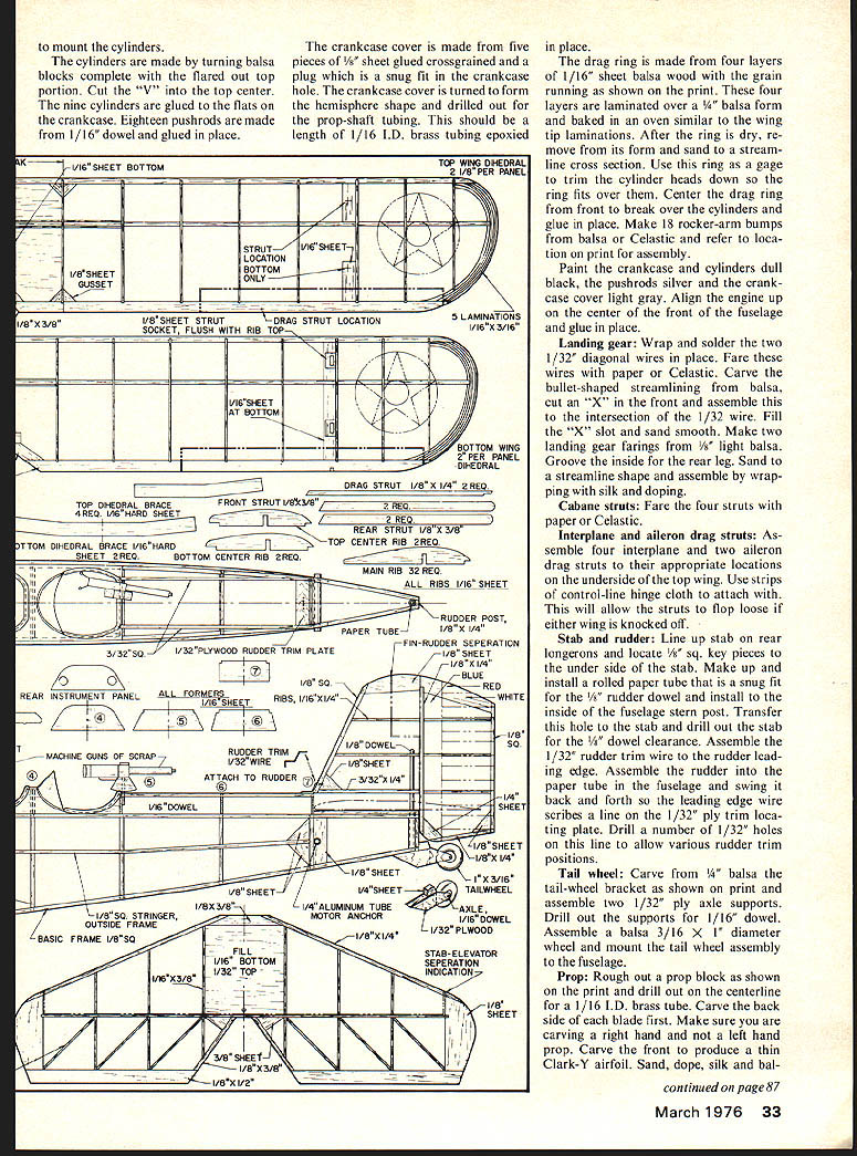
Wings: Build up four wing panels from 1/16" sheet laminations, soaking in water and applying Tite-Bond glue, stacking together and pinning on a balsa form. Wax the edge form to prevent sticking. Bake tip assemblies at 150°F for 1 hour in the oven. Build four outer panels pinning down leading and trailing edges. Use the spar slots cut in the 1/16" balsa ribs to locate the spar; pin this in place to the plan. Glue the ribs to the leading edge, spar and trailing edge. When dry, remove the panels.
Build the two wing center sections with the dihedral braces assembled. The spar slots in the four outer ribs in the center sections will have to be enlarged to fit over the spar and dihedral braces. Now add the outer panels with the proper dihedral. After this is set up, remove the two wing assemblies and add all gussets and center section sheeting. Sand leading edge, trailing edge and blend in wing tips.
Stab: Pin down leading edge, spar, sheet tips and trailing edges to plan. Cut to length 1/16" x 3/16" stock ribs and 1/16" x 1/8" stock diagonals and glue in place. When dry, remove from plan and add gussets and sheeting between center ribs. Sand the stab to a Clark-Y airfoil using a good sanding block.
Rudder: Pack up 1/8" rudder outline with 1/16" stock. Add 1/8" x 1/4" spar and 3/32" x 1/4" pieces. Cut to length and glue in all 1/16" x 1/4" ribs. Remove from plan after drying and add gusset, dowel and 1/32" wire rudder trim locator. Sand rudder to a symmetrical airfoil shape.
Covering: Give all structures a good going over with sandpaper, preferably using a large sanding block to keep the surfaces true. Prime all wood that will come in contact with tissue with thinned coats of full-strength dope, sand lightly between coats. Cover all structures with the grain of the tissue running the longest direction of the part. Attach the tissue only to the outline of the area being covered. Use full-strength dope for adhesives. Cover sheeted areas with tissue. Water-spray to shrink tissue. Dope with 50/50 clear dope and thinner mix. Apply two coats to rudder and stab, three coats to wings and four coats to the fuselage.
Use colored tissue as much as possible to prevent weight build-up for the color markings. Use either thinned artist's acrylic paint to reproduce insignia, rudder striping, numerals and lettering. Use dark tissue over light, such as blue circles over the yellow wings or the red stripes over the yellow rudder. White acrylic paint works well for the stars, stripes and any white lettering. Use either strips of black tissue or waterproof ink for control surface outlines, louvers, fuselage stitching and cowl panels.
Engine
The dummy P&W 525 engine is made up of four basic units: 1) crankcase, 2) nine cylinders with two pushrods each, 3) removable crankcase cover, 4) drag ring with 18 rocker-arm bumps.
The crankcase is made from a balsa block with the rubber motor hole and the front face at an angle to facilitate some down-thrust. Locate nine flats around the crankcase block 40 degrees from each other.
Crankcase cover: laminate 5 sheets. The crankcase cover is made from five pieces of 1/8" sheet glued crossgrained and a plug which is a snug fit in the crankcase hole. The crankcase cover is turned to form the hemisphere shape and drilled out for the prop-shaft tubing. This should be a length of 1/16" I.D. brass tubing epoxied in place.
The drag ring is made from four layers of 1/16" sheet balsa wood with the grain running as shown on the print. These four layers are laminated over a 1/4" balsa form and baked in an oven similar to the wing tip laminations. After the ring is dry, remove from its form and sand to a streamline cross section. Use this ring as a gage to trim the cylinder heads down so the ring fits over them. Center the drag ring from front to back over the cylinders and glue in place. Make 18 rocker-arm bumps from balsa or Celastic and refer to location on print for assembly.
Paint the crankcase and cylinders dull black, the pushrods silver and the crankcase cover light gray. Align the engine up on the center of the front of the fuselage and glue in place.
Landing gear: Wrap and solder the two 1/32" diagonal wires in place. Fair these wires with paper or Celastic. Carve the bullet-shaped streamlining from balsa, cut an "X" in the front and assemble this to the intersection of the 1/32" wire. Fill the "X" slot and sand smooth. Make two landing gear fairings from 1/8" light balsa. Groove the inside for the rear leg. Sand to a streamline shape and assemble by wrapping with silk and doping.
Cabane struts: Fair the four struts with paper or Celastic.
Interplane and aileron drag struts: Assemble four interplane and two aileron drag struts to their appropriate locations on the underside of the top wing. Use strips of control-line hinge cloth to attach with. This will allow the struts to flop loose if either wing is knocked off.
Stab and rudder: Line up stab on rear longerons and locate 1/8" sq. key pieces to the underside of the stab. Make up and install a rolled paper tube that is a snug fit for the 1/8" rudder dowel and install to the inside of the fuselage stern post. Transfer this hole to the stab and drill out the stab for the 1/8" dowel clearance. Assemble the 1/32" rudder trim wire to the rudder leading edge. Assemble the rudder into the paper tube in the fuselage and swing it back and forth so the leading edge wire scribes a line on the 1/32" ply trim locating plate. Drill a number of 1/32" holes on this line to allow various rudder trim positions.
Tail wheel: Carve from 1/4" balsa the tail-wheel bracket as shown on print and assemble to 1/32" ply axle supports. Drill out the supports for 1/16" dowel. Assemble a balsa 3/16" x 1/0" diameter wheel and mount the tail wheel assembly to the fuselage.
Prop: Rough out a prop block as shown on the print and drill out on the centerline for a 1/16" I.D. brass tube. Carve the back side of each blade first. Make sure you are carving a right hand and not a left hand prop. Carve the front to produce a thin Clark-Y airfoil. Sand, dope, silk and bal- ance, install a free wheeler and make a prop shaft. Assemble prop, thrust bearings and crankcase cover nose button to the prop shaft.
Assembly: Assemble top and bottom wings with rubber bands. Check that the wings are parallel to each other, front to back. If not, shim between bottom wing and bottom wing saddle to achieve same. Assemble stab to its location holding in place with rubber bands hooked around tail wheel bracket and motor anchor tube. Assemble rudder through stab into the paper tube, line up straight and position 1/32" wire in the nearest trim hole in the 1/32" ply plate.
Flying: Make up a motor of 12 strands from 1/4" rubber of approximately 36 in. long. Install the motor ballast to achieve center of gravity as shown. Hand glide the ship. If you have to move the CG more than a 1/2" one way or the other to prevent a stall or dive, relocate the CG to the original location and shim up the front of the stab to cure a stall or the back to cure a dive.
Test with low winds to achieve a straight-out powered glide. Add more winds and just enough down-thrust to prevent a severe stall. Add more winds and trim with either side-thrust or slight rudder off-set to achieve a wide lefthand climbing turn. The turning should eliminate any slight stalling that may have been present. If you attempt to fly power to the right, be careful. Mine had a tendency to wind in to the right under maximum winds. So I suggest either a left-right or a right-left pattern.
If you have the fortune to fly in an area with closely clipped grass, those large wheels will allow a beautiful landing and roll-out. That sight alone makes building the O-38 worthwhile.
Suggested Color Schemes —
1) Fuselage: olive drab. Wings and tail group: chrome yellow. Drag ring, struts and landing gear: light gray.
2) Fuselage, struts, landing gear and drag ring: blue.
3) Fuselage and drag ring: dark blue. Top of wings and tail group: chrome yellow. Bottom of wings and landing gear: silver. All lettering and numbering: white or black.
Transcribed from original scans by AI. Minor OCR errors may remain.

