
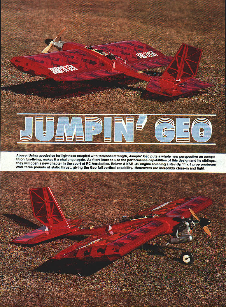
JUMPIN' GEO
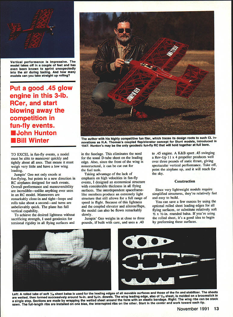
Above: Using geodesics for lightness coupled with torsional strength, Jumpin' Geo puts a whole new perspective on competition fun-flying and makes it a challenge again. Maneuvers are incredibly close-in and tight; as fliers learn to use the performance capabilities of this design and its siblings, they will open a new chapter in the sport of RC aerobatics. A K&B .45 engine spinning a Rev‑Up 11×4 prop produces over three pounds of static thrust, giving the Geo full vertical capability.
To excel in fun-fly events, a model must be able to maneuver quickly and tightly about all axes. That means it must weigh very little and have low wing loading. Jumpin' Geo not only excels at fun-flying, it points to a new direction in RC airplanes designed for such events. Overall performance and maneuverability are incredible—unlike anything ever seen in an RC model. Loops and rolls take about a second, turns are unbelievably quick, and the plane has full vertical capability.
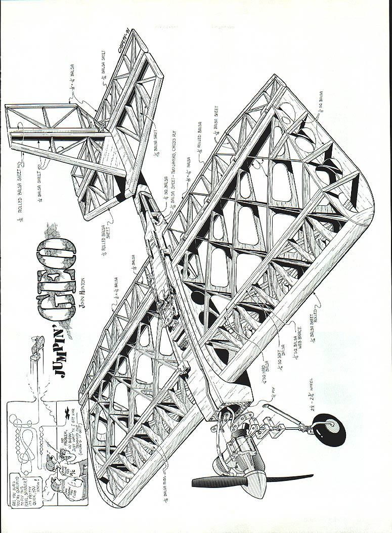
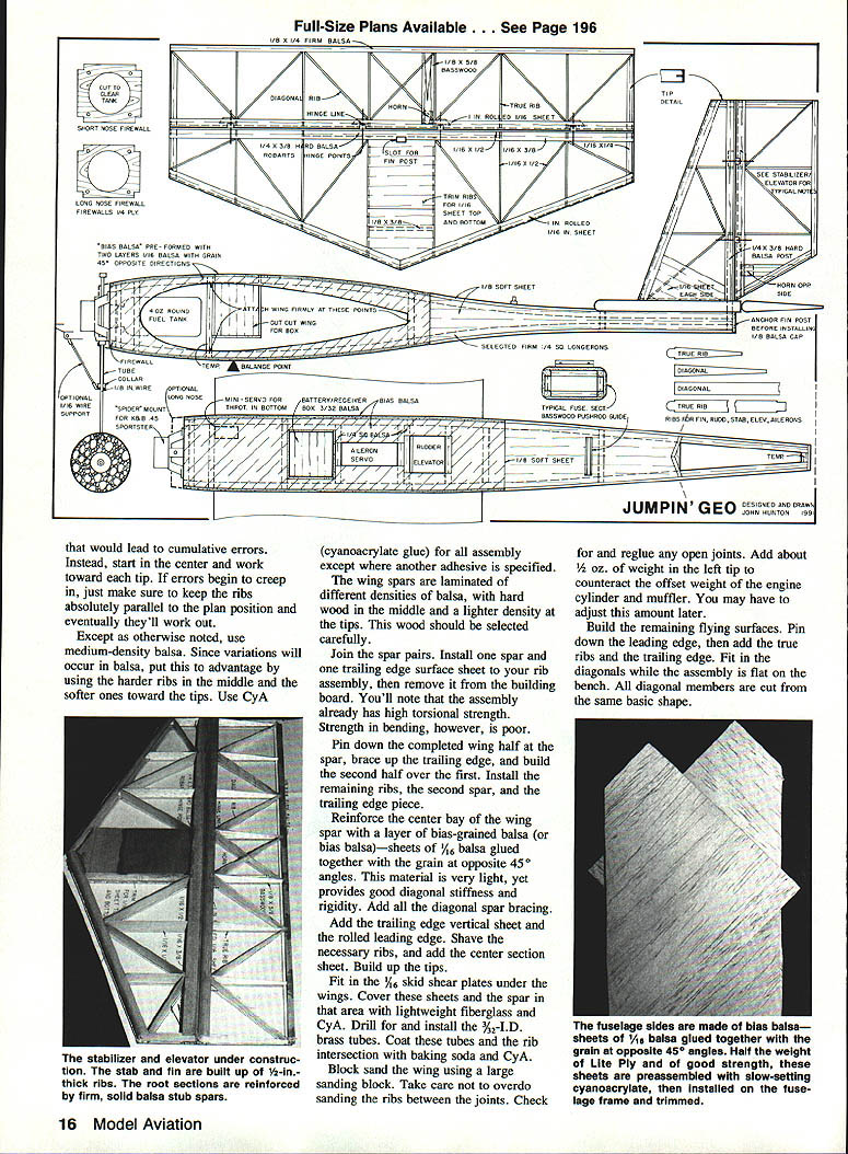
To achieve the desired lightness without sacrificing strength, geodesic construction is used for torsional rigidity in all flying surfaces and the fuselage. This eliminates the need for the usual D‑tube sheeted leading edge. Since the front of the wing is nonstructural, the front area can be used to accommodate the fuel tank.
Taking advantage of the lack of emphasis on high velocities in fun-fly events, the design uses an economical structure with considerable thickness in the flying surfaces. Interdependent, spaceframe‑like members produce an extremely light structure that still allows a full range of speeds in flight. Because of this lightness and the large coupled elevator and aileron/flap surfaces, the model can also be flown remarkably slowly.
Jumpin' Geo weighs close to three pounds when built carefully and uses a .40–.45 engine. A K&B Sport .45 swinging a Rev‑Up 11×4 propeller produces well over three pounds static thrust, giving spectacular vertical performance—take off, point the airplane up, and it will reach the sky.
Construction
Since very lightweight models require simplified structures, they're relatively fast and easy to build. You can save a few ounces by using optional rolled‑sheet leading edges for all flying surfaces, or substitute relatively soft 3/32" × 1/2" rounded balsa. If you're using rolled sheet, preform these surfaces before final assembly.
Special construction features
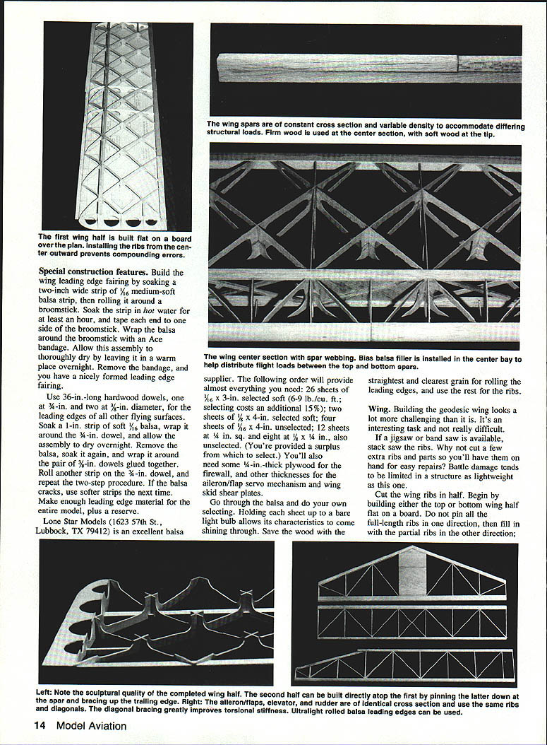
- Build the wing leading‑edge fairing by soaking a two‑inch‑wide strip of 1/16" medium‑soft balsa, then rolling it around a broomstick. Soak the strip in hot water for at least an hour and tape each end to the broomstick. Wrap the balsa around the broomstick with an Ace bandage and allow the assembly to dry in a warm place overnight. Remove the bandage to reveal a nicely formed leading‑edge fairing.
- Use 36‑in. hardwood dowels for rolled leading edges and other flying‑surface members: one dowel at 3/8‑in. diameter and two at 3/16‑in. diameter. Soak a 1‑in. strip of soft 3/32" balsa, wrap it around the 3/8‑in. dowel, and dry overnight. Remove, soak again, and wrap around the pair of 3/16‑in. dowels glued together. Repeat as needed to produce enough leading‑edge material for the entire model plus a reserve. If the balsa cracks, use softer strips next time.
Lone Star Models (1623 57th St., Lubbock, TX 79412) is an excellent balsa supplier. The following order will provide almost everything you need:
- 26 sheets of 1/16" × 3" selected soft (6–9 lb/cu ft) — selecting costs an additional 15%
- 2 sheets of 1/8" × 4" selected soft
- 4 sheets of 3/16" × 4" unselected
- 12 sheets of 1/8" × 4" unselected
- 12 sheets of 1/4" × 4" unselected
- 8 sheets of 1/8" × 1/4" unselected
You will also need some 1/8"‑thick plywood for the firewall and other thicknesses for the aileron/flap servo mechanism and wing skid shear plates. Go through the balsa and select your own stock—hold each sheet up to a bare light bulb to judge grain and flaws. Save the straightest, clearest‑grain sheets for rolling leading edges and use the rest for ribs.
Wing
Building the geodesic wing looks more challenging than it is. If a jigsaw or band saw is available, stack‑saw the ribs. Cut a few extra ribs and parts for repairs—battle damage tends to be limited in such a lightweight structure.
- Cut the wing ribs in half (for top and bottom halves). Build either the top or bottom wing half flat on a board, working in small sections and installing ribs from the center outward to prevent compounding errors. Do not pin all full‑length ribs in one direction and then fill in with partial ribs; instead, work symmetrically from the center.
- Build the center section with spar webbing and install bias balsa filler in the center bay to help distribute flight loads between the top and bottom spars. Use the straightest, clearest‑grain stock for center bay webbing; outer panels may use softer wood.
- When assembling the geodesic lattice, glue intersections carefully and allow ample drying time before removing pins. The diagonal bracing greatly improves torsional stiffness and gives the completed wing a sculptural quality.
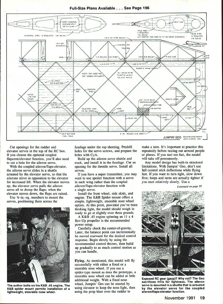
- Finish each wing half, join them at the center with appropriate sheeting and shear plates, trim, sand, and install the aileron/flap servo mechanism.
- The ailerons/flaps, elevator, and rudder use identical cross sections and the same ribs and diagonals. Ultralight rolled balsa leading edges can be used.
- Add a 1/16" skid shear plate under the wings. Cover shear plates and the spar area with lightweight fiberglass and CyA (cyanoacrylate). Drill for and install 3/32" I.D. brass tubes where noted. Coat tubes and rib intersections with baking soda and CyA to form strong fillets.
- Block sand the wing with a large sanding block, taking care not to over‑sand ribs between joints. Re‑glue any open joints.
- Add about 1/2 oz of weight in the left tip to counteract engine and muffler offset; adjust later as needed.
Notes on ribs and spars:
- Use medium‑density balsa for most parts. Put variations in balsa to advantage: reserve the harder ribs for the middle and use softer ribs toward the tips.
- Use CyA glue for assembly except where another adhesive is specified.
- Wing spars are laminated of different densities of balsa, with hardwood in the middle and lighter density at the tips—select this wood carefully.
- Reinforce the center bay of the wing spar with bias‑grained balsa (sheets of 1/16" balsa glued with grain at opposite 45° angles) for light diagonal stiffness.
Tip construction and washout:
- Build the tips flat on the bench. Sand the top surfaces to the proper thickness, then align these surfaces with the rest of the structure. The bottom surfaces of the tips will sweep upward, appearing warped; place the flat area at the top and the swept area at the bottom. This produces tapered tips and introduces washout in the upright wing, improving stall characteristics.
- All diagonal members are cut from the same basic shape. The only complicating factor is sanding the aileron/flap tips to match the wing tips.
Stabilizer and rudder:
- Build the stabilizer and rudder with 1/16"‑deep ribs and diagonals.
Fuselage
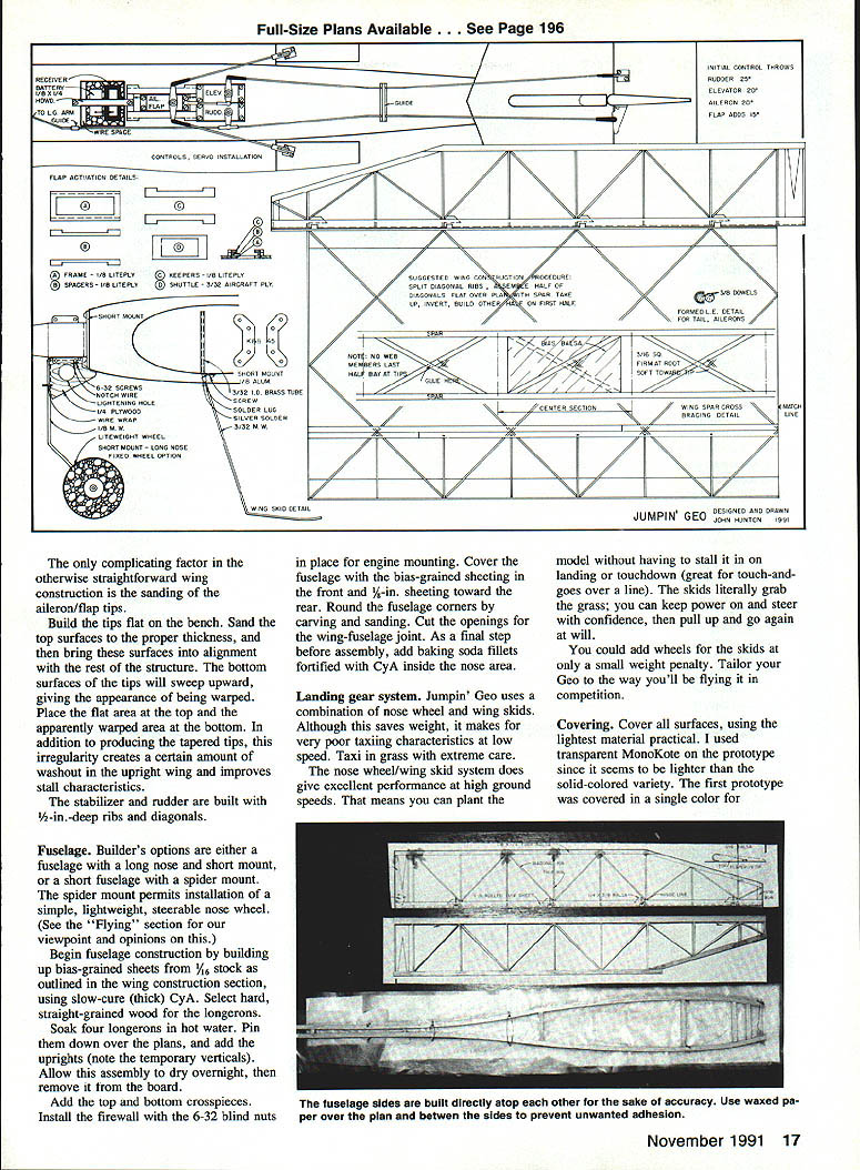
Builder's options: a full fuselage with a long nose and short mount, or a short fuselage with a spider mount. The spider mount permits installation of a simple, lightweight, steerable nose wheel.
- Begin fuselage construction by building bias‑grained sheets from 1/16" stock as outlined in the wing section, using slow‑cure (thick) CyA. Select hard, straight‑grained wood for the longerons.
- Soak four longerons in hot water, pin them over the plans, and add the uprights (note temporary verticals). Allow assembly to dry overnight before removing from the board.
- Add top and bottom crosspieces. Install the firewall with 6‑32 blind nuts in place for engine mounting.
- Cover the fuselage front with bias‑grained sheeting and the rear with 1/16" sheeting. Round corners by carving and sanding. Cut openings for the wing‑fuselage joint.
- As a final step before assembly, add baking soda fillets fortified with CyA inside the nose area.
Landing gear system
Jumpin' Geo uses a combination of nose wheel and wing skids. This saves weight but results in poor low‑speed taxiing characteristics—taxi in grass with extreme care. The nose wheel/wing skid system gives excellent performance at high ground speeds: the skids grab the grass so you can keep power on, steer with confidence, then pull up and go again for touch‑and‑go operations.
You can add wheels for the skids for only a small weight penalty. Tailor your Geo to how you will fly it in competition. The K&B Spider mount is a simple, lightweight, steerable nose wheel option.
Covering
- Cover all surfaces using the lightest material practical. Transparent MonoKote was used on the prototype since it seems lighter than solid colors. The second prototype used Micafilm, which is even lighter.
- For easy orientation, put large identifying color swatches on the top and bottom or cover top and bottom in different colors.
- Cut covering material to match mating surfaces and assemble all parts.
- Use baking soda fillets and CyA at critical areas such as wing and stabilizer installations.
- Since the wing is not removable, do not hinge the ailerons until wing installation is complete. Complete all hinge installations with epoxy and install control horns.
Final assembly
- Install a round four‑ounce fuel tank in the front fuselage/wing area. Cut a disc from the plastic top of a margarine container to cover the fuel tank hole in the firewall; drill the disc for engine mount holes and fuel lines. Seal the plastic to the firewall with silicone sealant.
- Install the radio control gear directly through the top of the fuselage. Linkages are exposed (not routed into the fuselage interior).
- Stack the receiver and battery, wrap with thin foam, and measure this assembly to size the RC box. Build the RC box from 3/32" balsa and cut an opening in the fuselage top sheeting just behind the wing spar.
- Cut openings in the top of the RC box for the rudder and elevator servos. If using the optional coupled aileron/flap–elevator function, cut a hole for the aileron servo as well.
- Mount servos on 1/4"‑square members across the fuselage under the top sheeting. Predrill and prepare holes with CyA.
- Build the aileron servo shuttle and track; install in the fuselage. Cut an opening for the throttle servo and install all servos.
- The coupled aileron/flaps–elevator option: the aileron servo slides in a shuttle actuated by the elevator servo so that the ailerons move in opposition to the elevator for increased lift. When the elevator moves up, the elevator servo pulls the aileron servo aft to droop the flaps; when the elevator moves down, the flaps are raised.
- If you have a super transmitter, you may prefer spoiler function with a servo at each wing instead of the coupled single‑servo system.
- Install the front wheel, side skids, and spinner.
If built with attention to weight, the ready‑to‑go model should weigh slightly over three pounds. The recommended power setup is a K&B .45 engine spinning an 11×4 Rev‑Up propeller.
Carefully check the center of gravity. You may move the balance point rearward incrementally for desired control response. Begin flying slowly with recommended control throws and gradually increase to the amount of control you can handle.
Flying
- The model will taxi and fly with either a fixed or steerable nose wheel. With a fixed nose wheel, steer on the ground by using elevator to keep the nose light and using prop blast over the rudder to turn. Practice this before taxiing near people or other planes; taxi too fast and the model will take off prematurely.
- Do not use full control stick deflections while flying fast—this model has structural limitations. If you want to turn tight, slow down first; loops and turns are actually tighter if started slowly.
- Use a four‑pitch prop to keep airspeed down and vertical capability up. Models that turn this tightly produce considerable G‑forces at high speed, so use good judgment.
- Although many fun‑fly models use smaller engines (for example, an O.S. .32), Jumpin' Geo uses up to .45 power while still staying near the three‑pound target.
- The Geo flies slowly and tightly, yet penetrates wind well. It bridges the gap between traditional "Ugly Stick" types and more delicate new‑generation models.
As fliers learn to use the capabilities of Jumpin' Geo and its siblings, they will open a new chapter in RC aerobatics. At its first contest—the FARM fun fly near Warrenton, Virginia—Jumpin' Geo placed first in time for takeoff and climb for a 15‑second spot landing, first in Fast‑Slow, and first in takeoff and number of loops in 30 seconds. The Geo is unlikely to excel in a beauty contest, but otherwise it's probably unmatched.
Build one for yourself—and enjoy.
For additional specialized fun‑fly designs, see Jerry Smith's built‑up design (RC Report, December 1990) and Dan Stevens's hollowed‑foam wing design (RC Report, February 1991).
Transcribed from original scans by AI. Minor OCR errors may remain.

