
KA-10
Tom Dixon
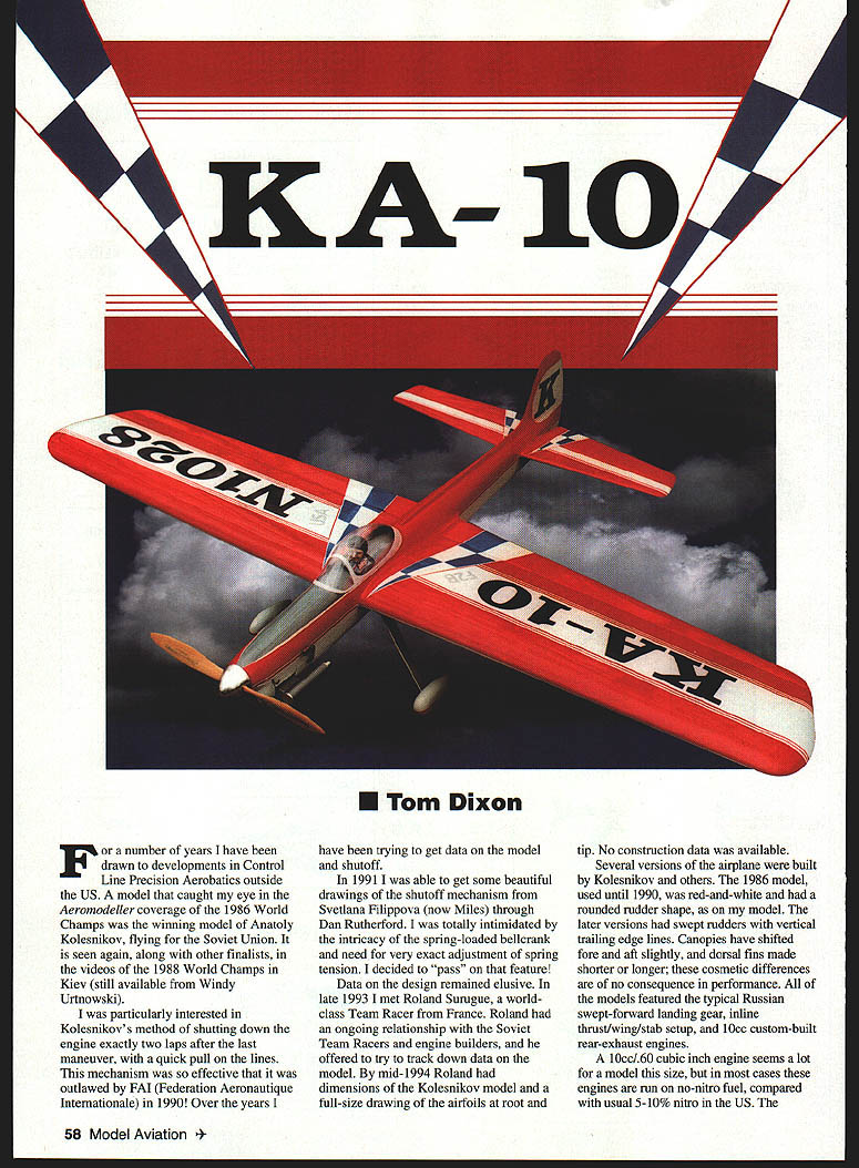
For a number of years I have been drawn to developments in Control Line Precision Aerobatics outside the US. A model that caught my eye in the Aeromodeller coverage of the 1986 World Champs was the winning model of Anatoly Kolesnikov, flying for the Soviet Union. It is seen again, along with other finalists, in the videos of the 1988 World Champs in Kiev (still available from Windy Urtnowski).
I was particularly interested in Kolesnikov's method of shutting down the engine exactly two laps after the last maneuver, with a quick pull on the lines. This mechanism was so effective that it was outlawed by the FAI (Federation Aeronautique Internationale) in 1990. Over the years I have been trying to get data on the model and shutoff.
In 1991 I obtained detailed drawings of the shutoff mechanism from Svetlana Filippova (now Miles) through Dan Rutherford. I was intimidated by the intricacy of the spring-loaded bellcrank and the need for very exact spring-tension adjustment, so I decided to omit that feature. In late 1993 I met Roland Surugue, a world-class Team Racer from France, who had contacts with the Soviet Team Racers and engine builders. By mid-1994 Roland had dimensions of the Kolesnikov model and a full-size drawing of the airfoils at root and tip. No construction data was available.
Several versions of the airplane were built by Kolesnikov and others. The 1986 model, used until 1990, was red-and-white and had a rounded rudder shape, as on my model. Later versions have swept rudders with vertical trailing edges. Canopies have shifted fore and aft slightly, and dorsal fins made shorter or longer; these cosmetic differences are of no consequence in performance. All of the models featured the typical Russian swept-forward landing gear, inline thrust/wing/stab setup, and 10cc custom-built rear-exhaust engines.
A 10 cc (0.60 cu in) engine seems a lot for a model of this size, but in most cases these engines are run on no-nitro fuel, compared with the usual 5–10% nitro in the US. The KA-10 specifications called for a 340 mm diameter x 14 mm pitch prop (13 3/8 x 5 1/2 inches). Such a large prop tends to limit peak engine output somewhat and helps ensure a constant maneuvering speed. With a large engine being used as a power brake, Kolesnikov's model was especially light—about 1,700 grams (59 1/2 ounces). That's fairly high loading for a 640-square-inch wing.
With a smaller engine, performance would suffer; the 10 cc engine and large prop provide plenty of power to keep the wing working. I was astonished to find the airplane had differential flaps: the inboard flap moves slightly to create a rolling force and aid line tension. Most people abandoned differential flaps about 1961, because the outward-roll setup creates an offset and consequent inward yaw. There are also difficulties getting the tip weight correct to achieve clean square maneuvers.
The airplane is built with the customary single flap horn. Nose moment is fairly long by US standards because the hand-built rear-exhaust engine weighs about 12 ounces complete with silencer; the silencer weight is distributed somewhat rearward. A shorter nose would require excess ballast; a heavier engine can result in a shorter nose. The airplane uses Vorobiev engines — the 60 ST and the 50, the latter having the nose about 1/2 inch shorter.
The KA-10 design is presented as a tribute to World Champion Anatoly Kolesnikov, who was also European Champion on several occasions. I don't know for sure if KA-10 is the accurate name of Kolesnikov's airplanes. The large letters KA-10 on the bottom wing presumably stand for Kolesnikov Aerobat 10cc.
Construction
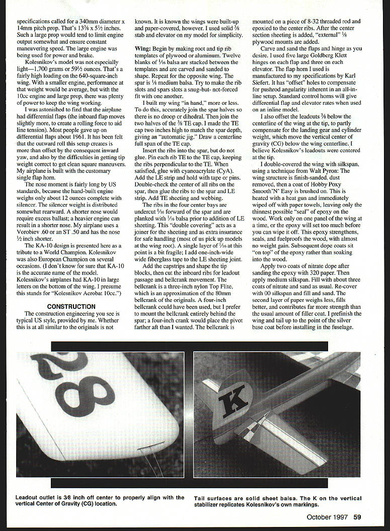
Construction and engineering follow typical US practice; full-size drawings are provided. Whether the original models were identical is not known. The original wings were built-up and paper-covered; for simplicity I used a solid 3/32" stabilizer and elevator on my model.
Wing
- Make root and tip rib templates from plywood or aluminum.
- Stack twelve blanks of 1/8" balsa between the templates, carve and sand to shape. Repeat for the opposite wing.
- Spars are 1/8" medium balsa. Make rib and spar slots a snug-but-not-forced fit.
- I built the wing "in hand." Accurately join the spar halves so there is no droop or dihedral, then join the two halves of the 3/8" trailing-edge (TE) cap. I made the TE cap two inches high to match the spar depth, creating an "automatic jig." Draw a centerline full span on the TE cap.
- Insert ribs into the spar (do not glue initially). Pin each rib to the TE cap, keeping the ribs perpendicular. When satisfied, glue with cyanoacrylate (CyA).
- Add the leading-edge (LE) strip and hold with tape or pins. Double-check the center ribs and spar, then glue the ribs to the spar and LE strip.
- Add TE sheeting and webbing. The ribs in the four center bays are undercut 1/16" forward of the spar and are planked with 1/16" balsa prior to the LE sheeting. This double covering acts as joiner sheeting and provides extra insurance for safe handling (many pick up models by the wing root). I add one-inch-wide fiberglass tape at the LE sheeting joint for reinforcement.
- Add capstrips and shape the tip blocks, then cut the inboard ribs for leadout passage and bellcrank movement.
- The bellcrank I used is a three-inch Nylon Top Flite, an approximation of the 60 mm bellcrank of the originals. A four-inch bellcrank could have been used, but I preferred to mount the bellcrank entirely behind the spar. The bellcrank is mounted on 8-32 threaded rod and epoxied to the center ribs. After the center section sheeting is added, external 1/8" plywood mounts are added.
- Carve and sand flaps and hinges as desired. I used five large Goldberg Klett hinges on each flap and three on each elevator. The flap horn I used was manufactured to my specifications by Karl Seifert; it has offset holes to compensate for pushrod angularity inherent in an all-inline setup. Standard control horns will give differential flap and elevator rates when used on an inline model.
- I offset the leadouts 3/8" below the wing centerline at the tip to partly compensate for the landing gear and cylinder weight, which move the vertical center of gravity below the wing centerline. I believe Kolesnikov's leadouts were centered at the tip.
- Covering: I double-covered the wing with silkspan, using a technique from Walt Pyron. Finish-sand the structure, then dope and prime. Brush on a coat of Hobby Poxy Smooth-N-Easy, heat with a heat gun and immediately wipe off with paper towels to leave a very thin epoxy seal on the wood. Work one panel at a time so the epoxy can be wiped off before it sets. The epoxy strengthens, seals, and waterproofs the wood with minimal weight gain. Sand with 320 paper, then apply two coats of nitrate dope and the medium silkspan. Fill with about three coats of nitrate and sand as usual. The second layer of paper weighs less, fills better, and contributes far more strength than the usual amount of filler coat. I prefinish the wing and tail up to the silver base coat before installing in the fuselage.
Fuselage
- Cut formers to match the width of the engine you will use. Epoxy the formers, maple mounts, and cross-grained 1/2" balsa together to form an accurate crutch. Drill engine mounting holes and install blind nuts.
- Laminate 1/2" plywood fuselage doublers to the sides with slow-cure epoxy. Epoxy the engine crutch first to one side, then to the other, keeping everything square.
- Do not cut out the wing and stab openings until the fuselage is roughed out. Make a template of the root rib and trace the shape on the fuselage sides with a ball-point pen.
- Tack-glue top and bottom blocks and cowl in place, carve and sand to shape, then remove and hollow to 1/8" thickness.
- Install wing and stab by cutting the fuselage sides at the top, then replace the cutouts (with doublers behind the cuts) after installation. Install the landing gear platform and tail wheel mount just prior to final installation of the bottom block.
- My model's fuselage is covered with 0.56-ounce glass cloth, applied with Hobby Poxy Smooth-N-Easy.
Landing Gear
- The plan shows 5/32" wire landing gear. A custom 1/8" aluminum version is available from BJ's Mfg., or a carbon-fiber version is available from the author.
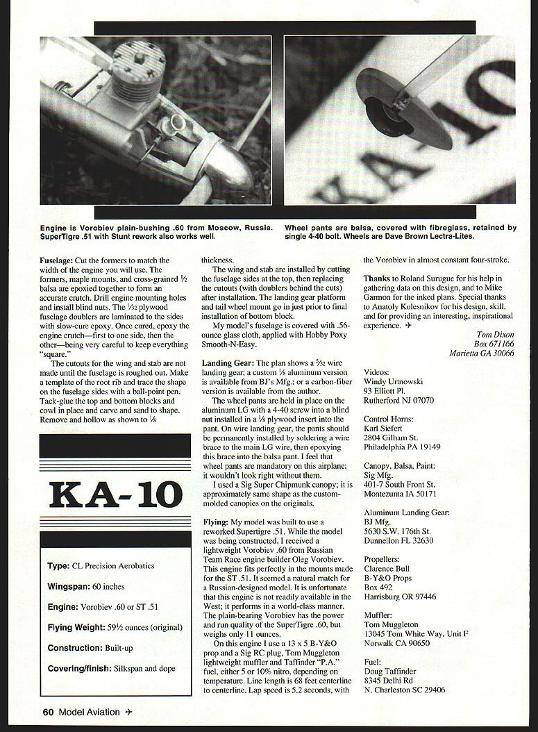
- Wheel pants: On aluminum LG, the pants are held with a 4-40 screw into a blind nut installed in a 1/8" plywood insert in the pant. On wire landing gear, pants should be permanently installed by soldering a wire brace to the main LG wire and epoxying this brace into the balsa pant. Wheel pants are mandatory for appearance on this airplane.
- Canopy: I used a Sig Super Chipmunk canopy; it approximates the custom-molded canopies used on the originals.
Specifications
- Type: CL Precision Aerobatics
- Wingspan: 60 inches
- Engine: Vorobiev .60 or ST .51 (or Vorobiev 50)
- Flying weight: 59 1/2 ounces (original)
- Construction: Built-up
- Covering/finish: Silkspan and dope
Flying
My model was built to use a reworked SuperTigre .51. During construction I received a lightweight Vorobiev .60 from Russian Team Race engine builder Oleg Vorobiev. This engine fits perfectly in mounts made for the ST .51 and seemed a natural match for the Russian-designed model. The plain-bearing Vorobiev has the power and run quality of the SuperTigre .60 but weighs only about 11 ounces.
On this engine I use a 13 x 5 B-Y&O prop and a Sig RC plug, Tom Muggleton lightweight muffler and Taffinder "P.A." fuel, either 5% or 10% nitro depending on temperature. Line length is 68 feet centerline-to-centerline. Lap speed is about 5.2 seconds, with the Vorobiev in almost constant four-stroke.
Acknowledgements and Suppliers
Thanks to Roland Surugue for his help in gathering data on this design, and to Mike Gamon for the inked plans. Special thanks to Anatoly Kolesnikov for his design, skill, and for providing an interesting, inspirational experience.
Contact/supplier information:
- Videos:
Windy Urtnowski 93 Elliott Pl. Rutherford, NJ 07070
- Control horns:
Karl Seifert 2804 Gillham St. Philadelphia, PA 19149
- Canopy, balsa, paint:
Sig Mfg. 401 S. Front St. Montezuma, IA 50171
- Aluminum landing gear:
BJ Mfg. 5630 SW 176th St. Dunnellon, FL 32630
- Props:
Clarence Bull, B-Y&O Props P.O. Box 492 Harrisburg, OR 97446
- Muffler:
Tom Muggleton 13045 Tom White Way, Unit F Norwalk, CA 90650
- Fuel:
Doug Taffinder 8345 Delhi Rd. N. Charleston, SC 29406
Tom Dixon Box 671166 Marietta, GA 30066
Transcribed from original scans by AI. Minor OCR errors may remain.

