
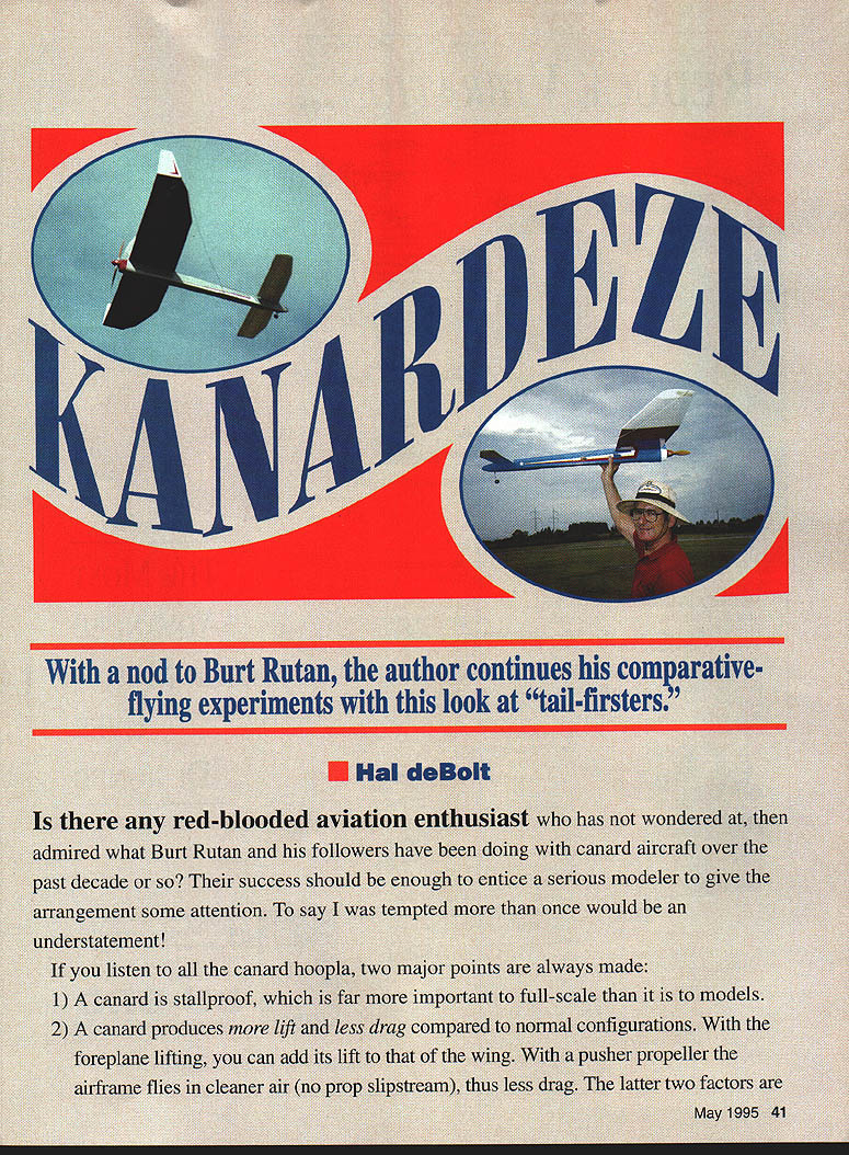
Kanardeze
Hal deBolt
With a nod to Burt Rutan, the author continues his comparative-flying experiments with this look at "tail-firsters."
Is there any red-blooded aviation enthusiast who has not wondered at, then admired, what Burt Rutan and his followers have been doing with canard aircraft over the past decade or so? Their success should be enough to entice a serious modeler to give the arrangement some attention. To say I was tempted more than once would be an understatement.
If you listen to all the canard hoopla, two major points are always made:
- A canard is stall-proof, which is far more important to full-scale than it is to models.
- A canard produces more lift and less drag compared to normal configurations. With the foreplane lifting, you can add its lift to that of the wing. With a pusher propeller the airframe flies in cleaner air (no prop slipstream), thus less drag.
The latter factors are tempting for any endurance model. That hope for something superior led us into this electric-powered Enduro.
My initiation into "tail-firsters" came with my first successful rubber-powered duration model—a single pusher whose flight is still a vivid memory. Fellow Flying Bison Doug Joyce demonstrated nearly 40 years ago how well a free-flight canard could perform. With some positive expectations, Kanardeze was launched.
The design stages were frustrating at first, yet the end result is a most delightful and exhilarating model to fly. It took two designs to accomplish it: I learned what the first did wrong and corrected it in the second.
A major obstacle was the lack of pertinent design data—no decent references. Burt Rutan kindly furnished details of his VariEze, which provided some basics. Andy Lennon's report on canard design in RCM offered clues, especially a formula to locate the mean center of lift. With basic aerodynamics to lean on, the design became mechanical in nature: a simple layout that allowed equipment weights to locate the center of gravity (CG) correctly and match the mean center of lift—until the first flights were made.
After the first launch we were very happy with the powered flight: the canard stepped right out into solid flight, handling very similar to a normal model. A few passes around the field, then a good climb angle brought it to altitude for glide tests. When the motor cut, it dropped into a steady glide that looked pretty fast and somewhat sinking. Up trim bled off speed and lowered the sink rate. However, at a low-speed point the nose suddenly dropped into a steep dive—very scary.
On the second scare, full up had no effect for several seconds, then suddenly "grabbed" and produced a stall. Everything was fine until the courage was gained to slow down again, which created a repeat. With reserve power it went back up to altitude and the same action occurred several times. There was no indication of a conventional wing stall; it appeared that the foreplane simply quit lifting and allowed the nose to drop. As long as speed was maintained everything was fine, so a landing was uneventful.
At the lunchtime bull session the problem was quickly labeled "Canard Syndrome." All sorts of causes and possible cures were discussed at length, with no logical answer. Having no positive data for canard balancing and foreplane angles of attack, we decided to experiment.
- Moving the CG forward 1/2 in increased glide speed and sink rate, but did not cure the syndrome.
- Moving the CG back as much as 3/4 in produced no help.
- Changing foreplane incidence produced no consistent effect.
Reviewing research on canards, we found minor mentions of similar flight characteristics; the only cure often suggested was simply "don't fly too slowly." The bull session after our outing centered on the idea that the foreplane appeared to lose all lift—"quit flying." A lifting surface needs forward speed to create lift; at low speeds lift disappears. Due to Reynolds-number effects, a wider-chord surface will have a lower zero-lift speed than a narrower-chord surface. If two surfaces fly at the same speed, the lesser chord will reach its zero-lift speed sooner than the wider-chord surface. In the canard case the foreplane could reach zero lift while the main wing still produced lift, so the lift proportion between wing and foreplane disintegrated. This made the cause of Canard Syndrome clear.
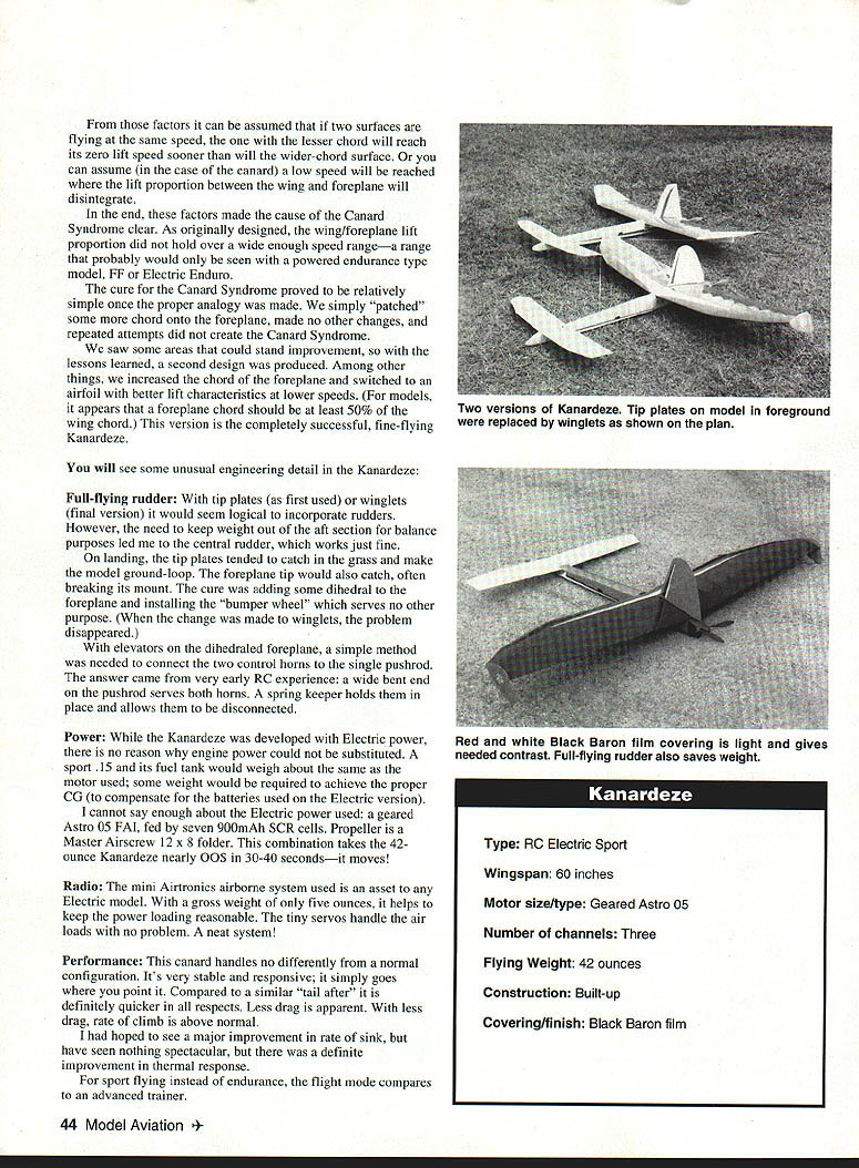
The cure proved relatively simple once the analogy was made: add chord to the foreplane. With the foreplane chord increased (and the airfoil changed to one with better low-speed lift), repeated attempts no longer recreated the syndrome. It appears the foreplane chord should be at least 50% of the wing chord.
You will see some unusual engineering detail in the Kanardeze:
Full-flying rudder
With original tip plates (and later winglets) it seemed logical to incorporate rudders. However, the need to keep weight out of the aft section for balance led to a central rudder, which works fine.
On landing, the tip plates tended to catch in the grass and make the model ground-loop. The foreplane tips would also catch and sometimes break mounts. The cure was to add some dihedral to the foreplane and install a small "bumper wheel" (which serves no other purpose). When winglets replaced tip plates, the problem disappeared.
With elevators on the dihedraled foreplane, a simple method was needed to connect the two control horns to a single pushrod. A wide bent end on the pushrod serves both horns; a spring keeper holds them in place and allows easy disconnect.
Power
While Kanardeze was developed with electric power, an engine could be substituted. A .15 and its fuel tank would weigh about the same as the motor used; some ballast would be required to achieve the proper CG to compensate for the batteries.
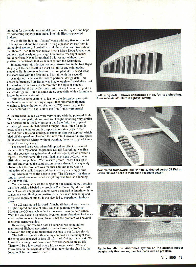
The electric installation used a geared Astro .05 FAI motor, fed by seven 900 mAh SCR cells, and a Master Airscrew 12 x 8 folding propeller. This combination takes the 42 oz Kanardeze nearly 900 ft in 30–40 seconds—it's quick.
Radio
A mini Airtronics airborne system is recommended. With a gross weight of only about 5 oz, it helps keep overall weight reasonable. Tiny servos handle the loads without issue.
Performance
- Handling: The canard handles very similarly to a normal configuration—stable, responsive, and quick.
- Drag and climb: Less drag is apparent and rate of climb is above normal.
- Sink rate: No spectacular improvement in rate of sink was seen, but there was a definite improvement in thermal response.
- Sport flying: For sport rather than endurance, the flight mode compares to an advanced trainer.
Specifications
- Type: RC electric sport
- Wingspan: 60 in
- Motor: Geared Astro .05 FAI
- Power: Seven 900 mAh SCR cells, Master Airscrew 12 x 8 folding prop
- Channels: Three
- Flying weight: 42 oz
- Construction: Built-up, stressed-skin wing
- Covering/finish: Black Baron film
Construction
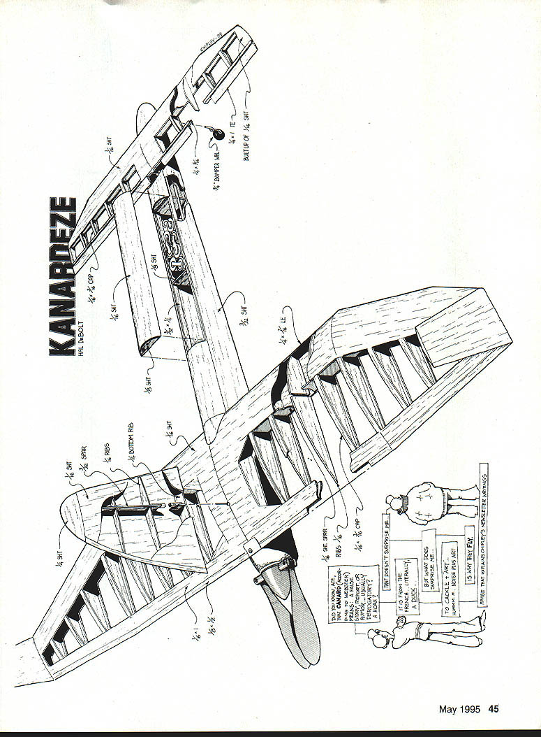
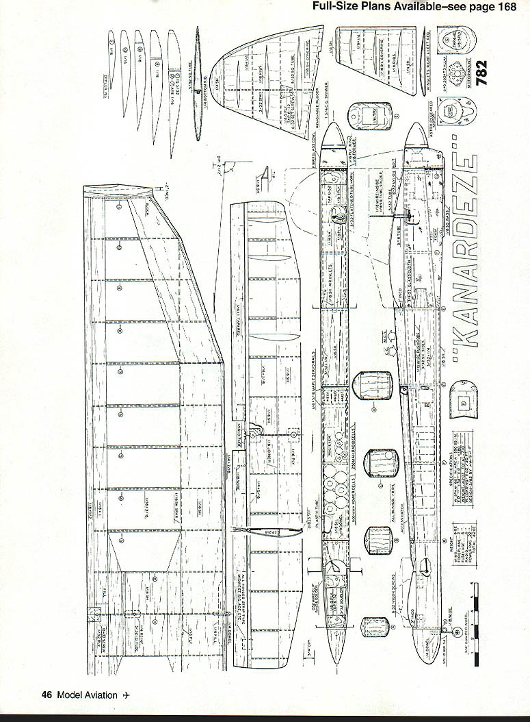
Wing
The Schuemann planform is advantageous for a canard because it moves the center of lift rearward. Winglets proved to improve performance over the original tip plates, though they are trickier to install. A brass tube bearing for the rudder linkage is required so it can be removable.
The stressed-skin structure has ample strength and does not depend entirely on internal structure, so there are a minimum number of parts and a very light, strong assembly.
Assembly sequence:
- Partially assemble the two panels, then join them. Use a straight piece of 1/16 x 3" center leading-edge (LE) sheeting. Join tapered tip portions with cyanoacrylate (CyA).
- Use a "jig strip" at the LE to curve the sheeting so it conforms to the lower airfoil. Use forward ribs as a guide to locate the 1/16" sheet spar on the LE sheeting. Spot-glue with CyA.
- Add all forward ribs except the center one. Using aft ribs as a guide, locate TE sheeting and install aft ribs except the center one. Leave recesses for spar material in the tip area until top sheeting is installed. Add the LE strip.
- Assemble the opposite panel to the same point using the first panel as a guide for chord width.
- Join the two panels at the center. Use a 2 x 4 chordwise to establish dihedral and assure the raised panel is true to the building board.
- Install dowel reinforcement at the LE, the 1/16" plywood spar joiner, and the 3/32" center rib. Add the 1/4" sheet that supports the rudder bearing and the TE fill that supports the attachment bolt.
- With one panel still on the board, install all top sheeting and cap strips using aliphatic glue for working time. Repeat for the opposite panel.
- Add TE strips, then carve and block-sand to finish the basic assembly.
Winglets
- Simple sheet-balsa structures; a right and a left are required (one side of the airfoil is flat).
- Fabricate outline from 1/16" sheet, install ribs, add other side sheeting.
- No LE required; joined sheeting is sufficient. Block-sand to contour.
- Install winglets on tips with balsa spacer blocks. Establish a 2° winglet incidence angle, then carve the winglet airfoil into the blocks, maintaining the 2° angle.
- Alter the winglet saddle so the winglet will be vertical when both wing panels have equal dihedral. Cement spacer blocks to tips and shape to the tip airfoil.
Install the 5/32" I.D. brass rudder bearing tube at wing center. Drill with a drill press for alignment, using a pilot drill first. The tube should be flush with the lower surface and protrude slightly from the top to act as a stop when the rudder is in place. Lock in with CyA.
Foreplane
Assembly is similar to the wing until ready for elevators. Install center mounting plates before top sheeting. Fit elevators to the foreplane strip as ailerons would be to a wing. Homemade brass-tube control horns are recommended for compact spacing. Seal elevators with film since they can affect directional control.
Rudder
Simple sheet-balsa structure with a symmetrical airfoil; use strip jigs to raise sheeting from the bench so it conforms to the airfoil as ribs are installed. Install spar first, followed by ribs using the jigs. Attach a 7/32" I.D. square brass connection tube aligned to the spar with thick CyA; make sure it is centered.
After top sheeting is complete, inset a 1/8" plywood screw plate flush with the sheeting. Drill and tap for a 6-32 screw to hold the rudder in place. Drill carefully so the drill just pierces one side of the tube inside the rudder. Add block tip and TE edge strip and block-sand to contour.
Fuselage
The fuselage is a typical box with some fairing. Start by fabricating sides and bulkheads. The sides should be precise—the lower edge is the line of flight and reference point. When the flats of wing and foreplane airfoils are parallel to this lower edge, they are at correct incidence angles, so no surface-mount angles are required.
Use the "centerline method" for fuselage assembly to assure alignment. Mark bulkhead spacing on the board centerline. Because the motor-mount bulkhead extends below the fuselage lower edge, commence spacing at the board edge and temporarily nail the motor-mount bulkhead to the board edge to assure true alignment. Erect bulkheads, locate top longerons, and cement them in place.
Block up the motor mount to required downthrust and right-thrust angles and glue. Add bottom and side sheeting, install wing saddle and center-section doublers, install the wing and check incidence, fit and glue the tailplane assembly, cut out and fit the cowl, finish-sand, and cover with film. Install hardware.
Equipment installation
- When installing the elevator servo, remember that with a canard, down elevator produces upward flight—not downward as usual. Verify transmitter orientation: down elevator = up stick.
- Shift radio and power batteries to locate the CG correctly.
Assembly alignment
- Slip the wing into its mount. Block the fuselage on a smooth tabletop so it is square. Measure from each wingtip to the table and adjust the wing saddle as required.
- Insert a straight pin atop the centerline of the forward equipment compartment bulkhead. Measure from this pin to each wing panel TE at the tip; adjust until equal. Use the wing mounting screw hole as a guide to drill and tap the required hole in the fuselage mount (use a tapered drill).
- Install the foreplane by aligning the rear mounting screw hole with the fuselage centerline. Drill and tap, attach with the screw, and use a pin at the top center of the motor-mount bulkhead to measure from pin to each foreplane TE tip; drill and tap the forward mounting plate when aligned.
- With both surfaces mounted securely, step back 10–20 ft and note spanwise alignment of foreplane to wing. Adjust the foreplane saddle if misaligned.
- Double-check incidence angles: using the lower edge of the fuselage sides as reference, measure to the center of each leading edge and to the trailing edges. The difference between LE and TE measurements should match the drawing.
Balance
Check CG now; major changes are easier before covering. With all equipment in place, put a piece of 1/4" square on a riser and balance the fuselage on it. Mark the location. The point shown on the plan is optimum, but the canard will fly safely over or under the usual CG range. If your model balances within 1/2" of the point shown, proceed to covering. When complete, make a second balance check.
Covering
Use any light covering except heavy fabric or heavy paint. Black Baron film is quick to apply, durable, and comes in many colors. For visibility at altitude, red and white contrast best.
Preflight
There is not much to preflight on an electric model beyond ensuring all systems are "go" and batteries charged. Check elevator throws and balance. Remember: down elevator = up stick. Verify right/left and motor operation.
A word of caution about folding props: ensure the folding mechanism has a stop to prevent blades from folding past hinge lines. With a pusher prop the fuselage does not act as a stop; one blade folded and the other not will cause severe vibration.
For the first flights it is best to have a helper hand-launch while you stand by with the transmitter. With power off, launch flat and brisk—no nose-up. Once launched, fly it to a landing to get a feel for procedures. If the glide looks correct, switch the motor on shortly after the next release. Kanardeze accelerates quickly.
Flying and trimming
Fine-tuning is done in two stages: power mode then glide mode.
- Trim checks: make a couple of laps and note drift and climb angle. Then bump up to a 45° climb with elevator and neutralize elevator to check whether the angle holds. Power-on trimming is done by adjusting foreplane incidence.
- Objective: have little or no climb angle when launched flat with elevator neutral. If there is a diving tendency, add positive incidence to the foreplane (shim up the leading edge). If there is too much climb, reduce foreplane incidence (shim under the trailing edge).
- Glide checks: at altitude, flatten the climb with elevator and cut the motor. With neutral elevator the glide should be flat and quick. Glide attitude fine-tuning is done with balance. If the nose is high or the model "stally," move the batteries forward. If the glide angle is too steep, move batteries rearward.
Landing: the glide is flat and there is some speed, so use a long approach and avoid extreme flare to prevent a stall. Despite a fast landing, Kanardeze slips easily through grass to a stop.
Kanardeze responds exceptionally well to thermals, often rising vertically on them—an impressive characteristic.
Final note: performance evaluation was done by comparative flying against a similar high-performance normal-configuration model. Results were very encouraging. Good luck, and have fun with your tail-firster!
Transcribed from original scans by AI. Minor OCR errors may remain.

