
Kansas Wakefield Champ
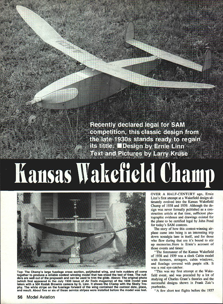
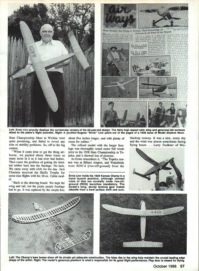
Over a half-century ago Ernie Linn's first attempt at a Wakefield design evolved into the Kansas Wakefield Champ (1938–1939). Although the design was never formally published as a construction article at the time, sufficient photographs and drawings existed to have the plane certified legal for today's SAM contests. The model proved to be a rugged, stable contest ship that handled Kansas flying conditions well — gusty and unpredictable — and remains a classic of the era.
Ernie Linn's account
The forerunner to the Kansas Wakefield was a sleek cabin model with formers, stringers, cabin windows and a fuselage covered in purple silk — a real eye‑catcher. Ernie's first Wakefield attempt followed much study of Charles Grant's theories and the successful designs shown in Frank Zaic's yearbooks. A few short test flights before the 1937 State Championship Meet in Wichita were promising, but the model failed to reveal trim or stability problems until contest day.
At Wichita, Ernie packed the motor far beyond previous tests and then could not get the knotted rubber back into the fuselage. No luck — he came away with zilch for that day; Jack Chastain received the Skelly Trophy for some nice flights.
Back to the drawing board: Ernie kept the wing and tail but replaced the purple cabin fuselage with a simple box about five inches longer, providing plenty of room for rubber. The refined model was thoroughly tested under windy conditions prior to the 1938 State Championship at Topeka and showed lots of promise.
At Topeka (Billard Airport), Wakefields were ROG'd (rise‑off‑ground) from the blacktop runway. Ernie made a couple of excellent thermal flights and placed first in the event. He found that a folding prop significantly extended the glide portion of flight; a ball‑bearing thrust washer helped get the rubber out smoothly.
For 1939 Ernie further refined the model: a 17‑inch‑diameter folding propeller replaced the original 16‑inch freewheeling type, diagonal fuselage braces were eliminated, and the fuselage received double tissue covering. He fully tested the new model before taking it to the El Dorado site for the 1939 State Championships, where flying conditions were much more difficult.
One memorable 1939 attempt: Ernie wound the rubber behind shelter, then he and helpers carried the model into the open and hand‑launched it. A helper held a wingtip for several minutes during launch setup; when the helpers released the wing tips the wing folded and repairs were made back at the pits. Roy Wriston of Tulsa is credited with the first‑place finish in Wakefield in 1939, but because of his out‑of‑state residency, Ernie Linn's name was engraved on the Skelly perpetual trophy. As Ernie recalls with a laugh, "Roy got the prizes, but . . . we won the 1938 and 1939 State Championships on a technicality."
The finished ship:
- Wingspan: about 44 inches
- Weight: about 12 ounces
- Notable features: large fuselage cross section, polyhedral wing, twin rudders, optional folding prop (1939) and ball‑bearing thrust washer
Ernie noted that the 1938 and 1939 Wakefields placed in the top three at almost every contest they entered.
Construction
Fairly typical period construction is used. Precutting or prekitting many parts is recommended — this avoids interrupting assembly to hunt for a missing piece.
Materials and basic tips
- Cut wing ribs from 1/16" sheet; false ribs from C‑grain balsa.
- Use an aluminum template for the rib pattern, especially for the last four outboard ribs of each tip panel. Move the template down as each rib is cut so the far outboard ribs end up with no undercamber, providing automatic tip washout.
- Stabilizer ribs: cut from 1/16" C‑grain using an aluminum template of the center rib. Mark top and bottom spar positions on each rib before installing.
- Sheeting: 1/16" thick for wing tip pieces; 3/32" thick for twin rudder pieces. Lay patterns to maximize grain strength.
- If you've done your work well you should end up with roughly 80 parts ready to assemble.
Wing
- Pin down the lower front spar of the inboard panels, then the trailing edge (TE), and finally the leading edge (LE).
- When both main panels are complete, prop them up to the indicated angle and set the dihedral. Note the difference in dihedral location between the 1938 and 1939 versions on the plans.
- Pin down the tip panels. Once each tip panel is complete, prop it up to the correct angle and set the polyhedral joint relative to the main panel.
- Install gussets at both the dihedral and polyhedral breaks. Cut these from medium‑hard stock with the grain parallel to the long side of the gusset triangle.
- Sand the wing carefully to remove glue blobs and any protrusions that would show through the covering.
Stabilizer and rudders
- Build much like the wing: pin down the short and angled bottom spars, set ribs in place, and add the trailing edge. Ribs should butt firmly against the TE without being forced.
- Glue the leading edge and reinforce the center rib joint with gussets fore and aft.
- If you plan to mount a dethermalizer (DT) hook on the center stabilizer rib, double the center rib and sheet the area between the LE and the short bottom spar (both top and bottom) to spread shock loads.
- Twin rudders: assemble pre‑cut pieces. A 3/32"‑sq. vertical member butts into the 3/32" stabilizer mounting sheet at top and bottom. Rudders are not airfoiled but should have rounded, smooth edges.
Fuselage
- Build one side atop the other, separated by Saran Wrap or waxed paper.
- The 1939 version omits the 1/16" x 1/8" diagonal fuselage braces used on the earlier ship.
- Use a small right triangle to ensure crosspieces remain square; the fuselage will be only as square as these crosspieces.
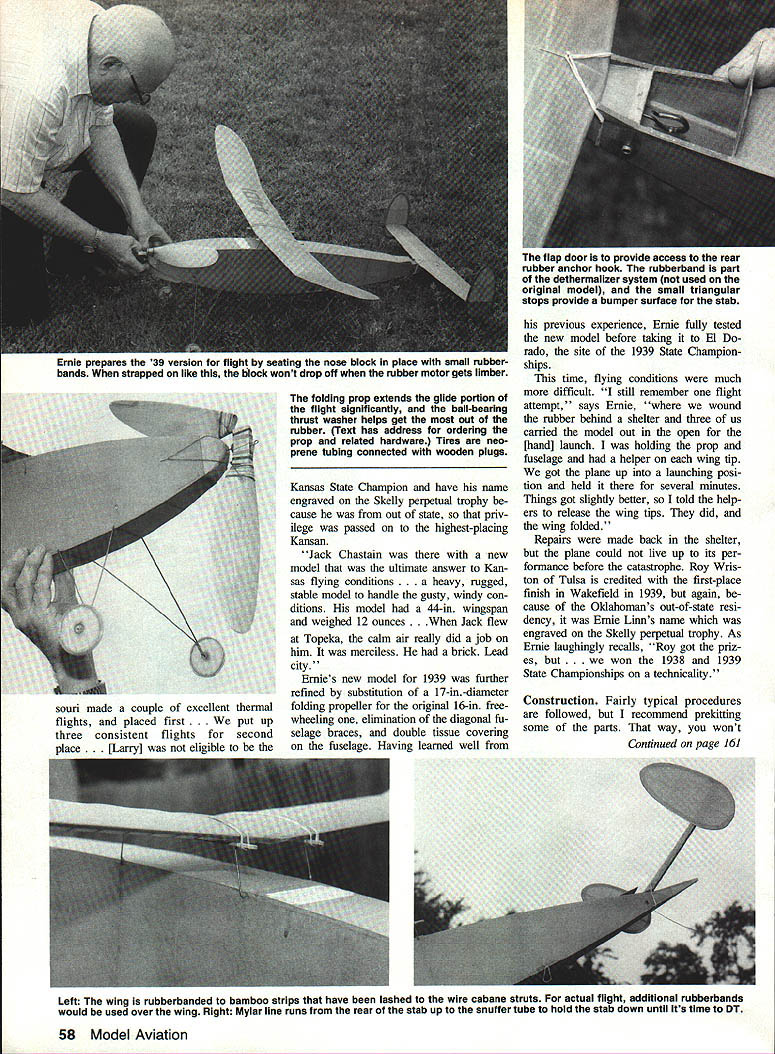
- The 1939 model includes a short horizontal piece between the first two upright stations for nose block retainer hooks — don't omit the retainer if you want the prop to remain secure after folding.
- Wing mount platform may be made from Popsicle sticks instead of bamboo. Lash wire struts to the horizontal crosspieces with thread, coat the wrapped thread ends with glue, and smooth glue across the top of the crosspieces so the tissue will not wrinkle.
- Landing gear fitted similarly to the wing mount: bend and solder wires as shown on the plan and lash with thread to the horizontal crosspieces.
- Wheels: laminate three layers of 3/32" balsa cross‑grained and sand to shape. Tires can be made from insulation of appropriate electrical wire or small neoprene fuel tubing connected with a small wooden plug.
- Complete the fuselage by adding the rear rubber hook and an access door to the hook area. Photos show an alternate DT system Ernie used; a similar system can be installed if desired.
Propeller
- A hand‑carved prop finishes the Champ nicely. The 1938 version used a freewheeling prop; the 1939 folding prop improves glide performance.
- If you prefer not to cut your own blank, suitable predrilled prop blanks and hardware can be obtained from Old Timer Model Supply (Ken Sykora), Box 7334, Van Nuys, CA 91409.
Covering and finishing
- Use a highly visible tissue color (orange or red recommended).
- Brush all framework with at least three coats of thinned 50/50 nitrate dope, sanding lightly between coats to reduce balsa fuzz.
- After covering wing, stab and rudders, shrink tissue with water from a pump spray bottle. Correct any warps (steam out) before flight testing.
- Suggested dope coats: tail — two coats; wing — four coats; fuselage — six coats to seal the tissue.
- Double‑covering the fuselage: apply the first layer with grain lengthwise, shrink with water, then apply one coat of vertical‑stroked nitrate. Add a second layer with grain vertical (cross‑grained to the first), shrink, allow to dry, then dope. Brush at least three more coats of 50/50 nitrate or until a definite sheen develops. Double covering greatly reduces punctures and DT damage.
Flight trimming
Rubber and motor
- The original plan calls for 5/8" brown T‑56 rubber. A modern equivalent is the type sold by Sig. If using 5/8" FAI or Champion rubber, limit the motor to 24–26 strands (12 or 13 loops). Excessive rubber in the unbraced 1939 fuselage may stress the structure.
Test glides
- Install enough rubber to balance the model and begin test glides.
- Start by tossing the model from shoulder height, aiming at a spot about 50 ft. away.
- If the CG is correct but the model still dives, shim up the trailing edge of the stab in 1/32" increments until the model flares or balances properly.
- If the glide is too steep, try balancing slightly tail‑heavy.
- Adjust rudders to give a gentle left turn in calm air and a right turn in a strong wind.
Powered trimming
- Begin powered flights with about 100 turns wound into the motor; release nose level. The model should climb slightly then float to the ground.
- Shim the nose block until a gentle climbing right turn is achieved on about 200 turns.
- As more turns are added, ensure the model continues to turn right. If the airplane hangs on the prop, add downthrust until the ship climbs on its wing, not on its prop.
- After a reliable power pattern is obtained, use small rudder tabs or stab tilt to trim the glide.
Landing and stab adjustment
- Adjust the stabilizer in 1/32" increments until the model floats smoothly down to a two‑point landing on its main gear.
- If it stalls or "gallops" to the ground, shim the leading edge of the stabilizer in 1/32" increments until a correct glide path is obtained.
Notes, anecdotes and final thoughts
- About five or six white service stripes were installed on Ernie's ship before it was lost at the State Championship Meet in Wichita.
- The folding prop and ball‑bearing thrust washer are recommended upgrades for improved performance in calm air.
- Ernie proudly noted that the 1938 and 1939 Wakefields served him well and placed highly at almost every contest entered. May your version of the Kansas Wakefield Champ bring you comparable success.
Ernie Linn welcomed correspondence from modelers building the design: 3505 E. Mt. Vernon, Wichita, KS 67218.
Transcribed from original scans by AI. Minor OCR errors may remain.

