
KC CLIPPER
REVISITED
Keith E. Dentel and William R. Murray
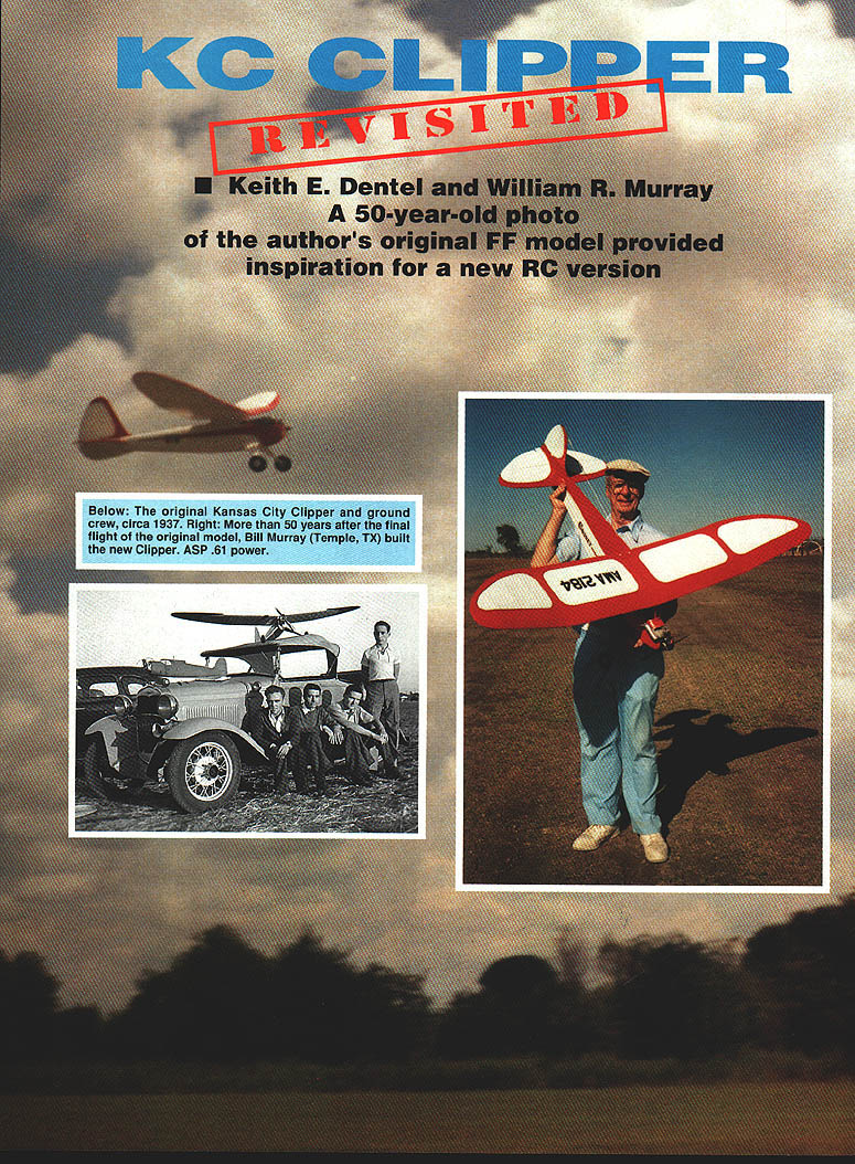
A 50-year-old photo of the author's original FF model provided inspiration for a new RC version.
The saga of the Kansas City Clipper began in the early days of modeling. Many of us in the Kansas City area were successfully designing and flying rubber-powered models in the late 1920s and early 1930s. It was very difficult to afford one of the new gas model engines in the Depression years, but I managed to get one of the first Ohlsson engines.
I designed and built my first gas model in 1936. It had an eight-foot wingspan and was powered with my new Ohlsson .60. I had some good flights from that first design, but disaster struck one windy day at Old Richard's Field, just outside Kansas City. Others patiently stayed grounded, but I flew! It headed straight into the wind and lifted like an express elevator; then, at about 150 feet, it suddenly nosed over, came roaring straight down, and plowed in. It was a total loss, and the crankshaft on my new Ohlsson .60 was bent! How I wished that I had waited for better wind conditions as the others had, or perhaps adjusted the trim a bit. Too late—it was gone.
Like the mythical Phoenix, the Kansas City Clipper concept emerged from the shattered remains of that first gas-powered model. Shortly after that fatal crash, the design was conceived and I made my final drawings in early 1937. The three-views really looked good—it wasn't boxy, like most of the early designs.
The planked oval-cross-section fuselage and elliptical outer wing panels made for some fairly difficult construction, but in spite of that I finished the Kansas City Clipper in 1937. It was covered with silk, clear doped with black trim, and finished with two coats of Packard car cream lacquer.
The model weighed in at just under six pounds, and the repaired Ohlsson .60 provided sufficient power for gentle climbs. Stability was excellent, and flights concluded with a good flat glide slope.
I built the wing in three sections, and the landing gear plugged in, which made it convenient for packing and shipping. My folks shipped the model to me in Burbank, California, where I had gone in 1938 to complete my aeronautical engineering studies.
The Clipper's last flight was in 1939, with an eyedropper more gas than I should have used. It climbed at its usual gentle angle and headed southeast. I knew right away that a chase was necessary, so my buddy and I cranked up the old Model A and followed as best we could, but we lost sight of it.
We continued in the general flight direction, where we spotted a crowd. Sure enough, it was the Clipper—it had glided into the side of a garage with no damage to anything or anyone, except that the engine and firewall bulkhead were pushed back into the fuselage. Not too bad, all things considered.
The Kansas City Clipper was later disassembled, boxed, and shipped back to my folks' attic in Kansas City; later it went to my attic in Falls Church, Virginia. I restored it in 1988 and offered it to the AMA Museum, where it now resides in all of its original splendor.
Bill Murray of Temple, Texas will continue the saga of the Kansas City Clipper, and tell you how he rediscovered it in late 1989:
I became acquainted with Keith in late 1989. We continued our acquaintance by letter and phone, and we exchanged photos of models that we had built.
One was the Kansas City Clipper—it struck my fancy, and I wanted one very badly! It was an eye-catcher and was ahead of its time. I didn't know at the time that I was about to start one of the most interesting and rewarding projects that I have ever undertaken.
After seeing that picture of the Kansas City Clipper, I phoned Keith and told him that I just had to build one, and I was leaning toward a radio-controlled version. When he told me that he had a quarter-scale three-view drawing, I was elated. That was all I needed to get started, and start I did.
I decided that the original lines had to remain essentially unchanged, but some construction changes would be required—most notably, movable control surfaces. Another obvious requirement would be access to install and service the radio gear, as well as a fuel tank. I also wanted to beef up the fuselage to withstand occasional bumpy landings.
None of these contemplated modifications would change the model's appearance or airworthiness, so I got started on detailed full-size plans. At last I was ready to get this jewel underway!
This is not a beginner's project, but I'll wager that most modelers can get the Kansas City Clipper in the air. Many will welcome a change of pace and the challenge of doing something different.
GENERAL CONSTRUCTION NOTES
I used tracing paper to copy parts from the plans, and attached the tracings to the wood with 3M spray adhesive. The paper peels off after cutting, at which time the parts should be numbered or otherwise identified. You could kit the entire model before construction begins.
Adhesives used: cyanoacrylates (CyA); epoxies with six- to 45-minute working times; sandable aliphatic-resin glue; and Sig-Ment model airplane cement.
The usual assortment of tools were employed. Some favorites are:
- A Zona saw with a detachable 4-1/2-inch blade without a stiffener across the top. You can ripsaw with it, and it was just the thing to saw the access hatch from the fuselage.
- Straight pins of all sizes; I got them from a yard-goods store. The little fine ones are thin and sharp, and rarely split small pieces of balsa.
- Rocket City pin clamps.
- A good stock of single-edge razor blades and #11 X-Acto blades — always use a sharp blade.
- Strips for laminating were soaked in ammonia water. I then used aliphatic-resin glue and bent these strips around an outline of pins previously placed over the plans. These strips were then pinned in place and allowed to dry.
Fuselage Jig
Make jig blocks from 2 x 4 scraps. Cut six pieces six inches long; the ends must be square, as they will be set on end to block up the fuselage many times during construction. (Since a 2 x 4 actually measures 1-1/2 x 3-1/2, two of the fuselage jig blocks can double as dihedral supports.) Cut a slot in the middle of two blocks, and cement a 1/8 x 1/4 x 6 balsa strip on one to raise the height to the proper amount to block the inside wing panels up for dihedral.
Cut five pieces 1 x 6 from scrap 3/8 plywood. These building aids are used in conjunction with the jig blocks to prop up the fuselage.
The fuselage must be blocked up on the crutch many times during construction to dry-fit various components. The top of the crutch (side longerons) is the thrust line, and it should be level to check wing and stabilizer incidence.
To achieve this, put two of those 1 x 6 building-aid sticks on top of the crutch, between bulkheads, so that they project beyond the fuselage enough to put a nine-inch carpenter's level on them. After leveling the crutch, check the incidence with a Robart meter.
FUSELAGE CONSTRUCTION — PRELIMINARY
Bulkhead notches need to be sized accurately; the longerons should fit snugly, to facilitate fuselage assembly. To meet this requirement, make several notch sanders from 1/4-square hard balsa and 1/4 x 1/2 hard balsa scraps about four to five inches long. Sand them down a bit to compensate for sandpaper thickness; glue sandpaper to three sides. These do a great job on bulkheads (and on ribs). The desired snug fit is very rewarding.
The bulkheads, sub-fin and rib doublers were cut from Lite Ply. Birch plywood was used for the firewall, pylon and other plywood parts. I also used 1/32 and 1/64 plywood in some places. The fuselage top and bottom longerons were cut to shape from 1/4 hard balsa sheet in one continuous length. They are both 1/2-inch deep, to fit in the bulkhead notches.
Control linkages: I used Gold-N-Rods with blue sheaths for rudder and elevator; cable and tubing for the throttle.
Before laminating the firewall, cut the slot for the landing gear (LG) platform in the 1/8-inch plywood. When the epoxy cures, drill and install blind nuts for the motor mount; drill holes for fuel lines and throttle tubing. Shim the motor mounts for about two degrees right and down thrust.
Finish LG supports, including brass tubing. Epoxy the rear support and triangle-stock bracing to BH 3. Epoxy the front support to the LG platform. Epoxy balsa stiffeners to the top of BHs 3, 4, and 5.
Using BH 3 as a pattern, outline a reinforcement area on 1/16 plywood. Cut and epoxy these doublers to both sides of BHs 4 and 5.
Using BHs 3 and 6 for patterns, outline hatch formers 3A and 6A on 1/8 Lite Ply; cut and sand to exact match, and lay aside.
Pin the top and bottom longerons over the plan; mark and number each BH location on the sides and tops. Remove.
Make the fuselage crutch from side longerons and temporary crosspieces by pinning 1/4-square hard balsa strips over the top view of the fuselage. Make vertical razor saw cuts in longerons where they bend inward at BH 8 to weaken them a bit. They will bend easier and not bulge beyond that point. Force epoxy in the cut to restrengthen it.
Fit the longerons at the rear and CyA them. Cement 1/4-square balsa crosspieces just behind the firewall, at BH 4 and in front of BH 8. Remove after the fuselage is built. Mark and number each BH location on the side and top of both longerons. Remove—the crutch should hold its shape.
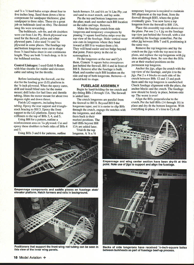
FUSELAGE ASSEMBLY
Begin by hand-holding the crutch and dry-fitting BHs 2 through 13A. The firewall is added later.
The crutch longerons are parallel from the firewall to BH 8. Beyond BH 8 the longerons taper, and it is easier to slip BHs through the crutch, engage the notches with the longerons, and slide them back to their marked positions. The half-BHs beyond BH 13A are added later.
Trial-fit the top longeron. A 1/4 x 1/2 temporary longeron is required to maintain BH alignment at the top front, from the firewall through BH 5, where the pylon eventually goes. You now have a top longeron from the firewall to BH 13A.
Place this assembly top-side-down over the plans. Put one 2 x 4 jig on the fuselage just behind the firewall, with a slot straddling the fuselage centerline. Put the other jig between BHs 7 and 8, positioning it the same way.
Remove the top longerons and lay the crutch on the jigs, align the top next to the plans, and replace the top longerons with jig slots straddling them. Be sure that the BHs are at their marked positions on the permanent top longeron.
Anchor the jigs, align the crutch with the top view of the fuselage, and pin it to the jig. Put 2 x 4 blocks on each side of the crutch between BHs 12 and 13 and push them until the top longeron is sandwiched. Check fuselage alignment with the plans, then anchor blocks and the crutch. The fuselage should be firmly in place, bottom-side up.
Align the BHs perpendicular to the crutch. Put the half-BHs (14 through 16) in place and dry-fit the bottom longeron. With everything in place, CyA all joints except the temporary top longeron. Keep the fuselage anchored in place.
As you position the firewall, slip the LG platform into the slots in the back of the firewall and in BH 2. I used 45-minute epoxy; that gave enough time to accurately align the firewall with no offset. When the epoxy has cured, add the triangular bracing and gussets at the firewall and BH 2. Servo rails can be added at this time. Remove the fuselage and admire!
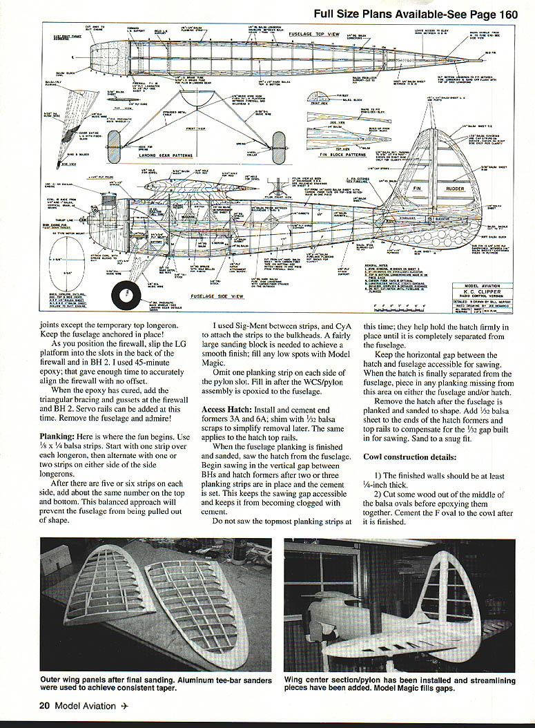
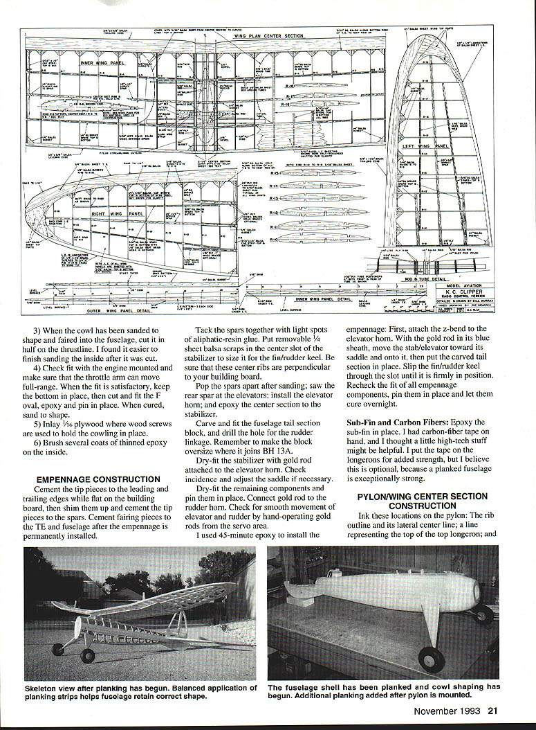
Planking
Here is where the fun begins. Use 1/8 x 1/4 balsa strips. Start with one strip over each longeron, then alternate with one or two strips on either side of the side longerons.
After there are five or six strips on each side, add about the same number on the top and bottom. This balanced approach will prevent the fuselage from being pulled out of shape.
After the strips are in place, sand the areas smooth. I used Sig-Ment between strips, and CyA to attach the strips to the bulkheads. A fairly large sanding block is needed to achieve a smooth finish; fill any low spots with Model Magic.
Omit one planking strip on each side of the pylon slot. Fill in after the WCS/pylon assembly is epoxied to the fuselage.
Access Hatch
Install and cement end formers 3A and 6A; shim with 1/32 balsa scraps to simplify removal later. The same applies to the hatch top rails.
When the fuselage center is finished and sanded, saw the hatch from the fuselage. Begin sawing in the vertical gap between BHs and hatch formers after two or three planking strips are in place and the cement is set. This keeps the sawing gap accessible and keeps it from becoming clogged with cement.
Do not saw the topmost planking strips at this time; they help hold the hatch firmly in place until it is completely separated from the fuselage.
Keep the horizontal gap between the hatch and fuselage accessible for sawing. When the hatch is finally separated from the fuselage, piece in any planking missing from this area on either the fuselage and/or hatch. Remove the hatch after the fuselage is planked and sanded to shape. Add 1/32 balsa sheet to the ends of the hatch formers and top rails to compensate for the 1/32 gap built in for sawing. Sand to a snug fit.
Cowl construction details
- The finished cowl walls should be at least 1/4-inch thick.
- Cut some wood out of the middle of the balsa ovals before epoxying them together. Cement the F oval to the cowl after it is finished.
- When the cowl has been sanded to shape and faired into the fuselage, cut it in half on the thrustline. It is easier to finish sanding the inside after it is cut.
- Check fit with the engine mounted and make sure that the throttle arm can move full-range. When the fit is satisfactory, keep the bottom in place, then cut and fit the F oval, epoxy and pin in place. When cured, sand to shape.
- Inlay 1/16 plywood where wood screws are used to hold the cowling in place.
- Brush several coats of thinned epoxy on the inside.
EMPENNAGE CONSTRUCTION
Cement the tip pieces to the leading and trailing edges while flat on the building board, then shim them up and cement the rib pieces to the spars. Cement fairing pieces to the TE and fuselage after the empennage is permanently installed.
Tack the spars together with light spots of aliphatic-resin glue. Put removable 1/4-sheet balsa scraps in the center slot of the stabilizer to size it for the fin/rudder keel. Be sure that these center ribs are perpendicular to your building board.
Pop the spars apart after sanding; saw the rear spar at the elevators; install the elevator horn; and epoxy the center section to the stabilizer.
Carve and fit the fuselage tail section block, and drill the hole for the rudder linkage. Remember to make the block oversize where it joins BH 13A.
Dry-fit the stabilizer with Gold-N-Rod attached to the elevator horn. Check incidence and adjust the saddle if necessary.
Dry-fit the remaining components and pin them in place. Connect Gold-N-Rod to the rudder horn. Check for smooth movement of elevator and rudder by hand-operating Gold-N-Rods from the servo area.
I used 45-minute epoxy to install the empennage. First, attach the z-bend to the elevator horn. With the Gold-N-Rod in its blue sheath, move the stab/elevator toward its saddle and onto it, then put the carved tail section in place. Slip the fin/rudder keel through the slot until it is firmly in position. Recheck the fit of all empennage components, pin them in place and let them cure overnight.
Sub-fin and carbon fibers: Epoxy the sub-fin in place. I had carbon-fiber tape on hand, and I thought a little high-tech stuff might be helpful. I put the tape on the longerons for added strength, but this is optional, because a planked fuselage is exceptionally strong.
PYLON / WING CENTER SECTION CONSTRUCTION
Ink these locations on the pylon: the rib outline and its lateral center line; a line representing the top of the top longeron; and a line representing the top of the bottom longeron. Align the pylon on the fuselage and clamp it in place so that the top of the pylon is flush with the top of the top longeron. Check the incidence of the wings and adjust the pylon if necessary. When satisfied, glue the pylon to the fuselage using a fillet of epoxy and add triangular planking fairings at the sides.
Mark vertical lines representing the extended notches of BHs 3, 4, and 5. The marks are convenient for checking the built-in wing incidence and the fit of the pylon streamlining pieces, which must be slotted to fit over the extended notches of the BHs.
When dry-fitting the pylon to the fuselage, make certain that it fits snugly in the BH notches and in the cuts where it rests on top of the longeron. Also ensure that it is perpendicular to the crutch and that the bottom is parallel with the crutch.
Wing center section (WCS) ribs and adjoining ribs of the inner panels are the same size. Stack, sand, align and size the notches, drill the rod and dowel holes, etc.
Use 1/4-sheet balsa removable scraps to size the pylon slot and keep the center ribs perpendicular to the building board. No built-in tilts, please!
The WCS bottom spars end at the pylon slot.
The pylon should not project above the rib line, but it can be slightly below it.
I used a K&S wing rod package—3/8 rod, 1/2 tube, each 12 inches long. I cut the tube in half, one segment for each inner wing panel. Music wire and brass tubing were used in back.
WING PANEL CONSTRUCTION
Evenly tapered wing ribs require persistent sanding to remove high areas; scrapes of balsa will fill low spots. I used a 32-inch aluminum sander, similar to a toe bar, and attained excellent taper lines. This applies to the fuselage bulkheads as well.
I wanted an easy way to establish consistent depth at the trailing edges for rib capstripping. There are 3/32 capstrips on the wing ribs. So I CyAed a 3/32-square balsa strip to the bottom of the TE to serve as a jig for rib placement. Use 1/16-square balsa strips when 1/16 capstrips are specified. I did not remove these jig strips.
Because many ribs are different lengths, inaccuracies could creep in; therefore, I cut the ribs slightly long in the back and then sanded them to fit. At this point, I eyeballed the vertical size of each rib where it met the TE and sanded in any adjustments.
The inner wing panel (IWP) tapers slightly and narrows about a half inch. This makes the length and airfoil of each rib a little smaller going from the center section to rib 9. The airfoil difference is about the width of a pencil line, as the rib pattern on the plan illustrates. With this in mind, use the following procedure to cut and size these ribs:
- Cut out and notch ribs 1 through 8 using IWP rib 0 as a pattern (the same size as the center section ribs). Ink a centerline on each rib.
- Trim each rib to length and number them.
- Make rib 9 from the plan pattern and ink in the centerline.
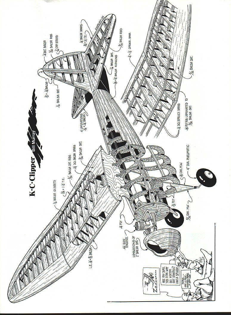
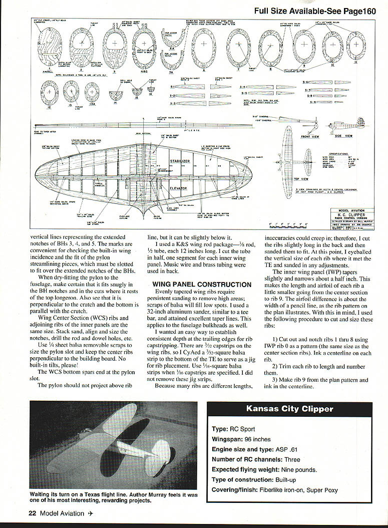
KANSAS CITY CLIPPER — SPECIFICATIONS
- Type: RC Sport
- Wingspan: 96 inches
- Engine size and type: ASP .61
- Number of RC channels: Three
- Expected flying weight: Nine pounds
- Type of construction: Built-up
- Covering/finish: Fiberlike iron-on, Super Poxy
Transcribed from original scans by AI. Minor OCR errors may remain.

