
Keith Rider R-4
The air-racing planes of the 1930s have always captured modelers' attention. In addition to their classic good looks, these airplanes have graceful lines and proportions that make them great subjects for rubber power. — Tom Nallen
Introduction / Background
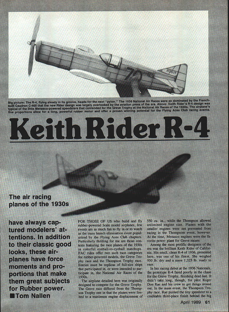
For those of us who build and fly rubber-powered scale model airplanes, few events are as much fun to fly in or to watch as the mass-launch elimination event popularized by Flying Aces Club (FAC) chapters. Particularly thrilling are contests featuring the race planes of the 1930s in colorful eyeball-to-eyeball matchups. FAC rules offer two such race categories for rubber-powered models: the Greve Trophy race and the Thompson Trophy race. Entries must be replicas of full-size ships that participated in, or were intended to participate in, the National Air Races of the 1930s.
The Greve race differed from the Thompson race in that the Greve planes were limited to a maximum engine displacement of 550 cu. in., while the Thompson allowed unlimited engine size. At the time, Menasco engines were the favorite power plant for Greve racers.
Among the most prolific designers of the era was Keith Rider of California. His small, clean R-4 of 1936 was one of his finest. The full-size R-4 weighed about 950 lb. dry and approximately 1,325 lb. ready to race.
In its racing debut at the 1936 Nationals, the prototype R-4 finished poorly in the chase for the Greve Trophy, dead last. After adjustments by pilot Roger Don Rae and his crew, the R-4 placed third in the Thompson Trophy race (behind the larger R-3 powered by a Pratt & Whitney Wasp) and won the Shell Cup at the Nationals.
Model Selection and Performance
I selected the slick little R-4 as a building project because of its fine proportions and suitability as a Greve Trophy mass-launch entry in FAC get-togethers. The model has more than lived up to expectations: it's perfect for those seeking a low-wing plane with lots of zip and strong contest potential.
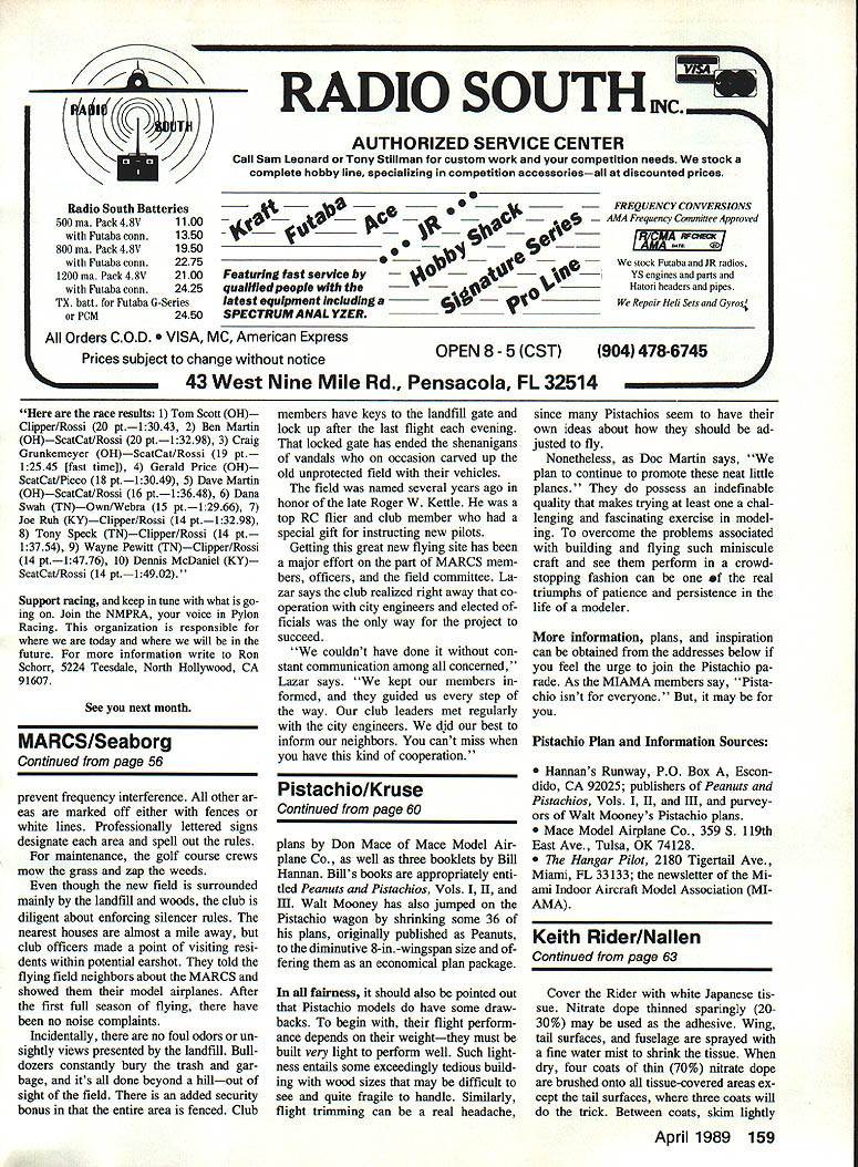
Several FAC pilots have proven the model's mettle in competition. At an FAC Nats in Dayton, OH, Glenn Rakow of Silver Spring, MD finished second in the Greve—unfortunately unable to retrieve his far-flying R-4 within the time allowed to make the final lap. At the FAC Nats in Geneseo, NY, Don Srull won the Greve with a sensational out-of-sight flight on the last lap.
Glenn Rakow and Don Srull have demonstrated that the model's performance is enhanced by increasing dihedral and adding slightly more stabilizer area than originally drawn. With a tip of the T-square to them, the published plan incorporates these changes. Srull's second R-4, the FAC Nats winner, was a blown-up 23-inch wingspan version.
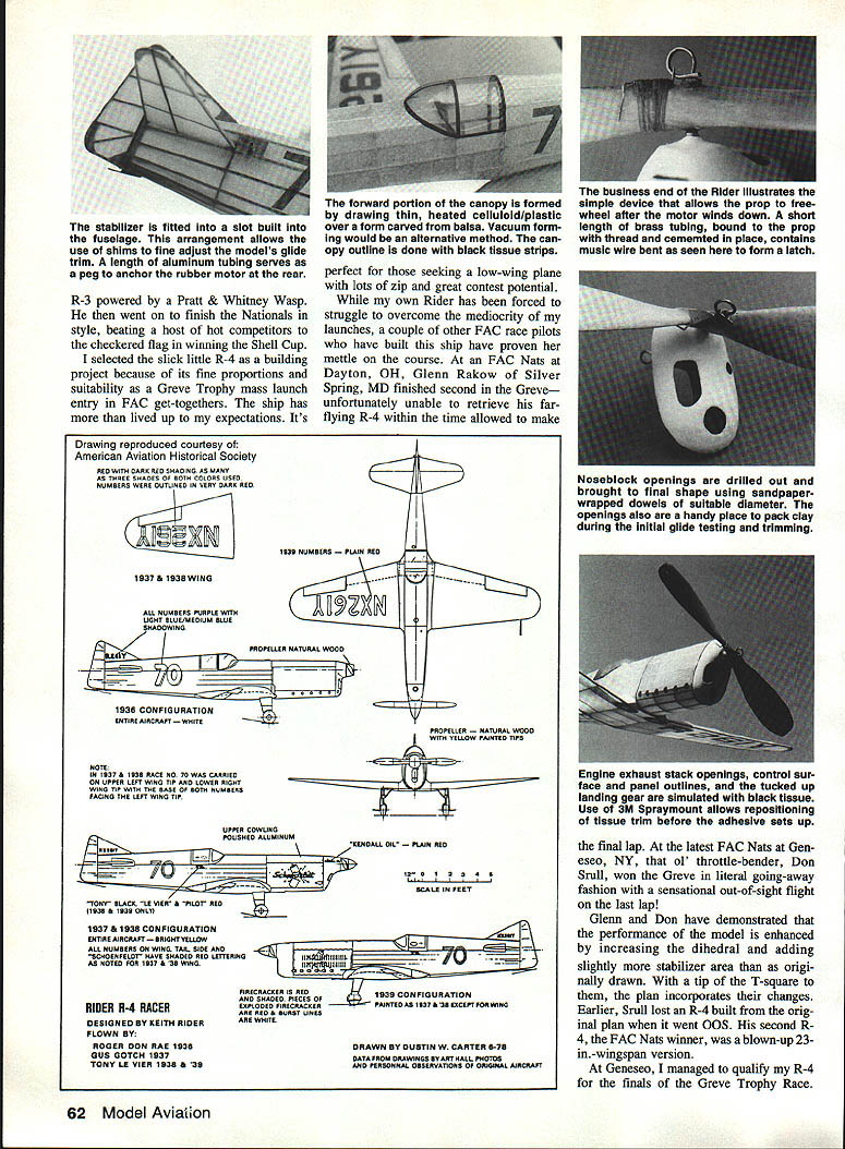
Because the prototype was active on the race scene from 1936 to 1939, undergoing many modifications and repaintings, there was some uncertainty regarding the correct color scheme for any one year. Drawings by Dustin Carter in the American Aviation Historical Society Journal (Fall 1978) resolved many of these questions. Only minor changes are necessary to convert the 1936 R-4 model to later "Firecracker" variants. The 1939 version flown by Tony LeVier is particularly notable among racing aircraft.
Construction
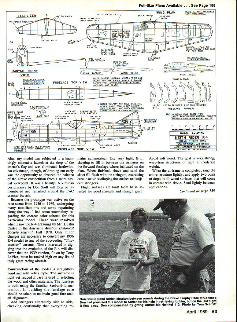
Construction of the model is straightforward. The airframe is light yet rugged if care is used in selecting the wood and other materials.
- Fuselage: Built using the familiar keel-and-former method. Maintain good fore-and-aft alignment while building. Add stringers alternately side to side, checking continually that everything remains symmetrical.
- Sheeting: Use very light 1/16-inch sheeting to fill in between the stringers on the forward fuselage where indicated on the plan. When finished, shave and sand the sheet fill flush with the stringers, exercising care to avoid scalloping the surface and adjacent stringers.
- Flight surfaces: Build from balsa selected for good strength and straight grain. Avoid soft wood. Aim for very strong, warp-free structures of light to moderate weight.
When the airframe is completed, sand the entire structure lightly and apply two coats of dope to all wood surfaces that will come in contact with tissue. Sand lightly between applications.
Covering and Finishing
- Cover the model with white Japanese tissue. Nitrate dope thinned sparingly (20–30%) may be used as the adhesive.
- Spray the wing, tail surfaces, and fuselage with a fine water mist to shrink the tissue. When dry, brush four coats of thinned nitrate dope onto all tissue-covered areas except the tail surfaces, where three coats are sufficient. Between coats, skim lightly with fine glasspaper to remove fuzz.
- After the final coat, rub over the fuselage and the flight-surface leading and trailing edges with a piece of worn-out, fine sandpaper.
Registration and race numbers, as well as control-surface and panel outlines (including canopy trim), are cut from tissue. Use 3M SprayMount to apply tissue trim; the spray adhesive permits easy repositioning if required. Consider covering the cockpit opening under the canopy with black tissue or light construction paper to prevent rubber-tube sputter (looks like a sick pilot, n'est-ce pas?) on the thin celluloid overhead.
Use sandpaper and a sharp knife to trim-fit the finished wing into the saddle and to the fuselage. Be certain the wing is fixed in place at the incidence angle shown on the plan and is perfectly trued up.
The stabilizer slides into a section temporarily left uncovered and open at the rear of the fuselage. This arrangement allows shimming of the stabilizer to achieve the desired glide trim.
Trim, Balance, and Glide Testing
- Ready the assembled airplane (less prop and rubber) for glide tests.
- Add clay to the nose block to bring the balance point to that indicated on the plan. Hand-launch the model a few times and shim the stabilizer and add or remove small increments of clay as needed to optimize the glide. Note this balance point.
- Install the prop and rubber. Wind the rubber motor until lightly tensioned, then pin the prop to prevent rotation. Using bits of lead or clay tucked securely inside the nose, rebalance the model at the balance point noted during the glide test.
Make trim adjustments one at a time (per flight) to avoid confusion and delays. Work up slowly on rubber motor turns, fine-tuning as you go. When final trim is reached, cover and finish the portion of the stabilizer slot that was left open.
Flying
The R-4 tends to turn leftward. Circle diameter can be adjusted with tweaks of left rudder and/or small amounts of side thrust or downthrust as required. Make small adjustments incrementally.
After working the model into trim, my first fully wound flight was 64 seconds in nice, light evening air. The model is very steady in flight, flying as if in a groove. It is a good airplane—lots of fun to build and fly.
Rubber and Prop
You have latitude in selecting a rubber/prop combination. A good starting point:
- Two loops of 5/8-inch rubber, 24 to 28 inches long
- Freewheeling 8-inch prop
Props may be carved from hard balsa, or you may use balsa or plastic props.
Canopy and Details
The forward portion of the canopy is formed by drawing thin heated celluloid or plastic over a form carved of balsa. Vacuum forming is an alternative method. Canopy outline is done with black tissue strips. Engine exhaust stack openings, control-surface panel outlines, and tucked-up landing gear are simulated with black tissue. Use 3M SprayMount for positioning the tissue trim.
Notes on Competition and Modifications
- Increasing dihedral and adding slightly more stabilizer area than originally drawn improves performance in contest conditions. The published T-square plan incorporates these changes.
- Several pilots have used blown-up versions (e.g., 23-inch wingspan) for better visibility/retrievability and contest success.
- "OOS" indicates out of sight.
Plans and Credits
Full-size plans available—see Page 188.
R-4 racer designed by Keith Rider. Flown by Roger Don Rae (1936); Gus Gotch (1937); Tony LeVier (1938 & 1939). Drawn by Austin W. Carter 6-70. Data from drawings by Art Hall, photos, and personal observations of the original aircraft.
Transcribed from original scans by AI. Minor OCR errors may remain.

