
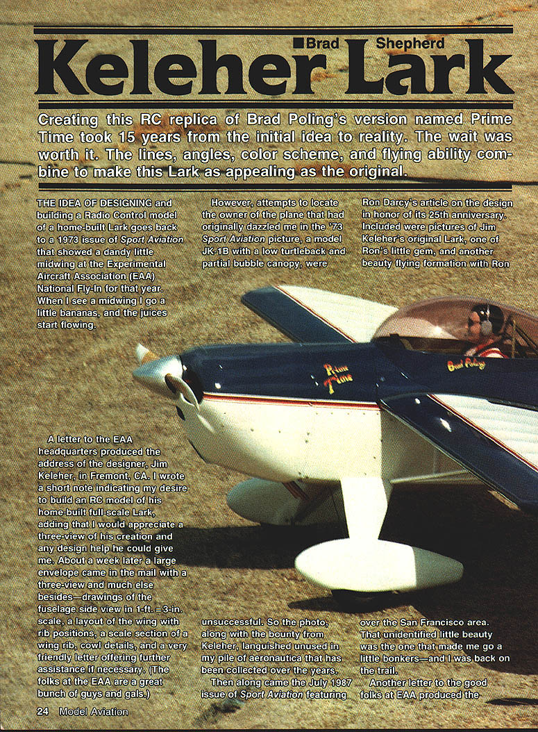
Keleher Lark
Brad Shepherd
Background
The idea of designing and building an RC replica of a home-built Lark began after seeing a 1973 issue of Sport Aviation that showed a neat little midwing at the EAA National Fly-In. Attempts to identify the owner of that particular airplane (a model JK-1B with a low turtledeck and partial bubble canopy) initially failed, but a letter to EAA headquarters produced the address of the designer, Jim Keleher, in Fremont, CA.
I wrote Keleher asking for a three-view and any design help. About a week later a large envelope arrived with a three-view and detailed drawings: fuselage side view (1 ft. = 3 in. scale), wing layout with rib positions, a scale wing-rib section, cowl details, and a friendly offer of further assistance. The material sat in my files for years until Ron Darcy’s July 1987 Sport Aviation article (25th anniversary of the design) revived my interest. That article included pictures of Jim Keleher’s original Lark and another striking example flown by Brad Poling of Concord, CA.
A subsequent letter to EAA produced Brad Poling’s address. Brad, a former airplane modeler who competed in the Plymouth meets, has been very cooperative and provided much inspiration and detail for this project.
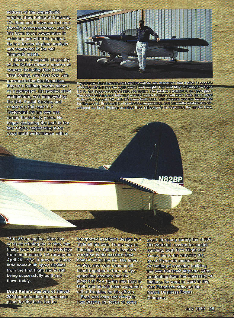
From Ron Darcy, Brad Poling, and Jack Cox I pieced together a capsule biography of Jim Keleher: he grew up in the San Francisco Bay area building model planes, studied naval architecture, worked for the U.S. Postal Service, and restored a full-scale L-2 Taylorcraft. He began designing the Lark in the late 1950s, engineering it for good performance on 75–85 hp engines. After five years of refinements, the prototype first flew from Fremont on April 26, 1962. The design proved successful and is still being built and flown.
Brad Poling and his Full-Scale Lark
Brad Poling was one of nearly 200 home-builders to purchase plans for the Lark, but he interpreted Keleher’s design in his own distinctive style. The lines, angles, and color scheme of Poling’s machine make it especially appealing; it has earned numerous trophies at EAA fly-ins.
Brad was born and raised in Fort Wayne, IN, and his early interest in model building led him to the Plymouth meets and to dream of building a full-scale airplane. After graduating from the University of Indiana he worked in San Francisco. In 1975 he began researching homebuilt designs and repeatedly returned to the Keleher Lark. He purchased plans and went to work, contacting Ron Darcy for construction guidance.
Not knowing how to weld, Brad enrolled in a night course and practiced on scraps of 4130 tubing until he was ready to weld the fuselage. Keleher’s plans call for large tubing sizes and a beefy spar—no gimmicks—resulting in a very stout airplane. A&P mechanic Jim Walter helped with many construction details during Brad’s three-year build, and good friend Larry Pinnock made the instruments work, helped with details, and did the finish painting.
A notable departure from standard practice on Brad’s Lark was elimination of rib stitching: ribs were glued, 1¼-in. cap strips were applied, and fabric was glued to the caps. After preliminary work (cowling and metal parts) Pinnock sprayed the aircraft with DuPont Centari acrylic enamel to a glossy finish.
Because Pinnock had more flying experience he made the first flight. Neither he nor Brad had flown a taildragger before, so they checked out in a Super Cub. After the first flight, Brad described the Lark as an easy, stable, docile airplane with excellent visibility and ground handling:
"Before I was off the end of the runway I knew it was an easy airplane to fly. It's very stable, just outrageously easy to handle. On landing you have such great visibility that it's hard to get really out of shape; once you're on the ground it rolls out beautifully. Since you sit on the centerline of the fuselage you can instantly detect drift in a crosswind and correct before you get into trouble. It's very, very docile."
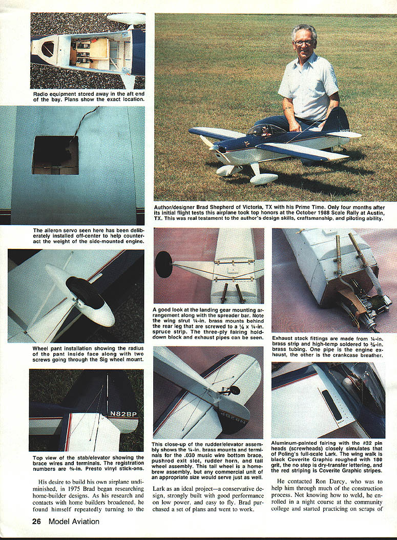
Only four months after initial flight tests the full-scale airplane took top honors at the October 1988 Scale Rally in Austin, TX.
From Inspiration to RC Model
Designing and building the quarter-scale RC replica of Brad Poling’s Lark (named Prime Time) took 15 years from initial idea to reality. In June 1988, 15 years after Keleher’s design first captivated me, the prototype model was ready for its maiden flight.
On June 23, 1988 at Steen Airstrip in south Texas I prepared the model with the wing and struts bolted on. After installing the show prop for pictures, I fitted the operating prop, started a .65 Saito, checked rpm, and taxied to the far end of the grass strip. At 4:30 p.m. I throttled up and in about 100 ft the Lark was flying—before any up elevator was applied. Response was excellent: loops, snaps, rolls, knife-edge flight, outside loops, outside snap rolls, spins with immediate recovery, and slow flybys all proved the model capable and predictable.
The first landing was rough—overcontrolling the elevator caused the model to flip on the last bounce, but damage was minor (a scuffed canopy). On subsequent flights I learned to use a longer approach, keep the model low at reduced power until crossing the edge of the strip, then cut throttle and let it settle onto the main gear, allowing the tail to lower as it slows. Don’t try a three-point landing on the first attempts; land on the mains.
Leon Folse photographed one flight and convinced me to do an inverted flyby on the second flight—despite my apprehension—and he got his picture.
Prime Time went on to win top honors at the October 1988 Scale Rally in Austin, Texas—four months after initial flight tests.
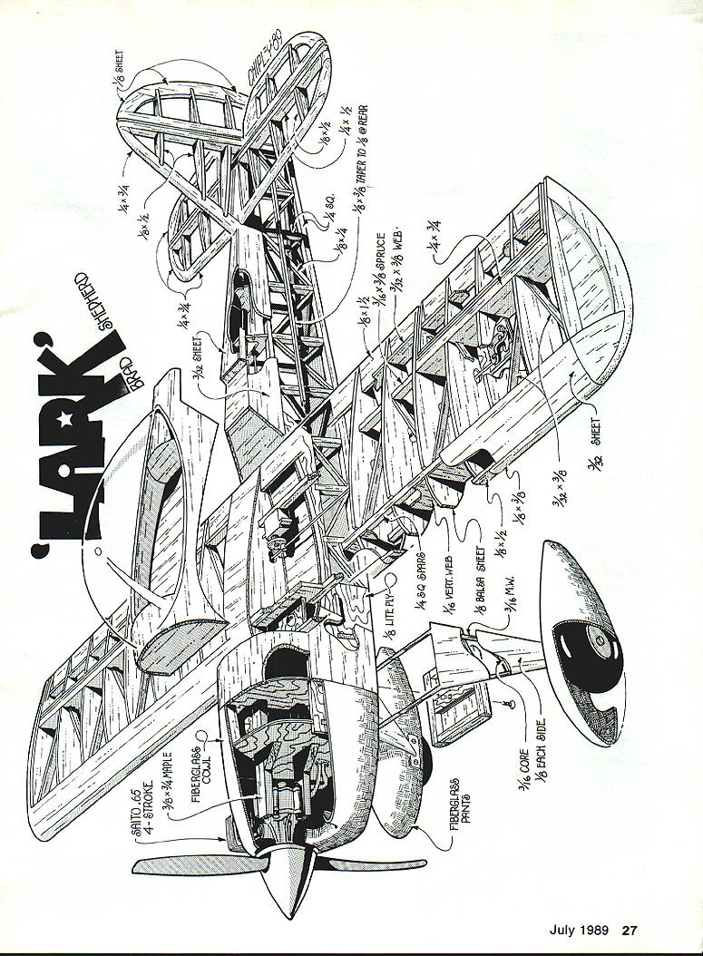
Construction
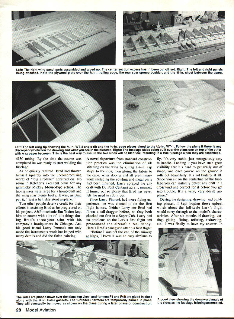
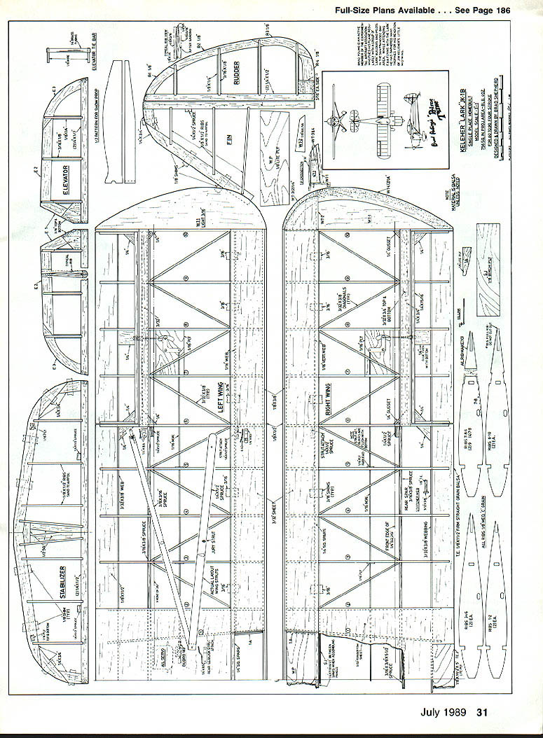
Wing
- Cut a set of master ribs from 1/32-in. ply to ensure accuracy. Mark each rib with its position.
- Pin a 1/4-in. sq. balsa spar on the jig line and place 3/16-in. shims under the front bottom spar. Pin the 1/4-in. sq. spar to the shims.
- Use a small 90° triangle of 1/32-in. ply to keep each rib vertical when installing on the spar. After all ribs are pinned, install the top 1/4-in. sq. spar and pin it.
- Install the 1/8 x 1/2-in. trailing edge into rib slots. When square and straight, use cyanoacrylate (CYA) glue on all joints—gap-filling CYA (e.g., Super Jet) is recommended.
- Install and glue the 3/32 x 3/16-in. aileron spar cap. Pin and glue the 1/8 x 3/8-in. leading edge. Slide the rear 3/16 x 3/8-in. spruce spar in place and glue.
- Cut and glue the 3/32 x 3/8-in. diagonals between ribs. Glue 1/16-in. vertical shear webbing to both sides of the spars. Install 1/4-in. gussets in corners.
- Sand a bevel into the 1/4-in. leading edge to conform with ribs and glue 3/32-in. leading edge sheeting in place. Turn the panel over, remove shims, pin down, and install remaining leading edge sheeting and aileron spar cap.
- Join panels on a flat surface (over a 70-in. straight line). Use aliphatic resin or epoxy to glue rear spar spruce joiner to spar stubs; clamp until dry. Glue Lite Ply trailing edge joiner, spar joiner, and ply joiners as specified in the plans.
- Glue 3/32-in. sheeting to the top center section aft of spars. Glue aileron cranks in place and install 1/8-in. music wire pushrods.
- Sheet the bottom center section. Note the offset position of the aileron servo—useful to counteract the weight of a side-mounted engine; unnecessary with a twin cylinder.
- Sand and round the leading edge to shape; install tips cut from 7/16-in. lightweight sheet balsa using the WT rib outlines (WT-1, WT-2, WT-3, WT-4). Use two WT-4 pieces (not WT-5) as per the plan. Glue 3/32-in. tip sheeting and sand to the rounded shape per the cross-section diagram.
- Build ailerons directly over the plans after installing ribs on the 1/8 x 1/2-in. trailing edge.
Tail Surfaces
- Cut outlines to shape. Glue 1/4 x 1/2-in. spars together to make a 1/2-in. sandwich—this reduces warping compared to using a solid 1/2-in. piece.
- Notch the spars and assemble surfaces over the plans. Sandwich construction of elevator and rudder yields a strong, lightweight structure that looks realistic when covered.
- Install hinges after assembly. Use .030-in. music wire for wire bracing on tail feathers; a 3/8-in. length of 3/32-in. brass tubing flattened on one end, drilled, and soldered to the wire makes the mounting tab. Use No. 2 screws through hardwood mounting plates and ply reinforcements on stab and fin. Sig No. 32 straight pins (secured with aliphatic resin) may simulate Dzus fasteners and PK screws.
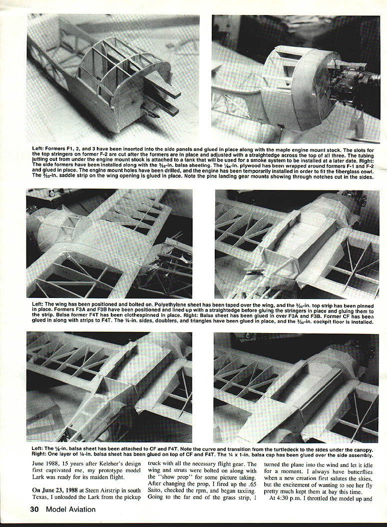
Fuselage
- Build using the one-side-on-top-of-the-other routine. Glue the Lite Ply doubler and 1/8-in. balsa sides together, insert waxed paper between sides, and build directly over the plan. Remember you have right and left side pieces.
- Contact cement was used on the prototype for ply/balsa pieces; CYA was applied around edges.
- Separate sides, pin them over the top view at former F-4 and the tail post. Trial fit former F-4 and F-4B; sand and trim as needed for snug fit.
- Epoxy F-6 in place, epoxy F-4B on top of F-4 and positioned against temporary angles. Use a 90° angle to get the tail post square, then glue sides together.
- Cut aft fuselage crosspieces in place (not over the plan), noting differences in top and bottom widths. Always follow the plans if photos and plans differ.
- Glue 1/8 x 1/4-in. diagonals per top view. Pin F-5 and F-6, trial fit stringers for straightness. Pin F-7 and trial fit 3/16 x 3/4-in. top longerons. Trim formers as necessary; glue stringers, formers, and longerons in place.
- Place F-1 in side slots and pull sides together with a rubber band. Slide F-3 in place and pin bottom sides to pull in and meet F-3 firmly. When satisfied with alignment, epoxy sides together at the top and glue sides together.
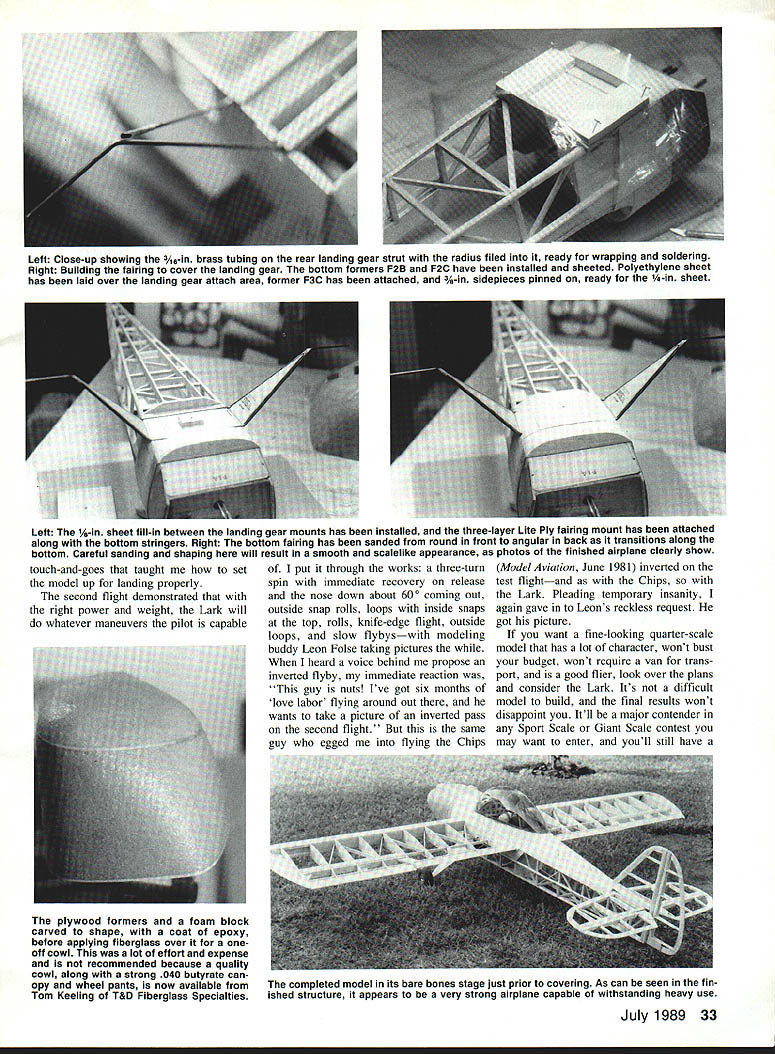
Landing Gear and Tailwheel
- Note the landing-gear mounting arrangement along a spreader bar with wing strut brass mounts behind the rear leg screwed to a 1/4 x 1/4-in. spruce strip, three-ply fairing, and hold-down block.
- File 3/16-in. brass tubing to enclose main landing gear wire, then wrap with soft wire as shown in the plans. Place gear in slots in pine blocks and hold with three 1/4-in. brass straps per leg or use commercial straps.
- Build the gear cover per photos and plans. Glue three-ply hold block to 1/8-in. sheet balsa fill-in. Drill through fairing and block, tap block for a 4-40 bolt, and screw fairing in place, sanding to fit F2-C and F3-C.
- Tailwheel was a homebrew assembly on the prototype; a commercial unit of appropriate size will serve just as well.
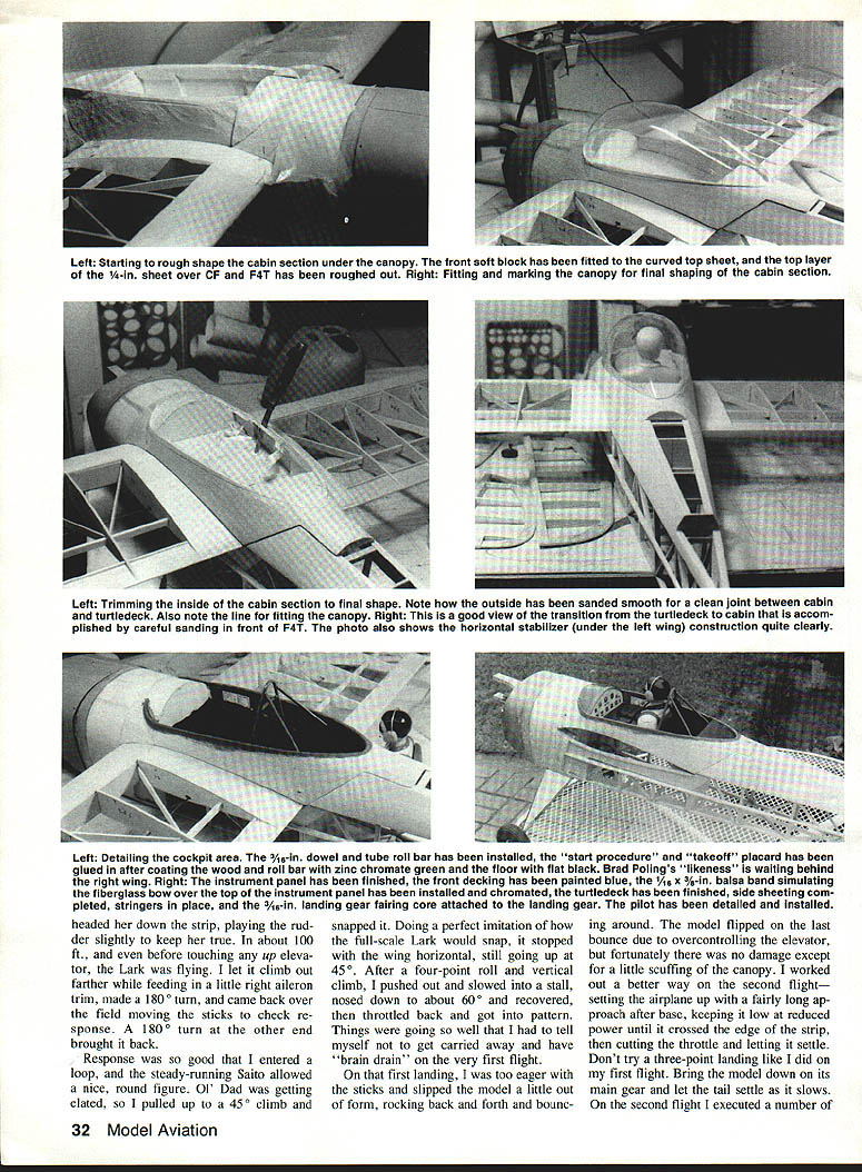
Cowling, Canopy and Cockpit
- Forming a one-off cowl from foam, fiberglass, and epoxy is time-consuming and costly. T&D Fiberglass Specialties offers ready-to-finish cowls, wheel pants, and canopies; the author recommends purchasing these—Tom Keeling’s sample cowl fit perfectly.
- The T&D canopy is formed from .040 material and required only slight trimming for a perfect fit. The author tried to mold a canopy 15 times before finally giving up and buying one.
- Radio equipment is stored in the antenna bay; the plans show the exact location.
- Build the cockpit floor and details: paint the floor flat black and the sides zinc chromate green. Construct a headrest rack with 3/8-in. aluminum tubing for the top radius and 3/16-in. doweling painted zinc chromate for the remainder. Paint the instrument panel almond.
- Mask and paint the front cockpit sheeting the same blue as the exterior finish (the prototype used Red Devil polyurethane in Empire Blue; Sig’s Blue Sky Bright is a close match).
- Simulate the fiberglass band on the full-size aircraft with a 1/8-in. thick by 3/4-in. wide balsa strip curved and glued across the top and painted chromate.
- Use a 3-in. scale pilot figure, block up to correct height, and dress as desired. Use shoelaces for parachute straps and shoulder harnesses. Glue placards and other details before gluing the canopy.
- Tint the canopy with black Rit dye in hot water; rinse with cold water and repeat until the desired light tint is achieved. Avoid tinting too dark. Glue the canopy with Testor’s cement (green tube) or similar.
Covering and Finishing
- It’s easier to cover tail surfaces before installing them on the fuselage. The prototype used Sig Koverall and nitrate dope with excellent results.
- After bolting on the wing, slip the stabilizer in place, ensuring it is square with the wing trailing edge and level. Confirm the stabilizer is true before gluing. Install elevators with Klett pinpoint hinges secured with aliphatic resin. Square the fin to the tail post using 90° angles. Make up or install the tailwheel assembly and secure with a ply plate epoxied to the fuselage bottom.
- The prototype received two coats of nitrate dope wherever Koverall met the structure (ribs, leading-edge sheeting, tips, trailing edges, fuselage stringers and sheeting, and turtledeck). Sand with 220-grit paper, then brush nitrate through the Koverall at contact points. Use a medium-heat iron to shrink the material.
- Brush five coats of thinned nitrate on the entire model. Apply a coat of thinned nitrate mixed with talcum powder (pure, without starch), sand smooth with 220 Tri-M-ite, then three more coats of nitrate sanded with 360-grit paper. Finish with polyurethane: a mist coat followed by a fairly wet coat.
- Graphic stripes: Coverite’s Graphic Stripes made the red stripes easy to apply; 1/4- and 1/8-in. sizes provided correct scale appearance and matched the full-size color.
- Lettering: "Prime Time" and Poling’s name were hand-painted with an 0-size sable brush using Sig Skybright Yellow and a red-mixed orange for the top half. Registration was applied with 3/4-in. Helvetica Presto Stick vinyl letters.
- Show prop: carved from a piece of 2 x 12-in. white pine shelving material, multiple coats of nitrate dope for high gloss, and painted white to match the model.
Flight Notes and Advice
- On the maiden flight the model climbed off cleanly and was highly responsive. Performance matched six months of detailed building—loops, rolls, outside snaps, knife-edge, outside loops, and spins with immediate recovery were all possible with proper power and weight.
- For landings: use a fairly long approach after base, keep low at reduced power until you cross the edge of the strip, then cut throttle and let the model settle onto the main gear. Avoid attempting a three-point landing until you’re confident.
- The aileron servo on the prototype is deliberately installed off-center to help counteract the weight of a side-mounted engine.
Recommendations and Final Thoughts
- If you want a fine-looking quarter-scale model that has character, won’t bust your budget, won’t require a van for transport, and is a good flier, consider the Lark. It’s an ideal project: conservative engineering, strong construction, good performance on low power, and easy handling.
- Buy a ready-made cowl and canopy if possible (T&D Fiberglass Specialties recommended). Use the plans as the authority when photos and plans differ.
- Enjoy the building and flying process—what started as a 15-year idea resulted in a rewarding model that flies off the workbench instead of the drawing board.
Design and author: Brad Shepherd, Victoria, TX
Transcribed from original scans by AI. Minor OCR errors may remain.

